Table of Contents
Advertisement
REPRODUCTION OF THIS MANUAL IN ANY FORM WITHOUT WRITTEN APPROVAL OF BAILEIGH INDUSTRIAL, INC.
IS PROHIBITED. Baileigh Industrial, Inc. does not assume and hereby disclaims any liability for any damage or loss
caused by an omission or error in this Operator's Manual, resulting from accident, negligence, or other occurrence.
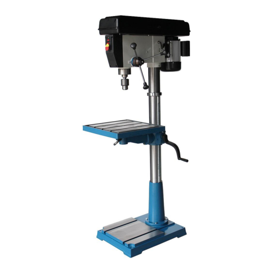
DRILL PRESS
MODEL: DP-2012F-HD-V3
Baileigh Industrial, Inc.
P.O. Box 531
Manitowoc, WI 54221-0531
Phone: 920.684.4990
Fax: 920.684.3944
sales@baileigh.com
© 2016 Baileigh Industrial, Inc.
OPERATOR'S
MANUAL
Rev. 04/2016
Advertisement
Table of Contents

Related Manuals for Baileigh Industrial DP-2012F-HD-V3


Summary of Contents for Baileigh Industrial DP-2012F-HD-V3
- Page 1 REPRODUCTION OF THIS MANUAL IN ANY FORM WITHOUT WRITTEN APPROVAL OF BAILEIGH INDUSTRIAL, INC. IS PROHIBITED. Baileigh Industrial, Inc. does not assume and hereby disclaims any liability for any damage or loss caused by an omission or error in this Operator’s Manual, resulting from accident, negligence, or other occurrence.
-
Page 2: Table Of Contents
Table of Contents THANK YOU & WARRANTY ..................1 INTRODUCTION ......................3 GENERAL NOTES ......................3 SAFETY INSTRUCTIONS ....................4 SAFETY PRECAUTIONS ....................6 Dear Valued Customer: ....................6 TECHNICAL SPECIFICATIONS ..................9 TECHNICAL SUPPORT ....................9 UNPACKING AND CHECKING CONTENTS ..............10 Cleaning ........................ -
Page 3: Thank You & Warranty
THANK YOU & WARRANTY Thank you for your purchase of a machine from Baileigh Industrial. We hope that you find it productive and useful to you for a long time to come. Inspection & Acceptance. Buyer shall inspect all Goods within ten (10) days after receipt thereof. Buyer’s payment shall constitute final acceptance of the Goods and shall act as a waiver of the Buyer’s rights to inspect or... - Page 4 • A 30% re-stocking fee applies to all returns. Baileigh Industrial makes every effort to ensure that our posted specifications, images, pricing and product availability are as correct and timely as possible. We apologize for any discrepancies that may occur. Baileigh Industrial reserves the right to make any and all changes deemed necessary in the course of business including but not limited to pricing, product specifications, quantities, and product availability.
-
Page 5: Introduction
After receiving your equipment remove the protective container. Do a complete visual inspection, and if damage is noted, photograph it for insurance claims and contact your carrier at once, requesting inspection. Also contact Baileigh Industrial and inform them of the unexpected occurrence. Temporarily suspend installation. -
Page 6: Safety Instructions
IMPORTANT PLEASE READ THIS OPERATORS MANUAL CAREFULLY It contains important safety information, instructions, and necessary operating procedures. The continual observance of these procedures will help increase your production and extend the life of the equipment. SAFETY INSTRUCTIONS LEARN TO RECOGNIZE SAFETY INFORMATION This is the safety alert symbol. - Page 7 SAVE THESE INSTRUCTIONS. Refer to them often and use them to instruct others. PROTECT EYES Wear safety glasses or suitable eye protection when working on or around machinery. PROTECT AGAINST NOISE Prolonged exposure to loud noise can cause impairment or loss of hearing. Wear suitable hearing protective devices such as ear muffs or earplugs to protect against objectionable or uncomfortable loud noises.
-
Page 8: Safety Precautions
SAFETY PRECAUTIONS Wood working can be dangerous if safe and proper operating procedures are not followed. As with all machinery, there are certain hazards involved with the operation of the product. Using the machine with respect and caution will considerably lessen the possibility of personal injury. However, if normal safety precautions are overlooked or ignored, personal injury to the operator may result. - Page 9 7. Drill Operation. Never start the drill press with the drill bit pressed against the piece part. Feed the drill bit slowly and evenly into the piece part. Position work to avoid drilling into the table. 8. Clearing Chips. Turn the machine OFF and clear chips and scrap pieces with a brush or with compressed air.
- Page 10 24. Inspect power and control cables periodically. Replace if damaged or bare wires are exposed. Bare wiring can kill! 25. Keep children away. Children must never be allowed in the work area. DO NOT let them handle machines, tools, or extension cords. Keep visitors a safe distance from the work area.
-
Page 11: Technical Specifications
TECHNICAL SPECIFICATIONS Type Belt Drive Motor 220V, 1PH, 60Hz, 1.5HP (1.1kw) Power Supply 220V, 60hz, 15A Spindle Speed 12 Position, 220 ~ 3200rpm 1/32" - 5/8” (0.8 - 16mm) JT3 Key Chuck Size 4.75” (120mm) Spindle Travel Spindle Taper MT4; MT4/JT3 20”... -
Page 12: Unpacking And Checking Contents
UNPACKING AND CHECKING CONTENTS Your Baileigh machine is shipped complete. Separate all parts from the packing material and check each item carefully. Make certain all items are accounted for before discarding any packing material. WARNING: SUFFOCATION HAZARD! Immediately discard any plastic bags and packing materials to eliminate choking and suffocation hazards to children and animals. -
Page 13: Cleaning
Cleaning WARNING: DO NOT USE gasoline or other petroleum products to clean the machine. They have low flash points and can explode or cause fire. CAUTION: When using cleaning solvents work in a well-ventilated area. Many cleaning solvents are toxic if inhaled. Your machine may be shipped with a rustproof waxy coating and/or grease on the exposed unpainted metal surfaces. -
Page 14: Transporting And Lifting
TRANSPORTING AND LIFTING IMPORTANT: Lifting and carrying operations should be carried out by skilled workers, such as a truck operator, crane operator, etc. If a crane is used to lift the machine, attach the lifting chain carefully, making sure the machine is well balanced. Follow these guidelines when lifting with truck or trolley: •... -
Page 15: Anchoring The Machine
• Remove scrap and waste materials regularly, and make sure the work area is free from obstructing objects. • It is important to maintain free area around the machine, which is required for the working place. If any long material is machined, it is necessary to have a sufficient room in front of the machine as well behind it in the places of material input and output. -
Page 16: Assembly And Set Up
ASSEMBLY AND SET UP WARNING: For your own safety, DO NOT connect the machine to the power source until the machine is completely assembled and you read and understand the entire instruction manual. Most of your Drill Press has been assembled at the factory, but some parts must be assembled or installed after delivery. - Page 18 11. Slide the column ring (19) onto the column with the inside bevel in the down position as shown. 12. Adjust the ring until the tip of the rack fits inside the bevel. The rack should now be captured in the bevel groove at the bottom and top. 13.
- Page 19 19. Rotate the headstock from side to side until the tip is equidistant from both the left and right sides. 20. Tighten the two setscrews located on each side of the headstock as shown to secure headstock to the column. Handles 21.
-
Page 20: Drill Chuck And Arbor
Drill Chuck and Arbor The drill chuck attaches to the drill spindle by means of a drill chuck arbor. Matched tapers on the arbor and chuck bore create solid assembly when properly joined. To assemble the drill chuck and mount it to the spindle, carefully follow the instructions below: IMPORTANT: The drill chuck, arbor and... - Page 21 Arbor Removal A drift key is included to aid in the drill chuck arbor removal. 1. Extend the spindle downward until the slot is exposed in the side of the quill. 2. Rotate the spindle until the inner slot is aligned with the outer as shown.
-
Page 22: Electrical
ELECTRICAL CAUTION: HAVE ELECTRICAL UTILITIES CONNECTED TO MACHINE BY A CERTIFIED ELECTRICIAN! Check if the available power supply is the same as listed on the machine nameplate. WARNING: Make sure the grounding wire (green) is properly connected to avoid electric shock. DO NOT switch the position of the green grounding wire if any electrical plug wires are switched during hookup. -
Page 23: Power Cord Connection
• Improper connection of the equipment-grounding conductor can result in risk of electric shock. The conductor with insulation having an outer surface that is green with or without yellow stripes is the equipment-grounding conductor. If repair or replacement of the electric cord or plug is necessary, do not connect the equipment-grounding conductor to a live terminal. -
Page 24: Electrical Schematic
ELECTRICAL SCHEMATIC... -
Page 25: Adjustments
ADJUSTMENTS WARNING: Make sure the power cord is disconnected and power is OFF before working on the machine. Always follow proper safety precautions when working on or around any machinery. Speed Changes The drill press has 12 speeds. There is a speed chart located on the inside of the upper belt guard. -
Page 26: Depth Stop
Depth Stop Your drill press comes with a depth stop adjustment for use when drilling. 1. Loosen the depth collar lock knob (A). 2. Secure the wood stock you will be drilling onto the drill press table. 3. With the desired bit installed, lower the spindle until the tip of the bit just touches the wood stock you will be drilling. - Page 27 Table Adjustment The table can be adjusted for height, rotation and angle. 1. Loosen the support bracket lock knob. Turn the table hand crank to lift or lower the table. 2. Always lock the support bracket in place before operating the machine. Adjust rotation: 1.
-
Page 28: Operation
OPERATION CAUTION: Always wear proper eye protection with side shields, safety footwear, and leather gloves to protect from burrs and sharp edges. When handling large heavy material make sure they are properly supported. Test Run Once assembly is complete and adjustments are done to your satisfaction, you are ready to test run the machine. -
Page 29: Lubrication And Maintenance
LUBRICATION AND MAINTENANCE WARNING: Make sure the electrical disconnect is OFF before working on the machine. Maintenance should be performed on a regular basis by qualified personnel. Always follow proper safety precautions when working on or around any machinery. Daily Maintenance •... -
Page 30: Greasing The Machine
Monthly Maintenance • Check that all screws and bolts are tight and secure. • Wipe built up grime from with a rag and a mild solvent. • Check for worn or damaged electrical cables. • Inspect regularly for tension and wear. Check pulleys to ensure that they are properly aligned. -
Page 31: Stand / Table Parts Diagram
STAND / TABLE PARTS DIAGRAM... -
Page 32: Headstock Parts Diagram
HEADSTOCK PARTS DIAGRAM... -
Page 33: Parts List
Parts List Item Part No. Description Size Qty. DP2012FHDV3-001 Base DP2012FHDV3-002 Hex Bolt M12x30 DP2012FHDV3-003 Rack DP2012FHDV3-004 Column DP2012FHDV3-005 Table Bracket DP2012FHDV3-006 Handle Arm DP2012FHDV3-006-1 Handle DP2012FHDV3-007 Set Screw M8x12 DP2012FHDV3-008 Shaft DP2012FHDV3-009 Hex. Nut DP2012FHDV3-010 Table Pin DP2012FHDV3-011 Flat Washer DP2012FHDV3-012 Hex Bolt M20x45... - Page 34 Item Part No. Description Size Qty. DP2012FHDV3-032 Ext Retaining Ring DP2012FHDV3-033 Shifter Bar DP2012FHDV3-034 Slide Bar Bolt DP2012FHDV3-035 Hex. Bolt M10X25 DP2012FHDV3-036 Flat Washer DP2012FHDV3-037 Hex Nut DP2012FHDV3-038 Hex. Nut DP2012FHDV3-039 Set Screw M10x12 DP2012FHDV3-041 Hex Nut DP2012FHDV3-042 Spring Cap w/Torsion Spring Part of item 42 Not sold separately No longer used...
- Page 35 Item Part No. Description Size Qty. DP2012FHDV3-060 5x5x25 DP2012FHDV3-061 Set Screw M6x10 DP2012FHDV3-062 V-Belt A-680 DP2012FHDV3-063 Center Shaft DP2012FHDV3-064 Thrust Ball Bearing 51107 DP2012FHDV3-065 Ball Bearing 6202-2RZ DP2012FHDV3-066 Hex Bo Ext Retaining Ring DP2012FHDV3-067 Center Pulley DP2012FHDV3-068 Flat Washer DP2012FHDV3-069 Phillip Head Screw M6x12 DP2012FHDV3-070...
- Page 36 Item Part No. Description Size Qty. DP2012FHDV3-094A Phillip Head Screw DP2012FHDV3-095 Light Socket DP2012FHDV3-096 Light DP2012FHDV3-097 Hex Wrench DP2012FHDV3-098 Hex Wrench DP2012FHDV3-099 Drift key DP2012FHDV3-100 Power Cord 100B DP2012FHDV3-100B Wire Gasket 100C DP2012FHDV3-100C Motor Cord DP2012FHDV3-104 Motor Fan Cover DP2012FHDV3-105 Speed Chart DP2012FHDV3-110 Strain Relief...
-
Page 37: Troubleshooting
TROUBLESHOOTING WARNING: Make sure the electrical disconnect is OFF before working on the machine. FAULT PROBABLE CAUSE REMEDY 1. Incorrect belt tension. 1. Adjust tension. 2. Dry Spindle. 2. Lubricate spindle. 3. Loose spindle pulley. 3. Checking tightness of retaining Noisy Operation nut on pulley, and tighten if necessary. - Page 38 NOTES...
- Page 39 NOTES...
- Page 40 BAILEIGH INDUSTRIAL HOLDINGS LLC 1625 D , WI 54220 UFEK RIVE ANITOWOC : 920. 684. 4990 F : 920. 684. 3944 HONE www.baileigh.com BAILEIGH INDUSTRIAL HOLDINGS LTD. U WIFT OINT WIFT ALLEY NDUSTRIAL STATE UGBY , CV21 1QH U IDLANDS...
Need help?
Do you have a question about the DP-2012F-HD-V3 and is the answer not in the manual?
Questions and answers