Table of Contents
Advertisement
Quick Links
Advertisement
Table of Contents

Related Manuals for Autel MAXICHARGER ACULTRA


Summary of Contents for Autel MAXICHARGER ACULTRA
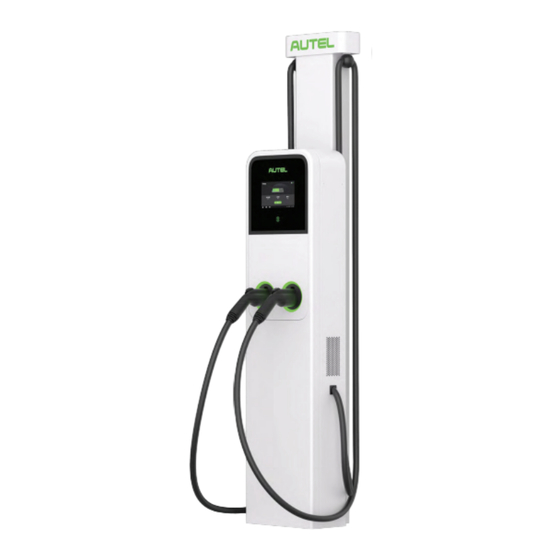
- Page 1 MAXICHARGER ACULTRA 19.2kW*2...
- Page 2 MAXICHARGER ACULTRA The Fastest AC Charger for Two Vehicles FAST AND EFFICIENT CREATE AN EXCEPTIONAL CHARGING EXPERIENCE At 19.2kW per port this charger leads the industry by fast charging 2 vehicles simultaneously, and generates 75 miles of range within 60 min Designed with ISO 15118 Plug & Charge, for a hassle-free charging experience BEST-VALUE DESIGN TAILORED FOR COMMERCIAL DEPLOYMENT Rugged design allows it to be wall-mounted or floor-mounted to support your application needs...
- Page 3 THE BIG VALUE BEHIND THE MAXICHARGER ACULTRA Weather Resistant 14.2 inch 11.3 inch...
-
Page 4: Technical Specifications
Dimensions (H×W×D) 625 × 320 × 170mm USER INTERFACE Status indication LED / APP / LCD (8 inch,1280*720 touch screen) User interface Autel Charge APP; Autel Charge Cloud Connectivity Bluetooth, Wi-Fi, Ethernet, 4G, RS485 Communication protocols OCPP 1.6J (Can be upgraded to OCPP 2.0.1 later) User authentication... - Page 5 User Manual MaxiCharger AC Ultra (UL)
- Page 6 All information, specifications and illustrations in this manual are based on the latest information available at the time of printing. Autel reserves the right to make changes at any time without notice. While information of this manual has been carefully checked for accuracy, no guarantee is given for the completeness and correctness of the contents, including but not limited to the product specifications, functions, and illustrations.
-
Page 7: Table Of Contents
CONTENTS 1 USING THIS MANUAL ............................1 ............................1 ONVENTIONS 1.1.1 Bold Text ............................. 1 1.1.2 Notes and Important Messages ......................1 1.1.3 Hyperlinks ............................1 1.1.4 Illustrations ............................1 1.1.5 Revision History ..........................1 2 SAFETY................................2 ............................2 AFETY ESSAGE .......................... - Page 8 4.3.4 Installing the Charging Station ......................33 4.3.5 Completing the Installation ......................37 + CMS ......................38 HARGING TATION EDESTAL 4.4.1 Checking the Box ..........................38 4.4.2 Installation Tools (Not Included) ...................... 40 4.4.3 Preparing a Foundation ........................41 4.4.4 Installing the Pedestal ........................42 4.4.5 Installing the Cable Management System (CMS)_Model A (Optional) ..........
-
Page 9: Using This Manual
Using This Manual This manual provides the installation and operation procedures of the MaxiCharger AC Ultra. Read through this manual and familiarize yourself with the instructions of the MaxiCharger prior to installation to ensure a successful installation and operation process. Conventions The following conventions are used: 1.1.1... -
Page 10: Safety
Safety Instructions The safety messages herein cover situations Autel is aware of. Autel cannot know, evaluate or advise you as to all of the possible hazards. You must be certain that any condition or service procedure encountered does not jeopardize your personal safety. - Page 11 ü Use 194 °F (90 °C) wire copper conductors only. ü Do not operate the equipment outside its operating temperature range of -40 to 131 °F (-40 to 55 °C). ü Incorrect installation and testing of the equipment could potentially damage the vehicle's battery, components, and/or the equipment itself.
-
Page 12: General Introduction
General Introduction The MaxiCharger AC Ultra has dual ports and single port available. Featured as "easy installation, convenient maintenance", the charger is designed as a commercial charger to charge electric vehicles (hereinafter referred to as EVs). The charger provides a safe, reliable, fast, and smart charging solution. This manual will instruct you on how to install and use this charger. -
Page 13: Product Overview
3.1 Product Overview 3.1.1 Front View Ambient Light Sensor 4 detects ambient light to adjust screen brightness 899 Capacitive LCD Touchscreen RFID Card Reader POS Payment Device (Optional) Status LED Connector Holster EV Charging Cable LED Description Description ü Solid Green: The MaxiCharger is in standby mode. ü... -
Page 14: Bottom-Up View
3.1.2 Bottom-Up View Conduit Knockout 4 remove before connecting AC input cable (s) Ethernet Cable Port 3.1.3 Back and Side Views Protruding Screw Mounting Hole Product Label 3.1.4 Inside View RJ45 Port SIM Card Tray... -
Page 15: Overview Of Pedestal (Optional)
3.1.5 Overview of Pedestal (Optional) Upper Front Cover Lower Front Cover Rubber Ring Strain Relief Mounting Location for Residual Current Breaker PE Busbar (for Pedestal) 3.1.6 Overview of Cable Management System (CMS) (Optional) There are two models of cable management system available, called Model A and Model B in this manual. Each model has two different heights: 107= (2.72 m) and 78= (1.97 m). -
Page 16: Electrical Design
3.2 Electrical Design Charging stations are considered continuous load devices (EVs draw maximum load for long durations); therefore, electrical branch circuits must be sized at 125% of the load for North American installations, in accordance with National Electric Code (NEC) requirements. (For other regions, refer to local code.) This means that for a maximum 80 A load at 208/240 V output to an electric vehicle, 100 A breakers are required. - Page 17 Single-port MaxiCharger Main Breaker PE Bus Breaker...
-
Page 18: Installation
Installation The MaxiCharger AC Ultra has four variations. Please follow the procedures accordingly depending on your order. Variation Overview of Installation Steps Installing the Charging Station Charging Station (Wall Mount) Connecting Wires See Chapter 4.1 for installation. Completing the Installation Installing the Pedestal Charging Station + Pedestal Installing the Charging Station... -
Page 19: Charging Station (Wall Mount)
4.1 Charging Station (Wall Mount) 4.1.1 Checking the Box Ensure the following items can be found in the package. Charging Socket Wrench Wall Dock Station (1 pc) (1 pc) (1 pc) Screwdriver T10 M6 x 50 *M5 x 10 Screw Screw (1 pc) (5 pcs) -
Page 20: Installation Tools (Not Included)
4.1.2 Installation Tools (Not Included) Prepare the following installation tools: ü Tape Measure ü Spirit Level ü Marker ü Drill ü Drill Bit, 0.31= (8 mm) ü Phillips Screwdriver ü Wire Stripper ü Crimping Tool ü Flathead Screwdriver ü Cable Lug (Recommended: EVN25-16 for L1&L2/N wire; RNB8-6S for PE wire) NOTE ü... -
Page 21: Installing The Charging Station
4.1.4 Installing the Charging Station Step 1 Place the drilling template against the wall, Drill the five holes at the marked locations minimum 18= (450 mm) above the ground, measuring 0.31= (8 mm) in diameter and and level it using a spirit level. 1.97= (50 mm) in depth in the wall. - Page 22 Step 2 1. Attach the wall dock to the mounting location by screwing three M6 x 50 screws into the upper holes. Tighten the three screws to 435 ft/lbs (537 Nm) using socket wrench provided. Step 3 1. Attach the charging station to the wall dock by inserting the two protruding screws on the back of the charging station into the...
- Page 23 2. Loosen the two M3 x 8 screws at the bottom of the charging station using the screwdriver T10 and remove the faceplate. Set them aside. 3. Unscrew the eight M3 x 8 screws using the screwdriver T10. Set the screws aside.
- Page 24 Mounting the Cable Hangers (Optional) Place the cable hangers against the wall, 30=339= (75031000 mm) above the ground and 12= (300 mm) from the charging station. Mark four holes on the wall. Remove the cable hangers temporarily. Drill the four holes at the marked location measuring 0.31= (8 mm) in diameter and...
-
Page 25: Completing The Installation
4.1.5 Completing the Installation 1. Ensure all the installation and wiring are secured and correct. Next, flip the maintenance cover downward. Reinsert the eight M3 x 8 screws and tighten them. 2. Reinstall the faceplate using the two M3 x 8 screws and tighten them accordingly. -
Page 26: Charging Station + Pedestal
4.2 Charging Station + Pedestal 4.2.1 Checking the Box Ensure the following items can be found in the package. Charging Wall Dock Screwdriver T10 Station (1 pc) (1 pc) (1 pc) Screwdriver Socket Wrench *M5 x 10 Screw (1 pc) (1 pc) NOTE ü... -
Page 27: Installation Tools (Not Included)
4.2.2 Installation Tools (Not Included) Prepare the following installation tools: ü Scoop Shovel (for digging a hole) ü Marker ü Drill ü Drill Bit, 0.7199 (18 mm) ü Open Spanner, 0.9499 (24 mm) ü Phillips Screwdriver ü Wire Stripper ü Crimping Tool ü... -
Page 28: Preparing A Foundation
4.2.3 Preparing a Foundation 1. Dig a hole according to the foundation dimensions. The recommended dimensions of the hole are 12= x 18= x 10= (300 x 460 x 250 mm) (H x W x D). IMPORTANT ü A flat and structurally sound concrete foundation is required for installation. -
Page 29: Installing The Pedestal
4.2.4 Installing the Pedestal Step 1 1. Loosen the upper two M5 x 20 security screws using the screwdriver T25 to remove the upper front cover. Set them aside. 2. Loosen the lower two M5 x 20 security screws using the screwdriver T25 to remove the lower front cover of the pedestal and... - Page 30 Step 2 1. Place and align the drilling template on the foundation. 2. Mark four mounting holes on the foundation. Remove the drilling template. 3. Drill four holes at the marked location measuring 0.7= (18 mm) in diameter and 6.3= (160 mm) in depth.
-
Page 31: Installing The Charging Station
4.2.5 Installing the Charging Station Step 1 Attach the charging station to the wall dock on the pedestal by inserting the two protruding screws on the back of the charging station into the two mounting holes and slide the charging station downwards. - Page 32 3. Reinstall the strain reliefs by screwing the four M4 x 15 screws and tighten the screws. Step 3 1. Loosen the two M3 x 8 screws using the 2. Remove the faceplate and set it aside. screwdriver T10 and set the screws aside.
- Page 33 3. Unscrew the eight M3 x 8 screws using the 4. Flip the maintenance cover upward. Next, screwdriver T10 and set the screws aside. insert the two M6 x 25 screws into the two holes and tighten them to 435 ft/lbs (537 Nm) to secure the charging station using the socket wrench.
-
Page 34: Completing The Installation
4.2.6 Completing the Installation Ensure all the installation and wiring are Reinstall the faceplate by reinserting the two secured and correct. Flip the maintenance M3 x 8 screws and tighten them. cover downward. Reinsert the eight M3 x 8 screws and tighten them. - Page 35 Reinstall the lower front cover of the pedestal 4. Reinstall the upper front cover of the pedestal by screwing the two M5 x 20 security screws and secure it with the two M5 x 20 security and tighten them. screws and tighten the screws. 5.
-
Page 36: Charging Station + Cms_M Odelb
4.3 Charging Station + CMS_Model B There are two kinds of cable management system in height: 107= (2.72 m) and 78= (1.97 m). For indoor installation, ensure that the space must be tall enough to accommodate the cable management system. 4.3.1 Checking the Box Charging... - Page 37 Cable Management System Kit Drilling Bracket Cover Template (1 pc) (2 pcs) (1 pc) Screw Bracket Base (M6 x 16) *Locating Pin (2 pcs) (11 pcs) Frame Hole Hole Plug Screw (M6 x 25) Cover (4 pcs) (2 pcs) (2 pcs) Wall Screw (M6 x 50) Anchor...
-
Page 38: Installation Tools (Not Included)
4.3.2 Installation Tools (Not Included) Prepare the following installation tools: ü Tape Measure ü Spirit Level ü Marker ü Drill ü Drill Bit, 0.31= (8 mm) ü Phillips Screwdriver ü Wire Stripper ü Crimping Tool ü Flathead Screwdriver ü Cable Lug (Recommended: EVN25-16 for L1&L2/N wire; RNB8-6S for PE wire) NOTE ü... -
Page 39: Installing The Cms
4.3.3 Installing the CMS Step 1 1. Place the drilling template against the wall and 3. Drill the eight holes at the marked locations level it using a spirit level. measuring 0.31= (8 mm) in diameter and 2.36= (60 mm) in depth on the wall. 2. - Page 40 Step 2 1. Attach the two bracket bases to the wall using the eight M6 x 50 screws. Use the socket wrench to tighten the screws to a torque of 435 ft/lbs (537 Nm). 2. Put the CMS in place and use the bracket covers to secure it to the bracket bases.
-
Page 41: Installing The Charging Station
4.3.4 Installing the Charging Station Step 1 1. Attach the wall dock to the upper bracket cover using the three M6 x 16 screws as shown in the diagram. 2. Tighten them to 435 ft/lbs (537 Nm) using the socket wrench. Step 2 1. - Page 42 Step 3 1. Attach the charging station to the wall dock by inserting the two protruding screws on the back of the charging station into the two upper mounting holes and slide the charging station downwards. 2. Loosen the screws of the cable clamps (two M3 x 10 screws each) using a Phillips screwdriver to detach the clamps.
- Page 43 4. Position the mark on the charging cable under the upper clamp. 5. Reinstall the lower clamp and tighten the screws. 6. Remove the two locating pins from the CMS. NOTE After the locating pins are removed, the CMS9s counterweights are relieved to move up and down.
- Page 44 8. Loosen the two M3 x 8 screws using the screwdriver T10 and remove the faceplate. Set them aside. 9. Unscrew the eight M3 x 8 screws using the screwdriver T10. Set the screws aside. 10. Flip maintenance cover upward. Next, insert the two M6 x 50 screws and tighten them to 43 5 ft/lbs (537 Nm) using the socket wrench to secure the charging...
-
Page 45: Completing The Installation
4.3.5 Completing the Installation 1. Ensure all the installation and wiring are secured and correct. Next, flip the maintenance cover downward. Reinsert the eight M3 x 8 screws and tighten them. 2. Reinstall the faceplate using the two M3 x 8 screws and tighten them accordingly. -
Page 46: Charging Station + Pedestal + Cms
4.4 Charging Station + Pedestal + CMS There are two kinds of cable management system in height: 107= (2.72 m) and 78= (1.97 m). For indoor installation, ensure that the space must be tall enough to accommodate the cable management system. 4.4.1 Checking the Box Ensure the following items can be found in the package. - Page 47 Cable Management System Kit CMS_Model A (1 pc) CMS_Model B Drilling Bracket Cover Template (1 pc) (2 pcs) (1 pc) Screw Bracket Base (M6 x 16) *Locating Pin (2 pcs) (11 pcs) Frame Hole Hole Plug Screw (M6 x 25) Cover (4 pcs) (2 pcs)
-
Page 48: Installation Tools (Not Included)
4.4.2 Installation Tools (Not Included) Prepare the following installation tools: ü Scoop Shovel (for digging a hole) ü Marker ü Drill ü Drill Bit, 0.7199 (18 mm) ü Open Spanner, 0.9499 (24 mm) ü Phillips Screwdriver ü Wire Stripper ü Crimping Tool ü... -
Page 49: Preparing A Foundation
4.4.3 Preparing a Foundation 1. Dig a hole according to the foundation dimensions. The recommended dimensions of the hole are 18= x 18= x 10= (460 x 460 x 250 mm) (W x D x H). IMPORTANT ü A flat and structurally sound concrete foundation is required for installation. -
Page 50: Installing The Pedestal
4.4.4 Installing the Pedestal Step 1 1. Loosen the upper two M5 x 20 security screws using the screwdriver T25 to remove the upper front cover. Set them aside. 2. Loosen the lower two M5 x 20 security screws using the screwdriver T25 to remove the lower front cover of the pedestal and... - Page 51 Step 2 1. Place and align the drilling template on the foundation. 2. Mark four mounting holes on the foundation. Remove the drilling template. 3. Drill the four holes at the marked location measuring 0.7= (18 mm) in diameter and 6.3= (160 mm) in depth.
-
Page 52: Installing The Cable Management System (Cms)_Model A (Optional)
4.4.5 Installing the Cable Management System (CMS)_Model A (Optional) Step 1 1. Place the CMS on the back of the pedestal, aligning the slot (A) on the bottom of the CMS to the knob (B) on the bottom of the pedestal. - Page 53 2. Locate the recommended hanging point by either of the following two methods: Distance between Charging Cable9s Length Hanging Point and Connector (H) a) If needed, mark the hanging point (metering from the connector) on the 25.169 (7.67 m) 12.479 (3.8 m) charging cable according to the table.
-
Page 54: Installing The Cable Management System (Cms)_Model B (Optional)
4.4.6 Installing the Cable Management System (CMS)_Model B (Optional) 1. Place the CMS on the back of the pedestal, aligning the slot (A) on the bottom of the CMS to the knob (B) on the bottom of the pedestal. 2. Attach the two bracket covers to the CMS using the eight M6 x 16 screws. - Page 55 3. Insert the two locating pins from both sides. 4. Remove the two M6 x 30 screws in the front using a Phillips screwdriver.
-
Page 56: Installing The Charging Station
4.4.7 Installing the Charging Station Step 1 Attach the charging station to the wall dock on the pedestal by inserting the two protruding screws on the back of the charging station into the two mounting holes and slide the charging station downwards. Step 2 1. - Page 57 3. Reinstall the strain reliefs by screwing and tightening the four M4 x 15 screws. 4. Hang the charging cable to the cable clamp. See Step 2 (1-4) in the Section 4.4.5 for details. Cable Management System_Model B only. 5. Remove the locating pins from the CMS. Cable Management System_Model B only.
- Page 58 3. Unscrew the eight M3 x 8 screws using 4. Flip the maintenance cover upward. Next, insert the the screwdriver T10 and set the screws two M6 x 25 screws into the two holes and tighten aside. them to 435 ft/lbs (537 Nm) to secure the charging station using the socket wrench.
-
Page 59: Completing The Installation
4.4.8 Completing the Installation 1. Ensure all the installation and wiring are secured Reinstall the faceplate by reinserting the two and correct. Flip the maintenance cover M3 x 8 screws and tighten them. downward. Reinsert the eight M3 x 8 screws and tighten them. - Page 60 Reinstall the lower front cover of the pedestal 4. Reinstall the upper front cover of the pedestal by screwing and tightening the two M5 x 20 and secure it with the two M5 x 20 security security screws. screws and tighten the screws. Plug the charging connectors into the holsters.
-
Page 61: Ac Input Wiring
4.5 AC Input Wiring 4.5.1 Cable Specifications Wire Size Cable Lug 4 AWG EVN25-16 L2/N 4 AWG EVN25-16 4 AWG RNB8-6S 4.5.2 Installing Conduit NOTE This section is applicable for Charging Station (Wall Mount) and Charging Station + CMS_Model B. Before connecting the AC input cable, remove the 1.69-inch (43 mm) conduit knockout (A) and install the appropriate conduit depending on single input or dual inputs. -
Page 62: Connecting The Wires
4.5.3 Connecting the Wires 1. Strip the wires to 0.63= (16 mm). Single-port MaxiCharger 2. Use a crimping tool to attach cable lugs (not provided) to the exposed core wires. 3. Insert the AC input cable into the inlet hole. 4. -
Page 63: Adjusting The Rated Current
Install the Power Sharing Kit (For the Dual-port MaxiCharger Only) For single input application to the dual-port MaxiCharger, before connecting L1, L2/N, and PE wires, install the power sharing kit: put the four spacers (C) into the four holes respectively and cover them with the two double tee nuts (B). -
Page 64: Connecting To The Internet
4.6 Connecting to the Internet The MaxiCharger AC Ultra can access the Internet via Ethernet Cable, Wi-Fi or cellular network. The installation process vary between Ethernet cable and cellular network connections. No mechanical or electrical installation is needed for Wi-Fi connection. Select the optimal method to connect the Internet and follow the steps below accordingly. -
Page 65: Via Cellular Network
6. Reconfirm that the input voltage is within the range of 161 3 276 VAC. If it exceeds the range, connect the correct power; if it is correct, proceed with next step. 7. Contact Autel technical support to turn on the upstream breaker and check the screen display. ü If the screen display doesn9t work properly, please contact Autel technical support. -
Page 66: Local Service Portal Operations
Local Service Portal Operations 5.1 Setting the OCPP Parameters NOTE The settings should be performed by an installation engineer. After startup, set the settings on screen. 1. Select the language. 2. Select the network. 3. Select the time zone... - Page 67 4. Select the input cable. 5. Set the input cable current. NOTE ü For the dual-port MaxiCharger, <Cable 1= means the cable that supplies the power to the left port facing the charger. ü <Cable 2= input current will be required to be set for dual inputs.
- Page 68 Detailed device settings can be set in Device Maintenance. Follow the instructions below to set the OCPP parameters. 1. Tap on the icon $ to open the Cost Details page. 2. Double-click the upper-left corner of the screen. 3. Tap Device Maintenance. Enter the password to continue.
- Page 69 4. Then the device maintenance screen will appear. Tap Set Parameters to set the OCPP parameters. 5. Set following parameters according to the actual conditions. Tap the parameter in the Parameter Value column to change the setting. ü <Output power sharing= is required to only dual-port MaxiCharger with single input.
-
Page 70: Configuring The Cloud Platform
5.2 Configuring the Cloud Platform The Autel Charge Cloud, a one-stop charging management solution, is intended to address the needs of many use-cases including commercial, residential, governmental, car dealers, and fleets. Contact Autel technical support for subscription and learn more details on Autel Charge Cloud manual. -
Page 71: Maintenance
Maintenance WARNING ü Disconnect the power supply to the MaxiCharger during the entire maintenance procedure. ü Make sure that unauthorized personnel are kept at a safe distance during maintenance. ü Wear proper personal protective equipment, such as protective clothing, safety gloves, safety shoes, and safety glasses. -
Page 72: Special Inspections
ü System self-check for abnormality daily. ü If any abnormal operation is found, contact your local dealer or Autel technical support promptly. ü Autel service engineers can check logs, update configurations and programs, and provide remote maintenance services, such as remote management, diagnosis, configuration, and upgrades. -
Page 73: Troubleshooting
Troubleshooting Item Problems Solutions Do not insert the connector into your EV charging The charging session does not start as port before setting up a charging schedule for the scheduled. first time. Insert the EV charging cable after the schedule is set up. Use the multimeter to check whether the voltage on the power input is too high. -
Page 74: Specifications
Specifications 8.1 General Specifications Description Item Single Port Dual Ports AC Power Output Rating 19.2 kW 19.2 kW x 2 208/240 V AC 60 Hz single phase @ 16 A, 24 A, 32 A, 40 A, 48 A, 50 A, AC Power Input Rating 64 A, 72 A, 80 A 20 A, 30 A, 40 A, 50 A, 60 A, 70 A, 80 A, 90 A,100 A... - Page 75 Description Item Single Port Dual Ports ü Overcurrent ü Overvoltage Protection ü Undervoltage ü Integrated surge protection ü 4G ü Wi-Fi Connectivity ü Ethernet ü RS485 ü ISO 15693 ü ISO 14443 Card Reader ü NFC ü Credit Card (Optional) ü...
- Page 76 Description Item Single Port Dual Ports Operating Altitude 6561.7 ft. (2000 m) ü Charging Station: 25= x 13= x 7= (625 mm x 320 mm x 170 mm) ü Pedestal: 5799 x 1499 x 899 (1440 mm x 360 mm x 197 mm) ü...
-
Page 77: Product Dimensions
8.2 Product Dimensions Charging Station Front View Bottom View Pedestal Front View Side View... - Page 78 Cable Management System Front View Front View Side View...
-
Page 79: Compliance
Compliance FCC regulatory conformanceÿ This device complies with Part 15 of the FCC Rules. Operation is subject to the following two conditions: (1) This device may not cause harmful interference. (2) This device must accept any interference received, including interference that may cause undesired operation. - Page 80 Economic Development Canada's licence-exempt RSS(s). Operation is subject to the following two conditions: (1) This device may not cause interference. (2) This device must accept any interference, including interference that may cause undesired operation of the device. Cet appareil est conforme à la norme CAN ICES-3 (B)/NMB-3 (B). Cet appareil contient des émetteurs / récepteurs exempt (s) de licence qui sont conformes aux RSS exemptes de licence d'Innovation, Sciences et Développement économique Canada.
-
Page 81: Appendix
Appendix 10.1 Fault Code List The table below contains the fault codes on the Autel Charge Cloud and their descriptions on the charger9s display. Fault Codes Descriptions Mains overvoltage Mains undervoltage Mains over-frequency Mains under-frequency Phase loss Line/Neutral reverse connection... - Page 82 Fault Codes Descriptions 20000000 Temperature sensor abnormal 40000000 Power System abnormal...
- Page 83 www.autelenergy.com...
Need help?
Do you have a question about the MAXICHARGER ACULTRA and is the answer not in the manual?
Questions and answers