Table of Contents
Advertisement
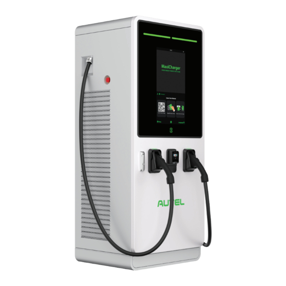
MAXICHARGER
DC FAST 60KW-240KW
SPECIFICATIONS
•
FLEXIBLE POWER MODULE DESIGN
•
MULTIPLE CABLE & CHARGING
CONNECTOR OPTIONS
• 27-INCH TOUCHSCREEN DISPLAY
1.844.765.0150
I
WWW.AUTELENERGY.COM
™
•
SMART CLOUD PORTAL WITH
REMOTE DIAGNOSTICS
• DYNAMIC LOAD BALANCING
• ISO 15118 PLUG & CHARGE
I
AUTELENERGY@AUTEL.COM
WITH 20KW
INCREMENTS
Advertisement
Table of Contents


Need help?
Do you have a question about the MAXICHARGER DCFC 60kW and is the answer not in the manual?
Questions and answers