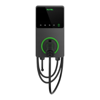
Autel MaxiCharger Quick Reference Manual
Ac wallbox pedestal
Hide thumbs
Also See for MaxiCharger:
- Installation manual ,
- Installation and operation manual (78 pages) ,
- Manual (54 pages)
Table of Contents
Advertisement
Quick Links
Web: www.autelenergy.com
Thank you for purchasing this Autel equipment. Our equipment is manufactured to a high standard and — when used
according to these instructions and properly maintained — will provide years of trouble-free performance.
IMPORTANT:
1. Before operating or maintaining this equipment, please read these instructions carefully, paying extra attention to
the safety warnings and precautions. Failure to install or use this equipment properly may cause damage and/or
personal injury and will void the product warranty.
2. This guide is a supplement to the MaxiCharger AC Wallbox Installation Manual, and the installation instructions
on location selection and wiring, etc. must be adhered to.
3. This guide applies to both the single pedestal and the back-to-back pedestal installation.
WARNING
• This equipment should only be installed by a licensed electrician and in accordance with all local codes and ordinances.
• Do not install or use this equipment near flammable, explosive, harsh, or combustible materials, chemicals or vapors.
• Handle the equipment with care during transportation to prevent damage to it or any components. Do not subject it to
strong force or impact or pull, twist, tangle, drag or step on the device.
• The respective national regulations must be observed with regard to the installation of the pedestals.
• When mounting the pedestals in parking spaces or parking garages, appropriate anti-collision protection must be provided
by the installer.
Preparing for Installation
Foundation Requirements
• A horizontal, level, and sound foundation is required for
installation. To ensure safe and permanent anchoring, the
concrete strength level should be above C30.
• The base must permit the running off of any water that
has entered the base.
• The diameter of the embedded cable should not exceed
80 mm. All cables must be laid precisely in the center of
the concrete foundation from the base and must have an
excess length of approx. 1.5 m for the remaining installa-
tion activities.
• Do not mount the pedestal on asphalt.
NOTE: If you want to construct a concrete foundation,
we recommend its size to be 364 x 300 x 100 mm (L x W x D).
Alternatively, you can construct the foundation referring to the
size of the pedestal base (see diagram below). And the
foundation should use the uncracked concrete.
Quick Reference Guide
Drilling Holes
1. Mark the four holes on the concrete foundation using
the base plate of the pedestal. Make sure that the
connection cable is located precisely underneath the
opening in the base plate.
2. Drill the four mounting holes with 12 mm in diameter
and minimum 60 mm in depth.
Installing the Pedestal
There are two ways to insert the cable:
• Via the bottom entry opening
• Via the rear entry opening
12
(Unit: mm)
MaxiCharger AC Wallbox Pedestal
Advertisement
Table of Contents

Summary of Contents for Autel MaxiCharger
- Page 1 MaxiCharger AC Wallbox Pedestal Web: www.autelenergy.com Thank you for purchasing this Autel equipment. Our equipment is manufactured to a high standard and — when used according to these instructions and properly maintained — will provide years of trouble-free performance. IMPORTANT: 1.
- Page 2 Product Specifications 153.8 1400 1400 (Unit: mm) Weight: 7.3 kg Material: Stainless Steel 304 Front Side Bottom Entry Installation Lower cable exit 1. Put down the pedestal. Thread the cable through the bottom of the pedestal and out the lower cable exit. Cable entrance 2.
- Page 3 Rear Entry Installation 1. Remove the blank upper cover plate (E) from the pedestal by unscrewing the four M3 x 6 screws (F). Upper cable exit 2. Thread the cable through the bottom of the pedestal and out the upper cable exit. Cable entrance 3.
- Page 4 Installing the Cable Holder Align the cable holder (K) with the installation holes (L). Insert two M4 x 8 screws into the holes. Tighten the screws to secure the cable holder. Installing the Wall Dock 1. Align the wall dock with the two mounting holes (M). 2.


Need help?
Do you have a question about the MaxiCharger and is the answer not in the manual?
Questions and answers