Autel MaxiCharger Installation And Operation Manual
Ac wallbox
Hide thumbs
Also See for MaxiCharger:
- Installation manual ,
- Manual (54 pages) ,
- Installation and operation manual (20 pages)
Table of Contents
Advertisement
Advertisement
Table of Contents

Related Manuals for Autel MaxiCharger


Summary of Contents for Autel MaxiCharger
- Page 1 MaxiCharger AC Wallbox Installation and Operation Manual Version 3.0 Europe...
- Page 2 All information, specifications and illustrations in this manual are based on the latest information available at the time of printing. Autel reserves the right to make changes at any time without notice. While information of this manual has been carefully...
- Page 3 For Services and Support: Web: www.autelenergy.eu Tel: +49 (0) 89 540299608 (Europe) Email: evsupport.eu@autel.com Address: Landsberger Str. 408/4. OG 81241 Munich, Germany For technical assistance in all other markets, please contact your local selling agent.
-
Page 5: Table Of Contents
CONTENTS Using This Manual 1.1 Conventions 1.2 Revision History Safety 2.1 Safety Warnings 2.2 Disposal Instructions General Introduction 3.1 Product Overview 3.2 Options 3.3 Display Description 3.4 Wiring Diagram for MCB, RCD, and Emergency Stop 3.5 Product Model 3.6 In the Box 3.7 Recommended Tools Installation 4.1 Unpacking... - Page 6 4.6 Finish Installation 4.7 Protective Device Operation 5.1 Energizing the Charging Station 5.2 Start Charging 5.3 Stop Charging Troubleshooting and Service 6.1 Troubleshooting Table 6.2 Service Specifications 7.1 Cable Specifications 7.2 Supplementary Specifications 7.3 Manufacturer and Models 7.4 Product Dimensions Compliance Appendix 9.1 Fault Code List...
-
Page 7: Using This Manual
Using This Manual This manual describes the installation and use of the MaxiCharger AC Wallbox. Prior to installation, read through this manual to be familiarized with the instructions of this MaxiCharger to ensure a successful installation and smooth operations. Conventions... -
Page 8: Revision History
IMPORTANT IMPORTANT indicates a situation which, if not avoided, may result in damage to the test equipment or vehicle. ILLUSTRATION Illustrations used in this manual are only examples; the actual product(s) or screens may vary. Revision History Version Date Descriptions 2022.05.10 Initial version Merged user manual and... -
Page 9: Safety
Safety Safety messages are provided to help prevent personal injury and equipment damage. All safety messages are introduced by a single word indicating the hazard level. DANGER Indicates an imminently hazardous situation with a high risk level which, if the danger is not avoided, will cause death or serious injury. -
Page 10: Safety Warnings
Safety Warnings The safety messages herein cover situations Autel is aware of. Autel cannot know, evaluate or advise you as to all of the possible hazards. You must be certain that any condition or service procedure encountered does not jeopardize your personal safety. - Page 11 Do not put the charging handle into any liquid. Do not install or open the MaxiCharger in wet environment (such as rain or heavy fog). Ensure that the charging cable is positioned so that it will not be stepped on, tripped over, driven over or otherwise subjected to excessive force or damage.
-
Page 12: Disposal Instructions
Do not leave objects inside the charging port. Keep and use (electro) magnetic devices at a safe distance from the MaxiCharger. Disposal Instructions Handling waste incorrectly can have a negative effect on the environment and human health due to potential hazardous substances. -
Page 13: General Introduction
This manual will instruct you how to install and use this charging station. Intended Use This MaxiCharger is intended for the AC charging of EVs. It is intended for both indoor and outdoor use. Residential ... - Page 14 DANGER If you use the charger in any way other than described in this manual or other related documents, possible death, injury and damage to property can occur. Use the charger only as intended. NOTE This manual is for cable, socket, and shutter models.
-
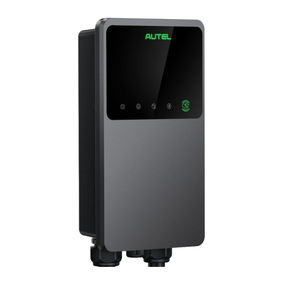
Page 15: Product Overview
Product Overview LED Indicators (from left to right): Power LED Internet Connection LED Charging LED Bluetooth Connection LED RFID Reader AC Input Cable... - Page 16 RJ45 Ethernet Port Mounting Screws Rear Entry Signal Conduit Plug Rear Entry Power Conduit Plug Product Label...
- Page 17 LED Description Description Solid Green: The charging station is on. Off: The charging station is off. Flashing Yellow: Data is being transmitted Power LED and/or firmware is upgrading. Solid Yellow: Firmware upgrade has failed. Solid Blue: Data transmission has failed; will turn solid green in five seconds.
- Page 18 Solid Blue: An EV is connected. Flashing Blue: A schedule is active. Flashing Cyan: The charging station is reserved. Flashing Green: An EV is charging. Solid Yellow: A recoverable error has occurred Charging LED or it is temporarily disabled by the server. Solid Green: A charge session has ended.
-
Page 19: Options
Options Display Ambient Light Sensor —detects ambient brightness Display Energy Pulse Output (Infrared Ray) - Page 20 Cable Model With Holster Without Holster...
- Page 21 EV Charge Cable NOTE Drape the EV charge cable over the top of the MaxiCharger and dock the connector in its holster when not in use. See the figure on the left. The maximum length of the EV charge cable is...
- Page 22 Socket/Shutter Model Socket/Shutter, Type 2 SIM Card Socket SIM Card Socket (Available on charging stations with 4G function.)
-
Page 23: Display Description
Display Description IMPORTANT This section is only applicable to charging stations with a display. Function Buttons Button Description Tap to view the charging cost. Cost Details Tap to choose your language for the Language charging station. Tap to stop a charge session. Stop Tap to confirm the information on the screen. - Page 24 3.3.1 Boot Screen The display shows the Boot screen while the charging station starting up.
- Page 25 3.3.2 Standby/Authorization Screen Top — displays total delivered energy, time, signal strength, and Bluetooth connection Middle — provides two authorization methods: QR code or RFID card Bottom — tap to view the charging costs and adjust the language The display shows the Standby/Authorization screen when the charger is in idle status, indicating that the charging station is ready for use.
- Page 26 3.3.3 Preparing to Charge Screen...
- Page 27 3.3.4 Charging Screen The Charging screen appears during the charge session. Top screen Main Charging screen — shows the real-time charging progress and other charging information including energy, duration, current cost, power, voltage, as well as current per phase. Stop button — tap to stop the charge session...
- Page 28 3.3.5 Transaction Details Screen When the charge session ends, the Transaction Details screen will appear. Tap the OK button to confirm your transaction details.
- Page 29 3.3.6 Device Information Screen The actual Device Information screen may differ. 3.3.7 Error Information Screen The display shows different error messages depending on the error type. The charging station fails to start a charge session:...
- Page 30 Tap the OK button to confirm the message. An error has occurred with the charging station. Contact Autel support.
-
Page 31: Wiring Diagram For Mcb, Rcd, And Emergency Stop
Wiring Diagram for MCB, RCD, and Emergency Stop For 7.4 kW model: For 11/22 kW Model:... -
Page 32: Product Model
Product Model The MaxiCharger AC Wallbox model is a code that consists of seven parts: Maxi U W - XX - YY - L - M - ZZ Code Description Value Meaning of Value Part EU AC EU AC series... - Page 33 Vehicle connector with 5- meter cable Vehicle connector with 7.5- meter cable Socket-outlet (Not for 11kW models) Shutter-outlet (Not for 11kW models) 4G function embedded Wireless function Blank Standard type LCD panel function MID function Dark grey White Rose gold Color Silver Black...
-
Page 34: In The Box
In the Box Charging Wall Dock Station 1 PC 1 PC Screw Screw (M6 x 50) (M5 x 12) 2 PCS 1 PC Wall Plug Charge Card (8 mm) 2 PCS 2 PCS Cable Sealing Cable Sealing Ring (M25) Ring (M16) 1 PC 1 PC Screw... -
Page 35: Recommended Tools
Recommended Tools NOTE The tools mentioned below are not included in the package. Ensure they are readily available prior to installation. Spirit Level Crimping Tool Screwdriver Pencil (PH2) Wire Stripper Power Drill Drill Bit Tape Measure (8 mm) Multimeter... -
Page 37: Installation
Installation IMPORTANT All required permits have been acquired in accordance with the local regulations. The AC input cable is available. There is no voltage on the AC input cable throughout the installation procedure. Unpacking Open the box. Remove the charging station from the box. -
Page 38: Preparation
Preparation Install the charging station on a flat and vertical surface capable of supporting its weight (e.g. a finished brick or concrete wall, a pedestal, etc.). The maximum weight of a charging station is about 6 kg (13 lbs.). ... -
Page 39: Mechanical Installation
Mechanical Installation STEP 1 Place the wall dock against the wall and level it using a spirit level. Mark the two lower mounting holes (A) with a pencil and drill two 8 mm holes. Insert the two 8 mm wall plugs (B) into the holes. - Page 40 STEP 3 Attach the charging station to the wall dock by inserting the two protruding screws (E) on the back of the charging station into the two upper mounting holes (F). Slide the charging station downwards to engage the screws. STEP 4 Insert and tighten the included M5 x 12 screw (G) into the hole at...
-
Page 41: Power Supply Wiring
Power Supply Wiring IMPORTANT Consult the local electrical codes for the correct wire size, based on the environment, the conductor type, and the rating of the charging station. Ensure that all the screws are tightened to the correct torque after the wiring is completed, and that there are no loosen screws at the terminal blocks. - Page 42 STEP 1 Remove the two screws (I) at the bottom of the charging station with the T10 Torx screwdriver. Then remove the faceplate from the middle of the clasp (H). Set them aside. Unscrew the five screws (J) to remove the maintenance cover (K).
- Page 43 STEP 2 Single-phase Wiring: Strip the wires to 12 mm. Loosen the lower-left cable gland, insert the AC input cable through the inlet hole, and pre-fix the cable gland. Loosen the screws at the terminal block. Insert the cable connector into the terminal block. Connect the following wires as specified: ...
- Page 44 Three-phase Wiring: Strip the wires to 12 mm. Loosen the lower-left cable gland, insert the AC input cable through the inlet hole, and pre-fix the cable gland. Loosen the screws at the terminal block. Insert the cable connector into the terminal block. Connect the following wires as specified: ...
-
Page 45: Internet Connection
Internet Connection The charging station can be connected to the Internet by Ethernet connection, Wi-Fi or a SIM card. Via the Ethernet Cable: STEP 1 Connect the waterproof Ethernet cable gland to the Ethernet cable: Put the Ethernet cable with RJ45 plug (a) through the nut (b) and the waterproof cap (d) (leave some space... - Page 46 STEP 2 Put the RJ45 plug of the Ethernet cable into the RJ45 port (L) at the bottom of the charging station. Via the SIM Card: Remove the M3 x 10 screw using the T10 screwdriver to open the SIM card cover. Use an appropriate tool to press the tiny button next to the SIM card tray (M) and...
-
Page 47: Finish Installation
Finish Installation 4.6.1 Reinstall the Covers Reinstall the inner cover by tightening the five screws to the right torque. Reinstall the maintenance cover by tightening the two screws at the bottom of the charging station. 4.6.2 Distribution Box Wiring Procedures above complete the power supply wiring to the charging station. - Page 48 Distribution Box Wiring for Single-phase: Distribution Box Wiring for Three-phase: Terminal Block RS485 Communications Cables with Electrical Tape...
-
Page 49: Protective Device
Protective Device Devices Specifications Options: Dedicated upstream RCD (Type A minimum) + MCB protection device(s) RCBO (Type A minimum) Breaker rating: Upstream overcurrent protection breaker, 40 A for a 32 A rated charging such as RCBO or MCB station (The breaker serves as 20 A for a 16 A rated charging the main disconnect station... - Page 50 (for the electrician to decide). The MaxiCharger AC Wallbox has the internal 30 mA AC and 6 mA DC residual current detection. In some countries, local standards may require external protection devices.
-
Page 51: Operation
Operation Energizing the Charging Station Turn on the circuit breaker and wait for the power supply to come on. There will be a series of self-check starts, making sure that the charging station works correctly and safely. If a recoverable error is detected, the charging LED illuminates yellow;... -
Page 52: Start Charging
Use the Autel Charge app by tapping Start on the Charge screen. If a charging schedule is set in the Autel Charge app, the charging station will initiate a charge session automatically as scheduled. (Scheduled charging case.) ... - Page 53 Use the Autel Charge app by tapping Start on the Charge screen. If a charging schedule is set in the Autel Charge app, the charging station will initiate a charge session automatically as scheduled. (Scheduled charging case.) ...
-
Page 54: Stop Charging
Stop Charging NOTE If you disconnect the EV charge cable during the charge session, the charging station automatically disconnects the power supply. This stops all charging operations. When your vehicle is fully charged, the charging station will automatically disconnect the power supply. - Page 55 EV is fully charged. End the charge session by tapping the RFID card on the RFID reader again or via the Autel Charge app by tapping Stop on the Charge screen. Remove the charging handle from the EV’s charging port...
- Page 56 EV is fully charged. End the charge session by tapping the RFID card on the RFID reader again or via the Autel Charge app by tapping Stop on the Charge screen. Remove the charging handle from the charging station socket outlet and the EV charging port.
-
Page 57: Troubleshooting And Service
Troubleshooting and Service Troubleshooting Table Item Problems Solutions If the 485 communications Use the electrical tape to coil cables are not the 485 communications needed to the cables respectively. distribution box. Check whether the QR code on the charging station is The charging station consistent with the QR code is successfully... - Page 58 The EV charge cable cannot be inserted into the EV The charge session charge port when scheduling does not start as the charge for the first time. scheduled. Insert the EV charge cable after the schedule is set up. Go to Account > Charger > Charge via Card to delete The charge card is your card to avoid fraudulent...
- Page 59 Inputs incorrectly wired: possibly Line Correct the wiring. and Neutral are inverted Ensure the charging station is Ground fault earthed correctly. Ensure the switch to the Power failure circuit breaker is on. Check whether the EV charge cable is securely connected. ...
- Page 60 Use an Autel diagnostics tool to scan fault, and Pilot fault contact the vehicle manufacturer to clear fault. Examine the connection of the EV charge cable. Ensure both EV charge No Proximity Pilot cables are not broken or (PP) connection or frayed.
- Page 61 Contact a qualified Power relay fault electrician. Make sure the charging station is in idle status. Make sure the Bluetooth connection is working Update failure via Bluetooth properly. If the problem persists, contact your local representative. You may use another device to connect to the same Internet, checking whether...
-
Page 62: Service
If you cannot find solutions to your problems with the aid from the table above, please contact our technical support. AUTEL Europe Website: www.autelenergy.eu Phone: +49 (0) 89 540299608 (Monday-Friday, 9:00AM- 6:00PM Berlin Time) Email: evsales.eu@autel.com; evsupport.eu@autel.com Address: Landsberger Str. 408, 4. OG, 81241 Munich, Germany... -
Page 63: Specifications
Specifications Item Description Product Information Charging Type Mode 3 charging Single-phase: 7.4 kW/32 A Input/Output Power Rating Three-phase: 11 kW/16 A and Current Three-phase: 22 kW/32 A Over-current, over- temperature, over-voltage, under-voltage, ground fault Protection including DC residual current protection, integrated surge protection Earth (Ground) Fault... - Page 64 General Characteristics Cable model: IP65, IK08 IP and IK Rating Socket/shutter model: IP54, IK08 Operating Altitude 2,000 m Humidity < 95 % RH, non-condensing Operating Temperature -40 °C to + 55 °C Range Storage Temperature -40 °C to + 85 °C Range Mounting Wall or floor using a pedestal...
- Page 65 User Interface Status Indication User Interface Autel Charge app Bluetooth Connectivity Wi-Fi Ethernet Communications Protocols OCPP 1.6J RFID card User Authentication QR code Software Update OCPP 1.6J Software Update ...
- Page 66 Certifications and Standards IEC/EN 61851-1, EN 62311, EN Safety Standards 62479, IEC/EN 62955 Certifications TR 25:2016 (ICS 43.120) Warranty 36 months...
-
Page 67: Cable Specifications
Cable Specifications Parameter Specification Cross-section: Wire size 5 x 6 mm Length 1800 mm AC Input Cable (Three-phase, 32 A) Strip length 12 mm Outside 17.8 mm diameter Cross-section: Wire size 5 x 2.5 mm Length 1800 mm AC Input Cable (Three-phase, 16 A) Strip length 12 mm... - Page 68 NOTE Typically, the 6 mm insulated electrical wire is used. If it contradicts with your local rules, refer to your local rules.
-
Page 69: Supplementary Specifications
Supplementary Specifications Item Description Single-phase: 7.4 kW, 30 mA Power Three-phase: 11/22 kW, 32 Rating Over-current, over-voltage, under-voltage, over- temperature, ground fault Protection including DC residual current protection, and integrated surge protection MCB+RCD Single-phase: 230 V AC Voltage Three-phase: 400 V AC MCB: GSB2-63M/2 C50 Single-phase RCD: VIGI-63/2 30 mA, DC 6... -
Page 70: Manufacturer And Models
Manufacturer and Models Item Manufacturer Model XALK178 Schneider Electric Emergency stop Industries SAS Type : DC 12 MODAB81PN Distribution box for 11/22 Ensto Finland Oy (Size : kW model 238x231x113 mm) MODAB41PN Distribution box for 7.4 kW Ensto Finland Oy (Size : model 166x231x113 mm) -
Page 71: Product Dimensions
Product Dimensions Cable Model Front View Side View... - Page 72 Socket/Shutter Model Front View Side View...
-
Page 73: Compliance
Compliance The product is in conformity with the following standards and/or other normative documents: EN 301 489-1 V2.2.3 EN 301 489-3 V2.1.1 EN 301 489-17 V3.2.4 EN 301 489-52 V2.1.1 EN 300 328 V2.2.2 EN 300 330 V2.1.1 EN 301 908-1 V13.1.1 EN 301 908-2 V13.1.1 EN 301 908 -13 V13.1.1 EN 301 511 V12.5.1... - Page 74 EN IEC 61851-1 IEC 61851-21-2 EN IEC 61851-21-2 EN 50470-1 EN 50470-3 TR 25:2016 (ICS 43.120)
-
Page 75: Appendix
Appendix Fault Code List The table below contains the fault codes on the Autel Charge Cloud and their descriptions on the Autel Charge app or the charging station’s display. Fault Codes Descriptions Mains overvoltage Mains undervoltage Mains over-frequency Mains under-frequency... - Page 76 Abnormal shutdown Over-temperature Leakage current CP voltage abnormal/grounded Contactor abnormal Output overcurrent Vehicle S2 failure Vehicle CP negative failure PP signal disconnected PP signal abnormal Electronic lock fault PME fault PME failed to disconnect relay COMM error with control board Electric meter abnormal Data error Leakage current (AC)
- Page 77 Sensor self-test fault Output ground fault Ground self-test fault Microelectronics fault...
- Page 78 www.autelenergy.com...
Need help?
Do you have a question about the MaxiCharger and is the answer not in the manual?
Questions and answers