Table of Contents
Advertisement
Advertisement
Table of Contents

Related Manuals for Autel MaxiCharger AC Ultra


Summary of Contents for Autel MaxiCharger AC Ultra
- Page 1 MaxiCharger AC Ultra Installation and Operation Manual Version 2.3 CE Model...
- Page 2 Autel will not be liable for any direct damages or for any special, incidental, or indirect damages or for any economic consequential damages (including the loss of profits).
-
Page 3: Table Of Contents
CONTENTS Using This Manual ..................1 1.1 Signal Word ............................1 1.2 Target Group ............................1 1.3 Revision History ..........................2 1.4 Terminology ............................2 Safety ......................3 2.1 Safety Warnings ..........................3 2.2 Disposal Instructions .......................... 4 General Introduction ..................5 3.1 Product Overview (Outside) ...................... - Page 4 Operation ..................... 29 6.1 Charging Operations ........................29 6.1.1 Start Charging ..........................29 6.1.2 Stop Charging ..........................29 6.2 Display Descriptions ......................... 30 6.2.1 Standby Screen........................... 30 6.2.2 Authorization Screen ........................31 6.2.3 Start Charging Screen ........................ 31 6.2.4 Charging Screen ......................... 31 6.2.5 Cost Details Screen ........................
-
Page 5: Using This Manual
Using This Manual This manual describes the installation and use of the AC Ultra. Prior to installation, read through this manual to become familiar with the instructions of this MaxiCharger to ensure a successful installation and smooth operations. Signal Word DANGER Indicates an imminently hazardous situation with a high risk level which, if the danger is not avoided, will cause death or serious injury. -
Page 6: Revision History
Revision History Version Date Descriptions V1.0 2023.06 Initial version V1.1 2023.09 Updated product structure V2.0 2023.12 Complete manual overhaul V2.1 2024.01 Updated installation procedures V2.2 2024.03 Updated safety information V2.3 2024.04 Updated specifications Terminology Term Definition Alternating current Combined Charging System, a standard charging method for electric vehicles Abbreviation of CHArge de MOve, a standard charging method for electric CHAdeMO... -
Page 7: Safety
Safety The safety messages herein cover situations of which Autel is aware. Autel cannot know, evaluate or advise you as to all of the possible hazards. You must be certain that any condition or service procedure encountered does not jeopardize your personal safety. -
Page 8: Disposal Instructions
Ensure that the charging cable is positioned so that it will not be stepped on, tripped over, driven over or otherwise subjected to excessive force or damage. Where applicable, ensure that the charging cable is correctly stowed when not in use and that the charging handle does not touch the ground. -
Page 9: General Introduction
General Introduction This MaxiCharger AC Ultra is designed to charge an electric vehicle (hereinafter called “EV”). Tailored for commercial use, it features fast and efficient charging experience while offering best-value design and smart charging. Intended Use This MaxiCharger is intended for the AC charging of EVs. It is intended for both indoor and outdoor use. -
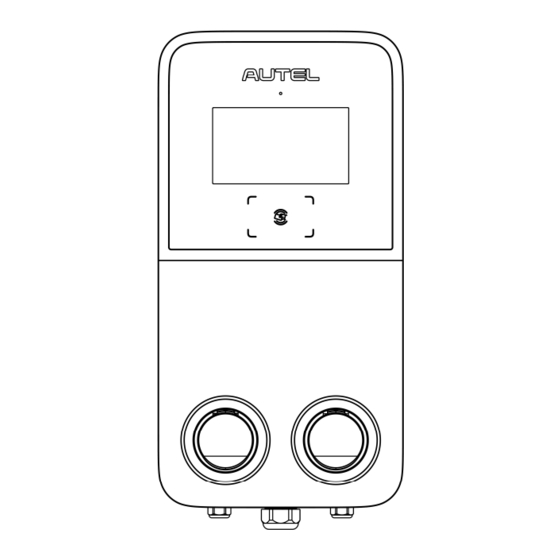
Page 10: Product Overview (Outside)
Product Overview (Outside) Ambient Light Sensor — detects ambient brightness Display RFID Reader LED Ring (Refer to Table 3-1 Indicator Descriptions) Socket Product Label Meter AC Inlet Hole Data Cable Entry Upper Mounting Screw Mounting Hole... - Page 11 Table 3-1 Indicator Descriptions Description Solid Green: The charging station is in standby mode. — An EV is connected. — A charge session has ended. — Flashing Green: The charging handle is unplugged. (Turns solid green after — 10 seconds.) The RFID card is used for authentication while the charging —...
-
Page 12: Product Overview (Inside)
Product Overview (Inside) Power Board (Bottom) GPS Antenna Power Control Board Energy Meter Auxiliary Power RS485 Terminal Block RCBO Ethernet Port Terminal Block SIM Card Socket NOTICE In the above illustration, the left describes the bottom inside of the charging station, and the right showcases the inside with the middle cover. -
Page 13: In The Box
In the Box Main Kit Charging Station Wall Dock 1 PC 1 PC Screw (M6 x 50) Wall Anchor (For wall-mounting only) (For wall-mounting only) 5 PCS 5 PCS Quick Reference Guide Packing List 1 PC 1 PC Nameplate (For pedestal-mounting only) 1 PC Pedestal Kit... -
Page 14: Recommended Tools
Quick Reference Guide Packing List 1 PC 1 PC Tool Kit Drilling Template Socket Wrench (For wall-mounting only) 1 PC 1 PC T10 Screwdriver 1 PC Recommended Tools Tape measure Pencil Power drill Spirit level Crimp connector Drilling bit Crimping plier (EVN16-18 Wire stripper (8 mm/18 mm) -
Page 15: Installation
Installation Preparing for Installation 4.1.1 Location Requirements For Wall-mounting: Install the charging station on a flat and vertical surface capable of supporting at least 25 kg. Install the charging station in a location that allows the charging cable to remain within its bending tolerance. -
Page 16: Checklist
4.1.2 Checklist The local installation regulations are identified and followed. All necessary permits are obtained from the local authority that has jurisdiction. The existing electrical load has been calculated to find the maximum operating current for the charging station installation. -
Page 17: Energy Management
Ensure that all parts are delivered according to the order. Refer to 3.4 In the Box. Do a visual inspection of the charging station and the parts for damage. In case any damage is found or the parts are not consistent with your order, contact the delivery and Autel support. -
Page 18: Mechanical Installation
Mechanical Installation There are two ways to mount the charging station: Mounting on a wall Mounting on a pedestal 4.3.1 Mounting on a Wall STEP 1 Place the drilling template against the wall as shown and level it using a spirit level. - Page 19 STEP 3 Hook the charging station on the wall dock by inserting the two mounting screws (B) on the back of the charging station into the two upper mounting holes (A). Slide the charging station downwards to engage the screws. STEP 4 Loosen the two M3 x 8 screws (A) at the bottom of the charging station...
- Page 20 STEP 5 Remove the eight M3 x 8 screws using the T10 Torx screwdriver. Set them aside. STEP 6 Flip the maintenance cover up. Then insert two M6 x 50 screws into the two lower holes. Tighten the screws to 5-7 Nm using the socket wrench to secure the charging station.
-
Page 21: Mounting On A Pedestal
4.3.2 Mounting on a Pedestal STEP 1 Build a foundation with the size of 460 x 300 x 250 mm (L x W x Trench and excavate an opening to accommodate the wiring conduit. STEP 2 conduit designated location. The conduit stub-up is recommended 100 mm above the surface at a minimum. - Page 22 STEP 4 Loosen the four M5 x 20 security screws on both sides using the T25 screwdriver to remove the upper and lower front covers. Set them aside. STEP 5 Place the pedestal onto the foundation, aligning it with the conduit stub-up and four mounting holes.
- Page 23 STEP 6 Remove the three M6 x 16 and two M6 x 25 screws from the pedestal using the socket wrench. Set them aside. NOTICE If any of the screws appears broken or otherwise damaged while removing, replace them with the spare ones in the package. STEP 7 Align the wall dock with the three mounting holes on the pedestal.
- Page 24 STEP 8 Hang the charging station onto the wall dock by aligning the two mounting screws (A) on the back of the charging station with the two holes (B) of the wall dock. STEP 9 Loosen the two M3 x 8 screws (A) at the bottom of the charging station using the T10 screwdriver and remove the faceplate (B).
- Page 25 STEP 10 Remove the eight M3 x 8 screws using the T10 screwdriver. Set them aside. STEP 11 Flip the maintenance cover up. Then insert two M6 x 25 screws into the two lower holes. Tighten the screws to 5-7 Nm using the socket wrench to secure the charging station.
-
Page 26: Power Supply Wiring
Power Supply Wiring NOTICE 16 mm² copper wires are recommended. Choose based on the power supply available, local electrical code, and the distance from the distribution box. Loosen the cable gland at the bottom of the charging station and feed the AC input cable through it. -
Page 27: Internet Connection
Internet Connection The MaxiCharger AC Ultra can access the Internet via Ethernet cable, cellular network or Wi-Fi. 4.5.1 Via Ethernet Cable NOTICE Use Cat5 and above network cable with twisted pair wires. Shielded cable is recommended. For outdoor installation, use a UV-stabilized network cable. -
Page 28: Via Wi-Fi
4.5.3 Via Wi-Fi To connect the charging station to the Internet via Wi-Fi, please finish the installation first and refer to 5.1 Initial Setups. Finishing Installation Ensure that all installation and wiring are secured and correct. Then flip the maintenance cover down. -
Page 29: Configuration
Configuration For the charging station to function, a series of setups must be completed prior to use. Switch on the power to the charging station. WARNING Risk of electric shock Only a certified installation engineer is allowed to configure the charging station. Initial Setups Select the language. - Page 30 Select the time zone. Tap Next to continue or Previous to return to the previous page. Select the maximum input current based on the ratings of the MaxiCharger and local grid capacity. Tap Complete to finish the initial setups or Previous to return to the previous page.
-
Page 31: Ocpp Settings
OCPP Settings On the Standby Screen, tap the “currency ($)” icon on the lower-left corner to enter the Cost Details Screen. On the Cost Details Screen, double tap the upper-left corner to enter the next page. Select Device Maintenance on the screen. - Page 32 NOTICE For safety reasons, please contact Autel technical support to reset the password. Tap Set Parameters to set the OCPP IP, OCPP URL address, port number, OCPP encryption method, and other parameters if needed.
-
Page 33: Operation
— The display will show that the EV is fully charged. — End the charge session by tapping the RFID card on the RFID reader again or via the Autel Charge app by tapping Stop on the Charging Screen. -
Page 34: Display Descriptions
2. Remove the charging handle from the charger socket outlet and the EV charging port. NOTICE If the EV charging handle is unplugged during the charge session, the charging station automatically disconnects the power supply. This stops all charging operations. -
Page 35: Authorization Screen
6.2.2 Authorization Screen Choose an authorization method to start a charge session — QR code, RFID card or credit card (optional). 6.2.3 Start Charging Screen 6.2.4 Charging Screen The Charging Screen will show the real-time charging progress, current power, charging duration, current cost, as well as volume. -
Page 36: Cost Details Screen
Error Screen The display shows different error messages depending on the error type. Resolve the problem(s) by following the on-screen instructions, contacting Autel technical support or trying another MaxiCharger. Below is an example for the error screen: If the charging handle is not available, the following screen may appear. -
Page 37: Troubleshooting
Troubleshooting The table below describes the most common faults when operating the charging station. Contact Autel technical support if the fault encountered is not in this table. Item Problems Solutions Use the multimeter to check whether the voltage on the power input is too high. -
Page 38: Technical Specifications
Technical Specifications Product Specifications Table 8-1 Product Specifications Item Description AC Power Output Rating 2 x 22 kW 400 V ± 15%, three-phase, 50 Hz AC Power Input Rating 230 V ± 10%, single-phase, 50 Hz Network Type TN and TT Circuit Breaker 40 A 400 VAC, three-phase (3P + N + PE) - Page 39 Item Description Communications Protocol OCPP 1.6J & OCPP 2.0.1 Mounting Wall-mounted or floor using a pedestal IP54 Enclosure Ratings IK10 Indoor or outdoor installation -30 to 50 °C Operating Temperature (Derating starts at 35 °C; output no less than 16A per connector at 50 °C) Storage Temperature -40 to 70 °C...
-
Page 40: Product Dimensions
Product Dimensions Pedestal Weight: 27.25 kg Pedestal Material: Stainless Steel SUS430... -
Page 41: Compliance
Compliance The product is in conformity with the following standards and/or other normative documents: EN 301 489-1 V2.2.3 EN 301 489-3 V2.1.1 EN 301 489-17 V3.2.4 EN 301 489-52 V2.1.1 EN 300 328 V2.2.2 EN 300 330 V2.1.1 EN 301 908-1 V13.1.1 EN 301 908-2 V13.1.1 EN 301 908 -13 V13.1.1 EN 301 511 V12.5.1... - Page 42 www.autelenergy.com...
Need help?
Do you have a question about the MaxiCharger AC Ultra and is the answer not in the manual?
Questions and answers