Table of Contents
Advertisement
Advertisement
Table of Contents

Related Manuals for Autel MaxiCharger AC Wallbox Home


Summary of Contents for Autel MaxiCharger AC Wallbox Home
- Page 1 MaxiCharger AC Wallbox Home Installation and Operation Manual...
- Page 2 All information, specifications and illustrations in this manual are based on the latest information available at the time of printing. Autel reserves the right to make changes at any time without notice. While information of this manual has been carefully checked for accuracy, no guarantee is given for the completeness and correctness of the contents, including but not limited to the product specifications, functions, and illustrations.
-
Page 3: Safety Messages
Safety Instructions The safety messages herein cover situations Autel is aware of. Autel cannot know, evaluate or advise you as to all of the possible hazards. You must be certain that any condition or service procedure encountered does not jeopardize your personal safety. - Page 4 Use 90 °C wire copper conductors only. Do not operate the equipment outside its operating temperature range of -40 to 131 °F (-40 to 55 °C). Incorrect installation and testing of the equipment could potentially damage the vehicle's ...
-
Page 5: Table Of Contents
CONTENTS SAFETY INFORMATION ................II SAFETY MESSAGES ..................II SAFETY INSTRUCTIONS ................II 1 USING THIS MANUAL ................... 1 ....................1 ONVENTIONS 2 GENERAL INTRODUCTION ................3 ................4 RODUCT VERVIEW ....................7 ODELS ..................8 PECIFICATIONS 3 INSTALLATION .................... 10 .................. -
Page 6: Using This Manual
Using This Manual This manual describes the installation and use of the MaxiCharger AC Wallbox Home. Prior to installation, read through this manual to be familiarized with the instructions of this MaxiCharger to ensure a successful installation and smooth operations. - Page 7 Important IMPORTANT indicates a situation which, if not avoided, may result in damage to the test equipment or vehicle. Example: IMPORTANT In Canada, a NEMA plug-in installation is only allowed with a 50 amp circuit. Hyperlink Hyperlinks or links that take you to other related articles, procedures, and illustrations are available in electronic documents.
-
Page 8: General Introduction
This manual will instruct you how to install and use this charger. Intended Use The MaxiCharger AC Wallbox Home is intended for the AC charging of EVs. It is intended for both indoor and outdoor use. DANGER If you use the equipment in any way other than described in this manual or other related documents, possible death, injury and damage to property can occur. -
Page 9: Product Overview
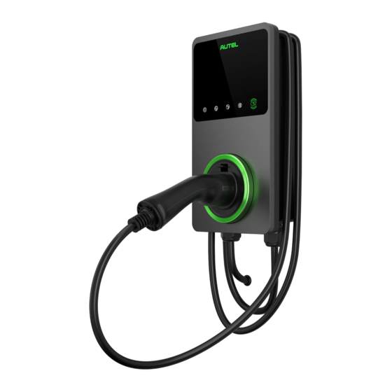
2.1 Product Overview Autel MaxiCharger AC Wallbox Home LED Indicators (from left to right): Power LED Internet Connection LED Charging LED Bluetooth Connection LED RFID LED EV Charging Cable Bottom AC Inlet Hole Bottom Ethernet Cable Port... - Page 10 Mounting Screws Rear AC Inlet Hole Rear Ethernet Cable Port Product Label 10. RJ45 Port 11. RS485 Port — connects the RS485 cables 12. Current Selector — adjusts the current for the charger...
- Page 11 LED Description Description Solid Green: The charger is on. Not Illuminated: The charger is off. Flashing Yellow: Data is being transmitted and/or firmware is Power LED upgrading. Solid Yellow: Firmware upgrade has failed. Solid Blue: Data transmission has failed; will illuminate green in ...
-
Page 12: Models
2.2 Models MaxiCharger AC Wallbox Home (Separate Holster) NEMA Plug-in Version Hardwire Version MaxiCharger AC wallbox Home Holster Connector... -
Page 13: Specifications
2.3 Specifications Item Description Maximum 7.6 kW (240 VAC @ 32 A model) AC Power Output Rating Maximum 9.6 kW (240 VAC @ 40 A model) Maximum 12 kW (240 VAC @ 50 A model) 208/240 V AC, 60 Hz, single phase @ 16 A, AC Power Input Rating 24 A, 32 A, 40 A, 48 A, 50 A Circuit Breaker Options (A) - Page 14 Item Description Sub-G (Auto Open the Tesla Optional, only available on chargers with built-in holster Charging Port) OCPP 1.6J Communication Protocols OCPP 2.0 (Optional, will be available soon) Mounting Wall-mounted or floor using a pedestal Enclosure Ratings NEMA 4, indoor or outdoor installation Operating Temperature -40 to 131 °F (-40 to 55 °C)
-
Page 15: Installation
Installation 3.1 Unpacking Make sure that all parts are delivered according to the order. Check the packaging for the following parts. Charging Station Wall Dock Screw (M6 x 50) Screw (M5 x 12) 2 PCS Wall Anchor Bottom Entry (5/16”) Power Conduit 2 PCS Plug (M32) - Page 16 Tool Kit Screwdriver (Type Screwdriver (Type T10) T25) Holster & Mounting Holster Wall Dock Screw (M6 x 50) Screw (M5 x 12) 3 PCS Wall Anchor (5/16”) 2 PCS NOTE The Holster & Mounting accessories are only applicable for the MaxiCharger AC Wallbox Home (Separate Holster) model.
-
Page 17: Preparing For Installation
3.2.1 Location Install your charger on a flat and vertical surface capable of supporting its weight (e.g., a finished wall or pedestal). The maximum weight of a MaxiCharger AC Wallbox Home is approximately 14.8 lbs. (6.7 kg). Install the charger in a location that allows the charging cable to remain within its bending tolerance. - Page 18 The recommended installation height is between 51 and 67 inches (1300 and 1700 mm). For NEMA plug-in installation, the NEMA outlet should be located at least 18 inches (460 mm) from the ground adjacent to the position where the charger will be mounted.
-
Page 19: Nema Plug-In Outlet
3.3 NEMA Plug-in Outlet This section introduces how to install a NEMA outlet if you do not have one already. WARNING Switch off the circuit breaker of the electrical outlet before installing your charger. If you already have a NEMA outlet, ensure that it complies with local electrical codes and has a designated circuit breaker and electrical wiring that are dimensioned appropriately. -
Page 20: Installing The Charger
3.4 Installing the Charger 3.4.1 NEMA Plug-in Installation To find the ideal mounting height of the charger: DANGER Risk of shock. Turn off the power to the outlet at the circuit breaker until the installation is completed. Find the wall stud nearest to the NEMA outlet using a wall stud finder. Draw a vertical line of approximately 20"... - Page 21 Place the wall dock with the bottom edge aligned with the horizontal line and the center holes aligned with the vertical line. Mark the two lower mounting holes (A) and remove the wall dock. Drill two 5/16" holes and insert two 5/16" diameter wall anchors into the lower mounting holes.
- Page 22 Attach the charger to the wall dock by inserting the mounting screws (D) on the back of the charger into the two upper mounting holes (C). Slide the charger downwards. Screw the M5 x 12 screw (E) into the hole at the bottom of the charger and tighten the screw to secure the charger using the screwdriver type T25.
- Page 23 3.4.2 Hardwired Installation The MaxiCharger AC Wallbox Home supports both rear entry and bottom entry wiring. Choose the most appropriate wiring entry for your charger based on the placement of the wiring. IMPORTANT Both the rear entry and bottom entry locations are on the left side of the charger. Ensure that you mount your charger in a location where the power supply wiring can be easily accessed on the left side.
- Page 24 For rear entry wiring, mark the cable exit where the AC input cable will come out from the wall. Ensure that the cable exit matches the wall dock notch per the diagram below.
- Page 25 Mounting the Wall Dock Drill two 5/16" holes and insert two 5/16" diameter wall anchors into the lower mounting holes. Attach the wall dock to the mounting location by screwing two M6 x 50 screws (B) into the lower mounting holes. Tighten the screws using the screwdriver type PH2 (not included in the package).
- Page 26 Removing the NEMA Cable (Optional) In case you need to replace the NEMA cable with a Hardwire, remove the NEMA cable by unscrewing the terminal screws per the diagram. Then loosen the cable gland and pull down the NEMA cable.
- Page 27 Power Supply Wiring IMPORTANT Use copper conductors with the maximum wire size of 6 AWG (16 mm²). Ensure that the screws for the terminal blocks are properly tightened. Ensure that there is no copper wire or debris left inside of the charger before switching ...
- Page 28 Bottom Entry Insert the AC input cable into the inlet hole (H).
- Page 29 Step 2 Strip the wires to 1/2" (12 mm). Connect the wires (L1, L2, and Ground) per the diagram and tighten each connector screw to 2 N·m (17.7 in·lbs). Reinstall the covers and tighten the screws. Refer to Step 4 Step 5 in NEMA Plug-in Installation to finish mounting the charger.
- Page 30 Connecting the Ethernet Cable Step 1 Bottom Entry Put the Ethernet cable with the RJ45 plug through the bottom Ethernet cable port (I). Rear Entry Pierce the rubber grommet and put the Ethernet cable through it. Make a RJ45 plug and connect it with the Ethernet cable.
- Page 31 Step 2 Plug the cable into the RJ45 port as shown. RS485 Cables Wiring (Optional) If you need to connect the RS485A and RS485B cables, insert the cables through the bottom Ethernet cable port (K) first. Then connect the cables to the RS485 port as specified on the terminal block, respectively.
- Page 32 Adjusting the Rated Current The MaxiCharger AC Wallbox Home allows you to manually set a lower maximum current using a current selector when installing your charger on a circuit rated lower than the maximum rating for your charger. Remove the covers and locate the current selector.
- Page 33 CAUTION To reduce the risk of fire, only connect your charger to a circuit with a branch circuit over- current protection of 125% of the selected maximum amperage setting of the device in accordance with ANSI/NFPA 70 (US) C22.2 NO 280 13 (Canada). Installing the Holster NOTE ...
- Page 34 Align the three connecting points (M) of the holster with the installation slots (L). Make sure they are connected securely. Screw the M5 x 12 screw (N) into the hole at the bottom of the holster and tighten the screw to secure the holster using the screwdriver type T25. Drape the charging cable over the top of the charger or holster and dock your EV connector in it.
-
Page 35: Operation
App Store; for Android users, you will be redirected to the Google Play. Open the Autel Charge app on your mobile device, and log in with your phone number or email. If you do not yet have an account, register with your phone number first. -
Page 36: Start Charging
Use the Autel Charge app by tapping Start on the Charge screen. — If you have set a charging schedule in the Autel Charge app, the charger will initiate — a charge session automatically as scheduled. -
Page 37: Troubleshooting And Service
Troubleshooting and Service 5.1 Troubleshooting Table Item Problems Solutions Check whether the QR code on the charger is consistent with the QR code on the The charger is successfully added, Installation Guide. If so, make sure the but the Bluetooth connection fails. Bluetooth is enabled on your mobile device;... - Page 38 Item Problems Solutions Check whether the EV charging cable is securely connected. Ensure the operating temperature is within the specified range on the Over-heating product label. Stop charging. Restart charging until it is within the operation temperature range.
-
Page 39: Service
5.2 Service If you cannot find solutions to your problems with the aid from the table above, please contact our technical support. AUTEL Website: www.autelenergy.com Phone: (844) 765-0150 Email: Autelenergy@autel.com Address: 36 Harbor Park Drive, Port Washington, New York, USA 11050... -
Page 40: Compliance
Compliance FCC regulatory conformance: This device complies with Part 15 of the FCC Rules. Operation is subject to the following two conditions: (1) This device may not cause harmful interference. (2) This device must accept any interference received, including interference that may cause undesired operation. - Page 41 (1) This device may not cause interference. (2) This device must accept any interference, including interference that may cause undesired operation of the device. Cet appareil est conforme à la norme CAN ICES-3 (B)/NMB-3 (B). Cet appareil contient des émetteurs / récepteurs exempt (s) de licence qui sont conformes aux RSS exemptes de licence d'Innovation, Sciences et Développement économique Canada.
- Page 42 Web: www.autelenergy.com...
Need help?
Do you have a question about the MaxiCharger AC Wallbox Home and is the answer not in the manual?
Questions and answers