Table of Contents
Advertisement
Trademarks
®
Autel
and MaxiCharger
registered in China, the United States and other countries. All other marks are trademarks
or registered trademarks of their respective holders.
Copyright Information
No part of this manual may be reproduced, stored in a retrieval system or transmitted, in
any form or by any means, electronic, mechanical, photocopying, recording, or otherwise
without the prior written permission of Autel.
Disclaimer of Warranties and Limitation of Liabilities
All information, specifications and illustrations in this manual are based on the latest
information available at the time of printing.
Autel reserves the right to make changes at any time without notice. While information of
this manual has been carefully checked for accuracy, no guarantee is given for the
completeness and correctness of the contents, including but not limited to the product
specifications, functions, and illustrations.
Autel will not be liable for any direct, special, incidental, indirect damages or any economic
consequential damages (including the loss of profits).
IMPORTANT
Before operating or maintaining this unit, please read this manual carefully, paying extra
attention to the safety warnings and precautions.
For Services and Support (24/7):
Web:
www.autelenergy.com
Tel: (844) 765-0150
Email:
evsupport@autel.com
Address: 36 Harbor Park Drive, Port Washington, New York, USA 11050
For technical assistance in all other markets, please contact your local selling agent.
®
are trademarks of Autel Intelligent Technology Corp., Ltd.,
i
Advertisement
Table of Contents

Related Manuals for Autel MaxiCharger Maxi US AC LW12


Summary of Contents for Autel MaxiCharger Maxi US AC LW12
- Page 1 All information, specifications and illustrations in this manual are based on the latest information available at the time of printing. Autel reserves the right to make changes at any time without notice. While information of this manual has been carefully checked for accuracy, no guarantee is given for the completeness and correctness of the contents, including but not limited to the product specifications, functions, and illustrations.
-
Page 2: Safety Messages
Safety Instructions The safety messages herein cover situations Autel is aware of. Autel cannot know, evaluate or advise you as to all of the possible hazards. You must be certain that any condition or service procedure encountered does not jeopardize your personal safety. - Page 3 Children should be supervised when around this equipment. Do not insert fingers or foreign objects into the electric vehicle connector. Do not use the equipment if the flexible power cord or EV cable is frayed, broken or otherwise damaged, or fails to operate.
- Page 4 THE SUITABILITY OF THE USE OF FLEXIBLE CORD IN ACCORDANCE WITH CE CODE, PART I, RULE 4-012, IS TO BE DETERMINED BY THE LOCAL INSPECTION AUTHORITY HAVING JURISDICTION C’EST À L’AUTORITÉ LOCALE COMPÉTENTE EN MATIÈRE D’INSPECTION QU’INCOMBE DE DÉTERMINER SI UN CORDON SOUPLE PEUT ÊTRE UTILISÉ CONFORMÉMENT À...
-
Page 5: Table Of Contents
CONTENTS SAFETY INFORMATION ....................... II SAFETY MESSAGES ......................II SAFETY INSTRUCTIONS ..................... USING THIS MANUAL ....................1 1.1 C ........................1 ONVENTIONS GENERAL INTRODUCTION ..................2 2.1 P ......................3 RODUCT VERVIEW 2.2 S ....................... 6 PECIFICATIONS INSTALLATION ......................8 3.1 U ........................ -
Page 6: Using This Manual
Using This Manual This manual describes the installation and use of the MaxiCharger AC Lite. Prior to installation, read through this manual to be familiarized with the instructions of this MaxiCharger to ensure a successful installation and smooth operations. 1.1 Conventions The following conventions are used. -
Page 7: General Introduction
General Introduction The MaxiCharger AC Lite is designed to charge a plug-in hybrid electric vehicle or an electric vehicle (hereinafter called EV) at your home or condo. Our chargers provide you with safe, reliable, fast, and smart charging solutions. This manual will instruct you how to install and use this charger. Intended Use The MaxiCharger AC Lite is intended for the AC charging of EVs. -
Page 8: Product Overview
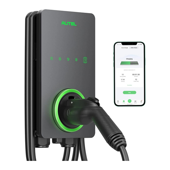
2.1 Product Overview MaxiCharger AC Lite LED Indicators (from left to right): Power LED Internet Connection LED Charging LED Bluetooth Connection LED RFID Reader Holster Connector EV Charging Cable Bottom AC Inlet Hole Bottom Ethernet Cable Port... - Page 9 Mounting Screws Rear AC Inlet Hole 10. Rear Ethernet Cable Port 11. Product Label 12. RJ45 Port 13. RS485 Port — connects the RS485 cables 14. Current Selector — adjusts the current for the charger...
- Page 10 LED Description Description Solid Green: The charger is on. Not Illuminated: The charger is off. Flashing Yellow: Data is being transmitted and/or firmware is Power LED upgrading. Solid Yellow: Firmware upgrade has failed. Solid Blue: Data transmission has failed; will illuminate green in five seconds.
-
Page 11: Specifications
2.2 Specifications Item Description Maximum 7.6 kW (240 VAC @ 32 A model) AC Power Output Rating Maximum 9.6 kW (240 VAC @ 40 A model) Maximum 12 kW (240 VAC @ 50 A model) 208/240 VAC, 60 Hz, single phase @ 16 A, 24 A, 32 A, AC Power Input Rating 40 A, 48 A, 50 A Circuit Breaker Options (A) - Page 12 Item Description Sub-G (Auto Open Optional, only available on chargers with built-in holster Tesla Charging Port) OCPP 1.6J Communication Protocols OCPP 2.0 (Optional, will be available soon) Mounting Wall-mounted or floor using a pedestal NEMA 4X, indoor or outdoor installation Enclosure Ratings (NEMA cable length: 300 mm) Operating Temperature...
-
Page 13: Installation
Installation 3.1 Unpacking Make sure that all parts are delivered according to the order. Check the package for the following parts. Charging Station Wall Dock Screw (M6 x 50) Screw (M5 x 12) 2 PCS Wall Anchor Bottom Entry (5/16”) Power Conduit 2 PCS Plug (M32) -
Page 14: Electrical Design
3.2 Electrical Design 3.2.1 Upstream Wiring Charging stations are considered continuous load devices (EVs draw maximum load for long durations); therefore, electrical branch circuits must be sized at 125% of the load for North American installations, in accordance with National Electric Code (NEC) requirements. - Page 15 208 VAC Panel Main Breaker PE Bus Local Service or Sub Panel 10. Input Terminal Block 11. Output Terminal Block 3.2.3 Grounding Requirements The charger must be connected to a grounded, metal, and permanent wiring system. An equipment-grounding conductor must be run with circuit conductors and connected to an equipment-grounding terminal or lead on the charger.
-
Page 16: Preparing For Installation
3.3 Preparing for Installation 3.3.1 Location Install the charger on a flat and vertical surface capable of supporting its weight (e.g., a finished wall or pedestal). The maximum weight of a MaxiCharger AC Lite is approximately 15 lbs. (7 kg). Install the charger in a location that allows the charging cable to remain within its ... - Page 17 The recommended installation height is between 51 and 67 inches (1300 and 1700 mm). For NEMA plug-in installation, the NEMA outlet should be located at least 18 inches (460 mm) from the ground adjacent to the position where the charger will be mounted.
-
Page 18: Nema Plug-In Outlet
3.4 NEMA Plug-in Outlet This section introduces how to install a NEMA outlet if needed. WARNING Switch off the circuit breaker of the electrical outlet before installing the charger. Ensure the NEMA outlet complies with local electrical codes and has a designated circuit breaker and electrical wiring that are dimensioned appropriately. -
Page 19: Installing The Charger
3.5 Installing the Charger 3.5.1 NEMA Plug-in Installation To find the ideal mounting height of the charger: DANGER! Risk of shock. Turn off the power to the outlet at the circuit breaker until the installation is completed. Find the wall stud nearest to the NEMA outlet using a wall stud finder. Draw a vertical line of approximately 20"... - Page 20 Place the wall dock with the bottom edge aligned with the horizontal line and the center holes aligned with the vertical line. Mark the two lower mounting holes (A) and remove the wall dock. Drill two 5/16" holes and insert two 5/16" diameter wall anchors into the lower mounting holes.
- Page 21 Attach the charger to the wall dock by inserting the mounting screws (D) on the back of the charger into the two upper mounting holes (C). Slide the charger downwards. Screw the M5 x 12 screw (E) into the hole at the bottom of the charger and tighten the screw to secure the charger using the type T25 screwdriver.
- Page 22 3.5.2 Hardwired Installation The MaxiCharger AC Lite supports both rear entry and bottom entry wiring. Choose the most appropriate wiring entry for your charger based on the placement of the wiring. IMPORTANT Both the rear entry and bottom entry locations are on the left side of the charger. Ensure that you mount your charger in a location where the power supply wiring can be easily accessed on the left side.
- Page 23 Place the wall dock with the center holes aligned with the vertical line. Mark the two lower mounting holes (A) and remove the wall dock. For rear entry wiring, mark the cable exit where the AC input cable will come out from the wall.
- Page 24 Mounting the Wall Dock Drill two 5/16" holes and insert two 5/16" diameter wall anchors into the lower mounting holes. Attach the wall dock to the mounting location by screwing two M6 x 50 screws (B) into the lower mounting holes. Tighten the screws using the type PH2 screwdriver (not included in the package).
- Page 25 Removing the NEMA Cable (Optional) In case that the NEMA cable is to be replaced with a Hardwire, remove the NEMA cable by unscrewing the terminal screws according to the diagram. Then loosen the cable gland and pull down the NEMA cable. Power Supply Wiring IMPORTANT ...
- Page 26 Screw the nut into the conduit fitting.
- Page 27 Remove the lower-left cable gland and install the bottom entry power conduit plug (G) to the charger. Bottom Entry Insert the AC input cable into the inlet hole (H).
- Page 28 Step 2 Strip the wires to 1/2" (12 mm). Connect the wires (L1, L2, and Ground) according to the diagram and tighten each connector screw to 2 N·m (17.7 in·lbs). Reinstall the covers and tighten the screws. Refer to Step 4 Step 5 in NEMA Plug-in Installation to finish mounting the charger.
- Page 29 Connecting the Ethernet Cable Step 1 Bottom Entry Put the Ethernet cable with the RJ45 plug through the bottom Ethernet cable port (I). Rear Entry Pierce the rubber grommet and put the Ethernet cable (J) through it. Make a RJ45 plug and connect it with the Ethernet cable (J).
- Page 30 Step 2 Plug the cable into the RJ45 port as shown. RS485 Cables Wiring (Optional) Insert the RS485 cables through the bottom Ethernet cable port (K) first. Then connect the cables to the RS485 port as specified on the terminal block, respectively.
- Page 31 Adjusting the Rated Current The MaxiCharger AC Lite can set a lower maximum current using a current selector when installing the charger on a circuit rated lower than the maximum rating. Remove the covers and locate the current selector. Use a flathead screwdriver to set the rotary switch to the appropriate position per the diagram below.
- Page 32 When the current of the charger is set lower than the maximum rating, choose the correct current value from the Amperage Labels and affix it over the existing label on the charger. CAUTION To reduce the risk of fire, only connect the charger to a circuit with a branch circuit over- current protection of 125% of the selected maximum amperage setting of the device in accordance with ANSI/NFPA 70 (US) CSA C22.1 (Canada).
-
Page 33: Operation
To add the charger Scan the QR code below to download the Autel Charge app to a mobile device from the Google Play or App Store. For iOS users, you will be redirected to the App Store; for Android users, you will be redirected to the Google Play. -
Page 34: Start Charging
Plug the connector into the EV charging port. Choose one of the following ways to start a charge session: If the Auto Start function is enabled in the Autel Charge app, the charger will — automatically start charging once the connector is properly connected. -
Page 35: Troubleshooting And Service
Troubleshooting and Service 5.1 Troubleshooting Table Item Problems Solutions Check whether the QR code on the charger is consistent with the QR code on the Quick The charger is successfully added, Reference Guide. If so, make sure the but the Bluetooth connection fails. Bluetooth is enabled on your mobile device;... - Page 36 Item Problems Solutions Check whether the EV charging cable is securely connected. Ensure the operating temperature is within the specified range on the Over-heating product label. Stop charging. Restart charging until it is within the operation temperature range.
-
Page 37: Compliance
Compliance FCC regulatory conformance: This device complies with Part 15 of the FCC Rules. Operation is subject to the following two conditions: (1) This device may not cause harmful interference. (2) This device must accept any interference received, including interference that may cause undesired operation. - Page 38 This device contains licence-exempt transmitter(s)/receiver(s) that comply with Innovation, Science and Economic Development Canada's licence-exempt RSS(s). Operation is subject to the following two conditions: (1) This device may not cause interference. (2) This device must accept any interference, including interference that may cause undesired operation of the device.
Need help?
Do you have a question about the MaxiCharger Maxi US AC LW12 and is the answer not in the manual?
Questions and answers