Table of Contents

Subscribe to Our Youtube Channel
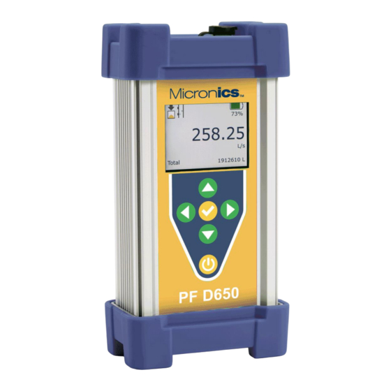
Related Manuals for Micronics Portaflow D650


Summary of Contents for Micronics Portaflow D650
- Page 1 Portaflow D650 Non-Contacting Doppler Flow Meter User Manual Micronics Ltd, Kenfig Industrial Estate Margam, Port Talbot, SA13 2PW, UK Telephone: +44(0)1628 810456 E-mail: sales@micronicsltd.co.uk www.micronicsflowmeters.com...
- Page 3 Micronics PF D650 User Manual DOCUMENT AUTHORITY Issue Date Originator Approved 03/12/2024 Micronics Ltd Issue 1.0 03/12/2024 Page i...
-
Page 4: Table Of Contents
PF D650 User Manual Micronics Contents CARRY CASE............................. 1 INTERNAL BATTERY ......................... 2 CHARGER ............................2 TRANSDUCER CONNECTIONS ......................3 USB-C CONNECTIONS (CHARGER, MODULES) ................3 TRANSDUCER & CABLE ........................3 KEYPAD ............................4 POWER ON/OFF & CHARGING ......................6 MENU STRUCTURE .......................... -
Page 5: Carry Case
Micronics PF D650 User Manual CARRY CASE The PF D650 is packaged in an orange IP67 carry case with protective molded foam. The picture below shows how the various components included with the PF D650 are populated into the molds:... -
Page 6: Internal Battery
INTERNAL BATTERY WARNING: THE PF D650 INCLUDES A LITHIUM-ION BATTERY. FOR YOUR SAFETY, OPERATE ONLY WITHIN THE SPECIFICATIONS PUT FORTH BY MICRONICS. • A built-in rechargeable lithium-ion battery supplies power for approximately 15 hours of continuous operation when fully charged. -
Page 7: Transducer Connections
Micronics PF D650 User Manual TRANSDUCER CONNECTIONS The transducer cable is connected via the IP67 socket on the top of the PF D650: USB-C CONNECTIONS (CHARGER, MODULES) USB-C is a USB connector system with a rotationally symmetrical connector. Devices connected to USB-C may be hosts or peripherals. -
Page 8: Keypad
PF D650 User Manual Micronics KEYPAD Keypad layout and functionality is as shown and described below: UP Arrow: • From Main screen – Navigate to Messages page • In programming menus – navigate up in the menus • In pop-out menus – change the selection or... - Page 9 Micronics PF D650 User Manual KEYPAD (CONT.) Keypad layout and functionality continues as shown and described below: CHECK Button: • From Main screen – not applicable • In programming menus – will move the cursor back one level. Example: if in the Units/Mode sub menu, CHECK will move back to Main Menu.
-
Page 10: Power On/Off & Charging
Press and hold the POWER button for 3-5 seconds to turn the meter on. When powering on, the meter will display a boot-up screen with the Micronics logo. When powering off, press the POWER button and the meter will display a pop-up message that asks for input on which power mode to use. -
Page 11: Menu Structure
Micronics PF D650 User Manual MENU STRUCTURE The structure of the menu pages on the PF D650 is as follows. Using the buttons as shown below will navigate between the different menus: 1 – Inserting a USB drive while on this page will download the 24 hr log data to the USB in .csv format... -
Page 12: Main Display
PF D650 User Manual Micronics MAIN DISPLAY The main display’s top row shows icons for the status of the data logger, signal quality, charging status, battery fuel gauge percentage, and data logging download status when a USB-C drive is inserted while on this page. -
Page 13: Status
Micronics PF D650 User Manual STATUS Pressing DOWN from the Main Display will take you to the Status page. This page shows the status of the measurement itself, Flow Velocity currently measured, Flow Rate currently measured, Min Flow (read- only) as set in the Calibration menu, Signal strength, Exp. SOS (Expected fluid Speed Of Sound), and Meas. -
Page 14: Password
Press the CHECK button to accept the password and proceed to the Main Menu, or, press the POWER button to return to the Main Display. IMPORTANT: IF YOU HAVE MISPLACED YOUR PASSWORD, CONTACT MICRONICS FOR ASSISTANCE RECOVERING IT. Page 10 Issue 1.0 03/12/2024... -
Page 15: Main Menu
Micronics PF D650 User Manual MAIN MENU Pressing RIGHT from the Main Display (Set Password in Special Functions = 0000) or CHECK from the Password pop-out (Set Password ≠ 0000) will bring you to the Main Menu screen. The Main Menu functions to provide a simple, easy-to-understand starting point to navigate the programming parameters. - Page 16 PF D650 User Manual Micronics UNITS/MODE (CONT.) Flow – Select engineering units for the flow rate on the Main Display and Data Log. Options: Option Description Option Description USG/d US gallons per day liters per day USG/h US gallons per hour...
-
Page 17: Calibration
Micronics PF D650 User Manual CALIBRATION Mode – Read-only. Shows the selected Mode from the Units/Mode menu. Pipe ID – Enter the Pipe ID for the pipe the sensor is clamped on to. This allows for an accurate conversion from the measured signal (velocity) to flow rate. -
Page 18: Data Logging
File Format – Choose the file format for downloading the log. Default = .LG2. Options = .LG2, .CSV. LG2 format is used for viewing the logged data with the free Micronics Logger Software. CSV format is used for importing into spreadsheet software like Microsoft Excel. This parameter can be changed at any time. -
Page 19: Retrieving Log File
Micronics PF D650 User Manual SLEEP LOGGING to log in the low power state. Only valid for Intervals ≥ 30s. See specifications section for details on estimated battery life in sleep logging mode. IMPORTANT: IT IS STRONGLY ENCOURAGED TO DELETE THEN START THE DATA LOG AFTER MAKING ALL YOUR PARAMETER CHANGES IN THE METER. - Page 20 USB-C drive. When prompted on the screen via Insert USB, insert your USB-C drive into the meter, and the PF D650 will save the file. Micronics technical support will occasionally request this waveform file in order to help diagnose and resolve measurement questions.
-
Page 21: Battery Info
CONFIGURATION The Configuration page shows the serial number of the PF D650, and the firmware versions of the utility board, transit time board, and bootloader. Micronics may ask for this information to help diagnose measurement questions. Issue 1.0 03/12/2024 Page 17... -
Page 22: Sensor Mounting Location
PF D650 User Manual Micronics SENSOR MOUNTING LOCATION The position of the sensor is one of the most important considerations for accurate flow measurement. The same location guidelines apply to Doppler as they do for most other flow meter technologies. -
Page 23: Sensor Mounting
Micronics PF D650 User Manual IMPORTANT NOTE: IN SOME CASES, LONGER STRAIGHT RUNS MAY BE NECESSARY WHERE THE TRANSDUCERS ARE PLACED DOWNSTREAM FROM DEVICES WHICH CAUSE UNUSUAL FLOW PROFILE DISRUPTIONS OR SWIRL. FOR EXAMPLE: MODULATING VALVES, OR TWO ELBOWS IN CLOSE PROXIMITY AND OUT OF PLANE. - Page 24 Warm temperatures, moisture and vibration will accelerate this process. Super Lube ® as supplied with the PF D650 (and available from Micronics or home improvement stores) is recommended for semi-permanent installations.
- Page 25 Micronics PF D650 User Manual SENSOR MOUNTING/COUPLING RECOMMENDATIONS Issue 1.0 03/12/2024 Page 21...
-
Page 26: Common Questions And Answers
PF D650 User Manual Micronics COMMON QUESTIONS AND ANSWERS The pipe vibrates. Will it affect the flow meter? Common vibration frequencies are far lower than the sonic frequencies used by the flow meter and will not normally affect accuracy or performance. However, applications where very weak Doppler signal is present (when sensitivity is adjusted to maximum and signal strength is low), accuracy may be affected by pipe vibration, or the flow meter may show readings under no-flow conditions. - Page 27 ISO 9000 or similar quality management systems may require periodic and verifiable recalibration of flow meters. PF D650 Doppler Flow Meters may be returned to Micronics for factory calibration and issue of a new NIST traceable certificate. Refer to the ‘Product Return Procedure’ section of this manual for return instructions.
-
Page 28: Product Return Procedure
Instruments may be returned to Micronics for service or warranty repair. Obtain an RMA Number from Micronics - Before shipping a product to the factory please contact Micronics by telephone, fax or email to obtain an RMA number (Returned Merchandise Authorization). This ensures fast service and correct billing or credit. -
Page 29: Limited Warranty
Micronics warrants, to the original purchaser, its products to be free from defects in material and workmanship for a period of two years from date of invoice. Micronics will replace or repair, free of charge, any Micronics product if it has been proven to be defective within the warranty period. -
Page 30: Specifications
USB-C flash drive (included) 12 million point capacity, configurable for velocity or flow rate, date and time stamped, configurable format for Micronics Logger Software (LG2) or CSV, Data Logger: available intervals of 10 s, 30 s, 1 min, 2 min, 5 min, 10 min, 15 min, 30 min, and 1 hr Can be deployed in sleep-logging mode for extended battery duration. - Page 31 Micronics PF D650 User Manual Transducer Specifications Clamp-on, single-head ultrasonic for pipes from 12.7 mm to 4.6 m ID (0.5 Standard Model PSE4-A2: in to 15 ft) with 3.4 m (12 ft) shielded dual-coaxial cable and latching connector Sensor Mounting Kit: Stainless steel pipe clamp and 3.0 fl oz coupling compound...
-
Page 32: Appendix A - Conversion Table
PF D650 User Manual Micronics APPENDIX A - CONVERSION TABLE CONVERSION GUIDE FROM MULTIPLY BY US GALLONS CUBIC FEET 0.1337 US GALLONS IMPERIAL GALS 0.8327 US GALLONS LITRES 3.785 US GALLONS CUBIC METERS 0.003785 LITRES/SEC 15.85 LITRES CUBIC METERS 0.001... -
Page 33: Appendix B - Pipe Charts
Micronics PF D650 User Manual APPENDIX B - PIPE CHARTS Ductile Ir on Pipe - Standard Classes Size OUTSIDE Clas s Class Class C lass C lass C lass C la ss C EMEN T LIN IN G IN CH D IA. - Page 34 PF D650 User Manual Micronics Stainless Steel, Hastelloy "C" & Titanium Pipe Pipe Pipe Scheule 5 S (a) Schedule 10 S (a) Schedule 40 S Schedule 80 S Size O.D. I.D. WALL I.D. WALL I.D. WALL I.D. WALL ½ .840 .710...
- Page 35 Micronics PF D650 User Manual Cast Iron Pipe - ASA Standard Pipe Pipe Class 50 Class 100 Class 150 Class 200 Class 250 Class 300 Class 350 Size O.D. WALL I.D. WALL I.D. WALL I.D. WALL I.D. WALL I.D. WALL I.D.
- Page 36 PF D650 User Manual Micronics Copper Tubing Pipe Copper & Brass Pipe Aluminum Size O.D. I.D. WALL O.D. I.D. WALL O.D. I.D. WALL O.D. I.D. WALL O.D. I.D. WALL ½" 0.625 0.527 0.049 0.625 0.545 0.040 0.625 0.569 0.028 0.840 0.625...
Need help?
Do you have a question about the Portaflow D650 and is the answer not in the manual?
Questions and answers