Table of Contents
Advertisement
Quick Links
Advertisement
Table of Contents
Troubleshooting

Subscribe to Our Youtube Channel
Related Manuals for Micronics U3000


Summary of Contents for Micronics U3000
- Page 1 Micronics U3000/4000 Ultrasonic Flowmeter User Manual Issue 2.0...
-
Page 3: Table Of Contents
1.4.2 Keypad 1.4.3 Power supply 1.4.4 Expansion modules (U4000 only) 2: Installation 2.1 Safety Precautions and Warnings 2.2 Installing the U3000/U4000 instrument 2.2.1 Positioning the instrument 2.2.2 Mounting the instrument 2.2.3 Connecting the instrument 2.3 Installing The Ultrasonic Transducers 2.3.1 Transducer positioning 2.3.2 Preparation... - Page 4 4.7.1 How to print logged data using the RS232 printer 4.8 Operation with the Calec®ST Energy Totaliser 4.8.1 Pulse output 4.8.2 Connecting the U3000/U4000 to the Calec® ST Energy Totaliser 4.8.3 Configuring the U3000/U4000 4.8.4 Configuring the Calec® ST Energy Totaliser 5: Maintenance &...
-
Page 5: 1: General Description
13mm up to 2000mm and constructed of almost any material. The instrument will also operate over a wide range of fluid temperatures. The basic features of the U3000 and U4000 are identical. However, the standard U4000 can also perform data logging, has RS232 and USB communications interfaces. -
Page 6: Principles Of Operation
1: General Description Both the U3000 and U4000 have ‘A’ and ‘B’ model options, which refer to the transducer type provided. Thus a U3000A will be supplied with type ‘A’ transducers which are designed to work with pipe diameters between 13mm - 115mm;... -
Page 7: Supplied Hardware
The U3000/U4000 system employs two ultrasonic transducers attached to the pipe carrying the liquid and compares the time taken to transmit an ultrasound signal in each direction. If the sound characteristics of the fluid are known, the instrument’s microprocessor can use the results of the transit time calculations to... -
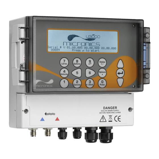
Page 8: U3000/U4000 Instrument
232 or EIA/RS-485 physical layer. U3000/U4000 Instrument The U3000/U4000 is a microprocessor controlled instrument operated through a menu system using an inbuilt LCD display and keypad. It can be used to display the instantaneous fluid flow rate or velocity, together with totalised volumes. -
Page 9: Keypad
1.4. U3000 Keypad Scroll UP ENTER (SELECT) Scroll DOWN Numerical keypad Scroll LEFT Scroll RIGHT with dual function keys U4000 Keypad Scroll UP ENTER (SELECT) Scroll DOWN Scroll LEFT Scroll RIGHT Figure 1.4 U3000/U4000 Keypad U3000/U4000 User Manual (Issue 2.0) -
Page 10: Power Supply
The U3000/U4000 menus are arranged hierarchally with the MAIN MENU being at the top level. Menu navigation is achieved by three keys located on the right hand side of the keypad which are used to scroll UP and DOWN a menu list and SELECT a menu item. -
Page 11: 2: Installation
Where, for operational reasons, it is not possible to mount the instrument this close to the sensors, bespoke cables of up to 100m can be provided – consult Micronics Ltd for further information and availability. A suitable mains supply must be available to power the instrument (an optional 24V a.c./d.c. supply module is available). - Page 12 M4 Screw Slot 198mm Cable connections All power and control cables enter through cable glands located on the bottom of the instrument and connect to terminal blocks as shown. Figure 2.1 U3000/U4000 Mounting and connection details U3000/U4000 User Manual (Issue 2.0)
-
Page 13: Connecting The Instrument
A Mini-USB connector is available at the left-hand side of the enclosure to which the USB cable provided can be attached, as shown in Figure 2.2. The free end of the USB cable can be plugged directly into any PC USB port. U3000/U4000 User Manual (Issue 2.0) -
Page 14: Installing The Ultrasonic Transducers
Installing The Ultrasonic Transducers 2.3.1 Transducer positioning In many applications an even flow velocity profile over The U3000/U4000 equipment expects a uniform flow profile a full 360° is unattainable due, for example, to the as a distorted flow will produce unpredictable measurement presence of air turbulence at the top of the flow and errors. -
Page 15: Preparation
– as shown in Figure 2.4. Once the guide rail assembly is fully assembled the transducers are locked into position by tightening two thumb screws which are themselves then secured by M5 locking nuts. U3000/U4000 User Manual (Issue 2.0) -
Page 16: Attaching The Guide Rail To The Pipe
Tighten the thumb screw (clockwise) until the transducer is locked to the top of the guide rail (to avoid the acoustic couplant from touching the pipe). Figure 2.7 Figure 2.8 U3000/U4000 User Manual (Issue 2.0) - Page 17 10. Finally lock the thumb screws in position by fitting the two M5 locknuts supplied. 11. Ensure the transducer signal cables are correctly connected to the U3000/U4000 instrument – i.e. with the RED cable is connected to the upstream transducer connector and the BLUE cable to the downstream transducer connector.
-
Page 18: Installing The Usb Virtual Com. Port (U4000 Only)
The USB connection requires a virtual com port to be installed on the computer. The necessary driver can be provided by Micronics or downloaded from http://www.ftdichip.com/Drivers/VCP.htm. Access the above url and download the driver for your particular operating system. The download takes the form of a zip file. -
Page 19: 3: Operating Procedures
How to download saved data to a PC – Paragraph 4.5 RS232 set-up – Paragraph 4.7.1 USB set-up – Paragraph 2.4 How to print data – Paragraph 4.7 How to use with Calec®ST Energy Totaliser – Paragraph 4.8 U3000/U4000 User Manual (Issue 2.0) -
Page 20: Setting-Up The Instrument
3: Operating Procedures Setting-up the Instrument The procedures outlined below apply to both the U3000 and U4000, unless otherwise indicated. Key Point: When the instrument used for the first time the operator has free access to all the set-up and operating menus until the instrument is put into FLOW READING operation, where-upon all the menus become password protected. -
Page 21: Enabling/Disabling The Backlight
To update the date/time parameters: Set Date & Time : dd-mm-yy hh:mm:ss Calibrate 4-20mA Set the required Date & Time as described Pulse output : Off Paragraph 3.1.1. Backlight : On-Permanently Factory settings Change Language Exit U3000/U4000 User Manual (Issue 2.0) -
Page 22: Using The Quick Start Menu
The Quick Start menu gathers various data for the site to be monitored and returns details of the transducer configuration that must be applied when mounting the transducers on the pipe. Before you can use the U3000/U4000 system you need to obtain the following details – this information is required when setting up the Quick Start menu: •... - Page 23 If the material is not listed select Other and enter the propagation rate of the pipe Mild Steel wall material in metres/sec. Contact S' less Steel 316 Micronics if this is not known. S' less Steel 303 Plastic Cast Iron Ductile Iron...
- Page 24 Note: Do not press ENTER until the transducers are fitted and connected to the instrument. Password Control After data has been entered for the first time, the U3000/U4000 password control feature is ‘enabled’ when you exit from Quick start to the FLOW READING screen. This prevents unauthorised tampering of the set- up data.
-
Page 25: Instrument Calibration
Key Point: In order to cancel any applied offset you must either read the flow via Quick Start or switch the instrument OFF & ON. Any value that you trim-out using the offset adjustment will be added/subtracted from the flow reading across the whole range. U3000/U4000 User Manual (Issue 2.0) -
Page 26: Adjusting The Calibration Factor
Run the totaliser to measure the total flow over a 30-60 minute period, and note the total flow indicated by the reference flow meter over the same period. Calculate the % error between the U3000/U4000 instrument and reference meters. If the error is greater than ±1% calibrate the U3000/U4000 as detailed below. -
Page 27: Adjusting The Damping Factor
Press ENTER to apply the change. 30 seconds 50 seconds 100 seconds Key Point: If the damping factor is set too high the value displayed may appear stable but might exhibit large step changes when the value is updated. U3000/U4000 User Manual (Issue 2.0) -
Page 28: Outputs
3: Operating Procedures Outputs Both the U3000 and U4000 have configurable Current, Pulse and Alarm outputs. 3.4.1 Current output Note: Where long cable runs are necessary, or noise pickup is causing unstable flow readings, the use of two core screened cable, such as BELDEN 9501 060U500, or similar, is recommended for use with the 4-20mA current output. - Page 29 11. Upon completion press ENTER to return to the FLOW READING screen. How to convert the measured current to flow rate Assume the maximum flow rate is (l/min) and the minimum flow rate is ‘0’ (l/min), as shown. [0-16mA scale] [0-20mA scale] [4-20mA scale] I (mA) U3000/U4000 User Manual (Issue 2.0)
-
Page 30: Pulse Output
Select On and press ENTER. Pulse width (ms) Exit A Pulse output is ON message will appear in the second line of the display. Select Exit and press ENTER to return to the FLOW READING screen. U3000/U4000 User Manual (Issue 2.0) -
Page 31: Alarm Outputs
3: Operating Procedures 3.4.3 Alarm outputs Both the U3000 and U4000 models contain two programmable alarm outputs that are interfaced by opto- isolated relays. The relay contacts are rated at a 48V (maximum voltage across the open contacts) and 500mA (maximum continuous current through the closed contacts). - Page 32 The ALARM SETTINGS screen should be Reset +Total displayed, as shown below. Reset –Total Calibration factor 1.000 Roughness factor 0.010 Alarm Settings Max Pulse Freq (Hz) 10.00 Flow at Max Frequency : 200.00 Calculated Pulse Value: 2.00 Diagnostics Exit U3000/U4000 User Manual (Issue 2.0)
-
Page 33: How To Measure Totalised Flows (Manually)
Reset +Total Note and record the current time. Reset –Total 10. Select Totaliser and change it to Run. Press ENTER. Totaliser is set to Run. Note: the totalisers begin to count up as soon as U3000/U4000 User Manual (Issue 2.0) - Page 34 If you want to stop the totaliser temporarily for operational reasons, set the Totaliser option to Stall in the FLOW READING OPTIONS screen as described above. This will stop the totaliser operation without affecting its current values. U3000/U4000 User Manual (Issue 2.0)
-
Page 35: 4: Data Logging & Communications (U4000)
QuickStart site. It allows Dim: mm you to either delete or save the existing log, or cancel the START NOW request. Press to confirm deletion Press to save log and continue Press to cancel U3000/U4000 User Manual (Issue 2.0) - Page 36 If you wish to monitor the logging progress at any time while you are operating in FLOW READING mode without interfering with the logging operation: Press the Logger function key as described above to switch to the REAL TIME LOGGER screen. Select View log as text or View log as graph, as required. U3000/U4000 User Manual (Issue 2.0)
-
Page 37: How To Set Up Automatic (Timed) Logging Mode
Select Stop date & time and enter the View log as graph START NOW date and time you wish logging to cease. Set Auto start Note this must be later than the start time. Clear log Exit U3000/U4000 User Manual (Issue 2.0) - Page 38 Graph Y axis max. : 50 instrument’s memory and can be viewed at Log Totals : +Total any time as described above. View log as text View log as graph STOP NOW Set Auto start Clear log Exit U3000/U4000 User Manual (Issue 2.0)
-
Page 39: How To Log Directly To A Pc
View log as graph and one editable site name (default Graph Y axis max. 1.00 EmptySite1). Select Choose from Download log list of sites and select one of these Clear log site names to download. Exit U3000/U4000 User Manual (Issue 2.0) -
Page 40: Working With Portagraph
2.4). Working With Portagraph II Micronics Ltd supplies the ‘Portagraph II Downloading and Graphing’ software to make it easy for the user to downloading logged data to a PC. This software application automatically connects to the U4000 via the RS232 or USB serial interface. Logged data can then be downloaded and analysed using the Portagraph II graphing capability, or exported to Microsoft Excel®... - Page 41 Bluetooth Printer Exit Select Send from the SETUP RS232/USB SETUP RS232/USB DD-MM-YY HH:MM:SS screen. The printer should now start printing. Send The message screen will be displayed Exit while printing takes place (see next page). U3000/U4000 User Manual (Issue 2.0)
-
Page 42: Operation With The Calec®St Energy Totaliser
(hot side) and another to the return pipe (cold side). The temperature difference ( = Thot - Tcold), measured by the Calec® ST Energy Totaliser, together with the pulse input from the U3000/U4000, allows the Calec® ST Energy Totaliser to calculate and display the accumulated Energy absorbed by the heating system. - Page 43 2.00 Diagnostics 12. Select Exit and press ENTER to return to Exit the FLOW READING screen. The message ‘Frequency Pulse is ON’ should now be displayed on the status line of the display (line 2). U3000/U4000 User Manual (Issue 2.0)
-
Page 44: Configuring The Calec® St Energy Totaliser
Two parameters need to be entered to allow operation with the U3000/U4000. These are: Maximum Input Frequency The Maximum Input Frequency should be the same as that set in the U3000/U4000, i.e. 10Hz or 200Hz. Volume per pulse (Imp) The Volume per pulse value should be the same as that indicated in the U3000/U4000 Calculated Pulse Value. -
Page 45: 5: Maintenance & Repair
The instrument and sensors should be calibrated at least once every 12 months. Contact Micronics or your local service agent for details. When returning product to Micronics make sure it is clean and please notify Micronics if the instrument has been in contact with any hazardous substances. - Page 46 5: Maintenance & Repair U3000/U4000 User Manual (Issue 2.0)
-
Page 47: 6: Troubleshooting
• Very hot pipe almost turns water to steam and therefore exhibits the wrong speed characteristics – could be due to reduced pipe pressure. • Flashover – liquid turns into a gas because of lower than required pressure. U3000/U4000 User Manual (Issue 2.0) -
Page 48: General Troubleshooting Procedure
- the pipe diameter is within specifications of the selected transducers. - the pipe is completely full. - the pipe surface is not corroded, or protective surface loose. - no particles in the fluid. Figure 6.1 Troubleshooting chart U3000/U4000 User Manual (Issue 2.0) -
Page 49: Warning And Status Messages
3.4.2. Response: Enter a valid number. ERR:Pulse width! You have entered an out-of-range value in the Pulse width Interpretation: error field in the PULSE OUTPUT menu – see Paragraph 3.4.2. Response: Enter a valid number. U3000/U4000 User Manual (Issue 2.0) - Page 50 The effect on the logging process will depend on the setting of the Memory rollover field in the REAL TIME LOGGER screen (which may be set to Stop or Overwrite). Response: Clear the logger memory, as described in Paragraph 4.2. U3000/U4000 User Manual (Issue 2.0)
- Page 51 Select alternative sensors or change the temperature. Mode: Err Type Interpretation: The selected sensors are invalid and the mode cannot be verified. Response: Select a valid sensor type and choose a mode that gives a non-zero separation distance. U3000/U4000 User Manual (Issue 2.0)
-
Page 52: Diagnostics Display
The difference in transit times between the upstream and downstream signals due to the fluid flow. Fluid propagation rate This is the sound speed of the fluid calculated using the data entered by the user. Sensor separation The same value as displayed in the setup screen. U3000/U4000 User Manual (Issue 2.0) -
Page 53: 7: Options
Normally the U3000/U4000 is supplied with 3m signal cable lengths. However, 1m and 5m lengths are available as options. If required, custom signal cables with lengths up to 100m can also be supplied. Consult Micronics Ltd for further information and availability. - Page 54 7: Options U3000/U4000 User Manual (Issue 2.0)
-
Page 55: Appendix A: Specification
Applicable pipe linings include Rubber, Glass, Concrete, Epoxy, Steel. Pipe Lining Thickness: 0mm – 25mm. Pipe Wall Temperature Range: Standard sensor operating temperature is -20°C to +135°C. Optional high temperature sensor operating temperature is -20°C to +200°C. U3000/U4000 User Manual (Issue 2.0) - Page 56 Number Available: 1 – Opto-isolated MOSFET relay. Isolation: 1500V opto isolated from unit. Pulse Repetition Rate: User programmable from 1 to 250 ppm. Pulse Width: User programmable from 2ms to 500ms. Max Current: 500mA. Max Voltage: U3000/U4000 User Manual (Issue 2.0)
- Page 57 Storage Temperature: –55°C to +75°C. Operating Humidity: 90% RH MAX at +50°C. APPROVALS Safety: BS EN 61010-1:2001 EMC: BS EN 61326 - 1:2006, BS EN 61326-2-3:2006. Environmental: BS EN 60068-1:1995, BS EN 60068-2-1:2007, BS EN 60068-2-2:2007 U3000/U4000 User Manual (Issue 2.0)
- Page 58 SHIPPING INFORMATION Box Dimensions: 410mm x 205mm x 355mm. Weight: 7.5 kg. Volumetric Weight: 5. kg. Micronics reserve the right to alter any specification without notification. U3000/U4000 User Manual (Issue 2.0)
- Page 59 CE Declaration of Conformity Ultrasonic Clamp on Flow Meter Ultraflow U3000 and U4000 Models 25th January 2010 U3000/U4000 User Manual (Issue 2.0)
- Page 60 U3000/U4000 User Manual (Issue 2.0)
- Page 61 Thank you for reading this data sheet. For pricing or for further information, please contact us at our UK Office, using the details below. UK Office Keison Products, P.O. Box 2124, Chelmsford, Essex, CM1 3UP, England. Tel: +44 (0)330 088 0560 Fax: +44 (0)1245 808399 Email: sales@keison.co.uk...
Need help?
Do you have a question about the U3000 and is the answer not in the manual?
Questions and answers