
Subscribe to Our Youtube Channel
Related Manuals for Micronics PF D550


Summary of Contents for Micronics PF D550
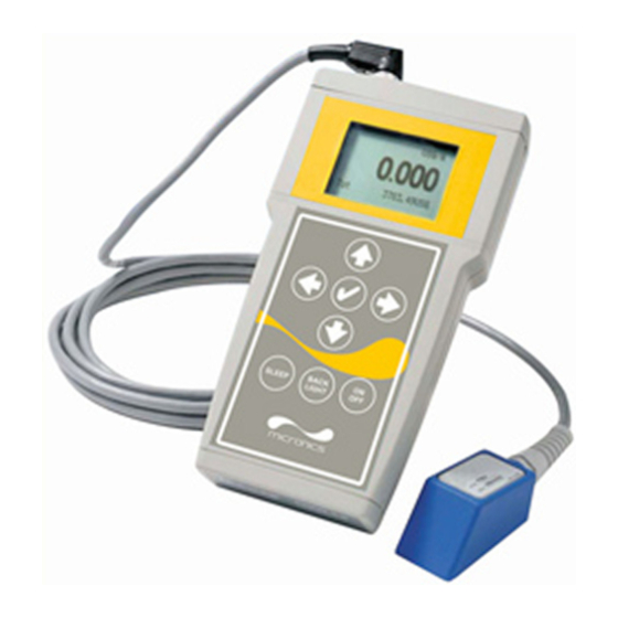
- Page 1 USER'S GUIDE Installation & Operation Instructions Portable Doppler Flow Meter Model PF D550 Manual Series A.1.2...
- Page 2 Note: This page has been left blank intentionally.
-
Page 3: Table Of Contents
PF D550 Non-Contacting Doppler Flow Meter INDEX Battery............4 Connections . -
Page 4: Battery
4-20mA Active only when powered by AC charger, maximum load 500 ohm. Cable Part #USB-PD is supplied for connecting the PF D550 to a PC or laptop. POWER An AC powered 15 volt DC power module is supplied for battery charging and continuous use. -
Page 5: Keypad System
PF D550 Non-Contacting Doppler Flow Meter KEYPAD SYSTEM The following diagram shows the PF D550 menu system. Arrows show the four directions to leave a menu box. Pressing a corresponding keypad arrow will move to the next item in the direction shown. -
Page 6: Calibration Menu
PF D550 Non-Contacting Doppler Flow Meter CALIBRATION MENU Page 6... -
Page 7: Message
USG/m 0.000 The main display shows the units selected from the Units/Mode menu, Flow or Velocity rate being measured, TOTALIZER. The PF D550 will start-up with this display and will return to this screen after a timeout if 20130.8USG keys are not pressed in other menus. -
Page 8: Password
PF D550 Non-Contacting Doppler Flow Meter 24 HR LOG --24 hr log---------- Mar. 24/2010 >Date Total 135470.0USG Press from the RUN display to view a formatted flow report from Average 1125.3USG/m Maximum 2725.0USG/m instruments with a built-in data logger. Press... -
Page 9: Units/Mode
PF D550 Non-Contacting Doppler Flow Meter UNITS/MODE --Units/Mode-------- >Mode Flow Linear From press the and then the to select >Mode Flow Volume . Flow mode displays the flow rate in engineering units (e.g. Velocity Time gpm, litres/sec, etc.) Press the... -
Page 10: Calibration
PF D550 Non-Contacting Doppler Flow Meter CALIBRATION --Calibration------- >20mA at 2500.0USG/m 4mA at 0.000USG/m Press the to enter. Use to position >Calibration Pipe ID 12.00in Damping before each menu item and to enter. When settings are completed > press to store and return to the Calibration menu... -
Page 11: Data Logging
The current log file will be erased from memory and a new log file will start. RETRIEVE LOG FILE Install Micronics Logger on your PC or laptop. Refer to the Help menu in the program for detailed instructions. - Connect the to the PC using the supplied USB cable. -
Page 12: Special Functions
PF D550 Non-Contacting Doppler Flow Meter SPECIAL FUNCTIONS --Special Functions- >Language English Reset Totalizer Select Language English French Spanish Negative Totals Reverse Flow Cal Constant 1.000 Restore Defaults Press and select to erase and restart the Reset Totalizer New Password 0000 totalizer at zero. - Page 13 PF D550 Non-Contacting Doppler Flow Meter SIMULATION --Simulation-------- >Flow 0.000USG/m 4-20mA 4.00mA Exercises the 4-20mA output and digital display (does not affect the totalizer). Press and then to change the simulated output. Press Output to begin simulation. The 4-20mA output and relay states will be displayed on the screen.
- Page 14 Before permanently mounting a Doppler sensor onsite testing is recommended to determine optimum mounting position. Use the sensor coupling compound (supplied with each Micronics flow meter, or petroleum gel, acoustic compound or electrocardiograph gel). Take several readings around the axis of the pipe and then at several points upstream and downstream from the selected position, checking for consistent readings.
-
Page 15: Sensor Mounting
The objective of site preparation is to eliminate any discontinuity between the sensor and the pipe wall, which would prevent acoustical coupling. A PC4 Sensor Mounting Kit is supplied with each Micronics flow meter. It includes recommended coupling compound in a plastic applicator and a stainless steel mounting bracket with adjustable pipe straps. - Page 16 Additional supply: order Micronics Option CC b) High Temperature compound (supplied with Sensor Option SE3H) Additional supply: order Micronics Option AP-1W c) Water-based sonic compound: Order Micronics Option CC30 d) Electrocardiograph gel e) Petroleum gel (Vaseline) The above are arranged in their order of preferred application.
- Page 17 PF D550 Non-Contacting Doppler Flow Meter SENSOR MOUNTING/COUPLING RECOMMENDATIONS GOOD Page 17...
-
Page 18: Troubleshooting
PF D550 Non-Contacting Doppler Flow Meter FIELD TROUBLESHOOTING Possible Causes: Corrective Action: METER READING LOWER THAN EXPECTED Calibration Error • Review menu and UNITS/MODE Pipe ID Lower flow rate than expected • Investigate pump/valves. Compare velocity with alternate instrument Signal not penetrating far enough into the flow •... - Page 19 PF D550 Non-Contacting Doppler Flow Meter Possible Causes: Corrective Action: Coupling compound washed out, or sensor loose • Remount sensor on pipe • Use Dow Corning Silicone #4 METER READING TOO HIGH Calibration error • Review menu and Pipe UNITS/MODE Vibration or noise on the pipeline •...
-
Page 20: Common Questions And Answers
COMMON QUESTIONS AND ANSWERS The pipe vibrates. Will it affect the flow meter? Common vibration frequencies are far lower than the sonic frequencies used by the Micronics flow meter, and will not normally affect accuracy or performance. However, applications where very weak Doppler signal is present (when sensitivity is adjusted to maximum and signal strength is low), accuracy may be affected by pipe vibration, or the flow meter may show readings under no-flow conditions. - Page 21 The solid state sensor has no moving parts to wear PF D550 and affect calibration. The Doppler flow technique generates an ultrasonic signal proportional to the velocity of flow. All Micronics timing/counting circuits use crystal-controlled frequency references to eliminate any drift in the processing circuitry. Page 21...
-
Page 22: Product Return Procedure
PF D550 Non-Contacting Doppler Flow Meter PRODUCT RETURN PROCEDURE Instruments may be returned to for service or warranty repair. Micronics Obtain an RMA Number from Micronics - Before shipping a product to the factory please contact Micronics by telephone, fax or email to obtain an RMA number (Returned Merchandise Authorization). -
Page 23: Flow Meter Data Sheet
PF D550 Non-Contacting Doppler Flow Meter FLOW METER DATA SHEET Micronics Please complete and return this form to Micronics. It is important. We use this information to check our database Knaves Beech Business Centre, for performance of Micronics flow meters in similar... -
Page 24: Warranty
PF D550 Non-Contacting Doppler Flow Meter LIMITED WARRANTY _____________________ Micronics warrants, to the original purchaser, its products to be free from defects in material and workmanship for a period of one year from date of invoice. will replace Micronics repair, free of charge, any... -
Page 25: Specifications
PF D550 Non-Contacting Doppler Flow Meter SPECIFICATIONS 4.33” 1.6” Flow Rate Range: ± 0.03 to 12.2 m/sec (± 0.1 to 40 110 mm 41 mm ft/sec) in most applications Pipe Size: Ultrasonic Sensor mounts on any pipe from 12.5 mm to 4.5m ID (1/2" to 180") - Page 26 PF D550 Non-Contacting Doppler Flow Meter PSE4 Doppler Sensor Minimum Pipe Diameter: 12.5mm (0.5") ID, 15mm (0.6") OD Maximum Pipe Diameter: 4.5 m (180") ID Operating Temperature: -40° to 93°C (-40° to 200°F) Operating Frequency: 640 KHz Sensor Housing: Stainless Steel Sensor Cable: 3.66 m (12 ft.) shielded coaxial pair...
-
Page 27: Appendix A - Conversion Table
PF D550 Non-Contacting Doppler Flow Meter APPENDIX A - CONVERSION TABLE CONVERSION GUIDE FROM MULTIPLY BY US GALLONS CUBIC FEET 0.1337 US GALLONS IMPERIAL GALS 0.8327 US GALLONS LITRES 3.785 US GALLONS CUBIC METERS 0.003785 LITRES/SEC 15.85 LITRES CUBIC METERS 0.001... -
Page 28: Pipe Charts
PF D550 Non-Contacting Doppler Flow Meter PIPE CHARTS Carbon Steel & PVC Pipe Standard Extra Heavy Dbl. Extra Pipe Pipe Schedule 40 Schedule 80 Heavy Schedule 10 Schedule 20 Schedule 30 Schedule 40 Size O.D. I.D. WALL I.D. WALL I.D. - Page 29 PF D550 Non-Contacting Doppler Flow Meter Stainless Steel, Hastelloy "C" & Titanium Pipe Pipe Pipe Schedule 5 S (a) Schedule 10 S (a) Schedule 40 S Schedule 80 S Size O.D. I.D. WALL I.D. WALL I.D. WALL I.D. WALL ½...
- Page 30 PF D550 Non-Contacting Doppler Flow Meter Cast Iron Pipe - ASA Standard Pipe Pipe Class Class Class Class Class Class Class Size O.D. WALL I.D. WALL I.D. WALL I.D. WALL I.D. WALL I.D. WALL I.D. WALL I.D. 3.96 0.32 3.32 0.32...
Need help?
Do you have a question about the PF D550 and is the answer not in the manual?
Questions and answers