Table of Contents
Advertisement
Quick Links
Portaflow 222 and 333
Portaflow 222: Portable Ultrasonic Flow Meter
Portaflow 333: Portable Ultrasonic Heat Meter
User Manual
Portaflow 333 shown
Micronics Ltd, Knaves Beech Business Centre,
Davies Way, Loudwater, High Wycombe, Bucks HP10 9QR
Telephone: +44(0)1628 810456
E-mail:
sales@micronicsltd.co.uk
www.micronicsflowmeters.com
Issue 3.1
Advertisement
Table of Contents
Troubleshooting

Subscribe to Our Youtube Channel
Related Manuals for Micronics Portaflow 222


Summary of Contents for Micronics Portaflow 222
- Page 1 Portaflow 222 and 333 Portaflow 222: Portable Ultrasonic Flow Meter Portaflow 333: Portable Ultrasonic Heat Meter User Manual Portaflow 333 shown Micronics Ltd, Knaves Beech Business Centre, Davies Way, Loudwater, High Wycombe, Bucks HP10 9QR Telephone: +44(0)1628 810456 E-mail: sales@micronicsltd.co.uk www.micronicsflowmeters.com...
-
Page 3: Table Of Contents
Micronics Portaflow 222 & 333 User Manual CONTENTS 1 INTRODUCTION ........................1 General Description ......................1 How Does It Work? ......................2 Package Contents ......................3 Optional equipment (333 models only) ................5 Display and connectors ...................... 6 Keypad ..........................7 1.6.1... - Page 4 Portaflow 222 & 333 User Manual Micronics 4.6.1 Adjusting the zero cutoff .................... 27 4.6.2 Adjusting the zero flow offset ..................27 4.6.3 Adjusting the calibration factor ................... 28 4.6.4 Adjusting the roughness factor .................. 29 4.6.5 Adjusting the damping factor ..................30 5 LOGGING FUNCTIONS .......................
-
Page 5: Introduction
Micronics Portaflow 222 & 333 User Manual INTRODUCTION General Description The Portaflow range of portable flow meters uses clamp-on transducers to enable the flow of a liquid within a closed pipe to be measured accurately without needing to insert any mechanical parts through the pipe wall or protrude into the flow system. -
Page 6: How Does It Work
Portaflow 222 & 333 User Manual Micronics How Does It Work? Portaflow flow meters use a cross correlation transit time algorithm to provide accurate flow measurements. An ultrasonic beam of a given frequency is generated by applying a repetitive voltage pulse to the transducer crystals. -
Page 7: Package Contents
Micronics Portaflow 222 & 333 User Manual Package Contents The unit consists of the following components: Portaflow unit Incorporating keypad and backlit display (333 model shown, 222 unit has white case). Power supply with UK/US/European adapters, 110/240VAC. Signal cable (4-20mA & 3 digital outputs) Transducer cables (x2), 2m. - Page 8 Portaflow 222 & 333 User Manual Micronics All models 333 units only Figure 2 Package Contents (333 model shown) Page 4 Issue 3.1 Feb 20...
-
Page 9: Optional Equipment (333 Models Only)
Micronics Portaflow 222 & 333 User Manual Optional equipment (333 models only) Transducer set 'D' – used for monitoring pipes of 1500mm to 5000mm diameter, over a temperature range -20°C to +80°C. Kit is supplied in a separate case and includes the sensors together with ratchet straps and guide rails for attaching to the pipe. -
Page 10: Display And Connectors
Portaflow 222 & 333 User Manual Micronics Display and connectors The Portaflow unit is microprocessor-controlled, operated through a menu system using an inbuilt LCD display and keypad. It can display the instantaneous fluid flow rate or velocity, together with totalised values. -
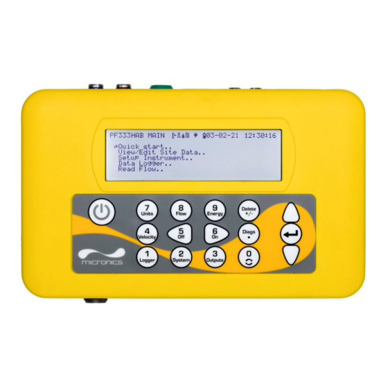
Page 11: Keypad
Micronics Portaflow 222 & 333 User Manual Keypad The instrument is configured and controlled via a 16-key tactile membrane keypad, as shown in Figure x. ON/OFF Numerical keypad with Scroll up dual function keys ENTER (SELECT) Scroll down Figure 5 Portaflow keypad 1.6.1... -
Page 12: Menus And The Menu Selection Keys
Portaflow 222 & 333 User Manual Micronics models only) 333 models only: switch to the Read Energy display from the Read Velocity display or Read Flow display Delete No shortcut function: within text entries, deletes character to left of flashing cursor. -
Page 13: Installation
Micronics Portaflow 222 & 333 User Manual INSTALLATION Positioning the Transducers For accurate measurements, the transducers must be installed at a position where the fluid flows uniformly. Flow profile distortions can result from upstream disturbance such as bends, tees, valves, pumps and other similar obstructions. -
Page 14: Attaching The Transducers
IMPORTANT: DO NOT EXPECT TO OBTAIN ACCURATE RESULTS IF THE UNIT IS POSITIONED CLOSE TO ANY OBSTRUCTION THAT DISTORTS THE UNIFORMITY OF THE FLOW PROFILE. MICRONICS LTD ACCEPTS NO RESPONSIBILITY OR LIABILITY IF PRODUCT HAS NOT BEEN INSTALLED IN ACCORDANCE WITH THESE INSTRUCTIONS. -
Page 15: Fitting The Transducers
Micronics Portaflow 222 & 333 User Manual THE EFFECTIVE LENGTH OF THE CHAIN WRAPPED AROUND THE PIPE BY CONNECTING THE TENSIONING BAR TO THE NEXT LINK IN THE CHAIN, THEN RE-TENSION. Tensioning thumbwheel Tension bar Separation bar screw Separation bar... - Page 16 Portaflow 222 & 333 User Manual Micronics Connect the transducers to the Portaflow unit using the coaxial cables provided. The RED cable must be connected to the upstream transducer and the BLUE cable to the downstream transducer. The sockets are also colour-coded.
-
Page 17: Connecting Temperature Probes (Portaflow 333 Only)
Micronics Portaflow 222 & 333 User Manual Connecting Temperature Probes (Portaflow 333 only) The temperature sensors must be located at the input and output of the system that is being monitored. The area of pipe where they are to be attached must be free of grease and any insulating material. - Page 18 Portaflow 222 & 333 User Manual Micronics Two separate 4-core plug-in cables are provided for the Temperature Sensor Probes connections. 333 Temperature Probe Wiring COLD White White White Solder pin side White Output Figure 12 Portaflow 333 Temperature Probe Wiring Page 14 Issue 3.1 Feb 20...
-
Page 19: Connecting Outputs
Micronics Portaflow 222 & 333 User Manual Connecting Outputs The output cable provides a 4-20mA current source that can drive a maximum load of 620Ω and 3 digital output pairs for pulse or alarm outputs. The isolated pulse output is provided by a SPNO/SPNC MOSFET relay which has a maximum load current of 500mA and maximum load voltage of 24V AC/DC. -
Page 20: 2.5 Connecting The Power Supply
Portaflow 222 & 333 User Manual Micronics 2.5 Connecting the Power Supply Operating power is provided by an internal battery that can be charged from the utility supply using the supplied external charger. When you first receive the unit you must put the battery on charge for a minimum of 6.5hrs before use. -
Page 21: Switching On For The First Time
Micronics Portaflow 222 & 333 User Manual Switching on for the first time Leave the instrument on charge for at least 6.5 hours before using it for the first time. Switch on the instrument by pressing and holding down the ON/OFF button for about 5 seconds. -
Page 22: Enabling/Disabling The Backlight
Portaflow 222 & 333 User Manual Micronics Use the UP/DOWN arrow keys to choose the required format: DD-MM-YY or MM-DD-YY. Press the ENTER key. Use the UP/DOWN arrow keys to select Set Date & Time. Press ENTER. A flashing cursor appears under the first date number. -
Page 23: Using The Quick Start Menu
Micronics Portaflow 222 & 333 User Manual USING THE QUICK START MENU If you want to perform a ‘one-off’ flow reading at a particular pipe location the Quick start menu provides the quickest way to set up the Portaflow system and access the FLOW READING screen. - Page 24 Portaflow 222 & 333 User Manual Micronics Identify the pipe lining material from the Pipe Lining DD-MM-YY HH:MM:SS following options: ->Lining material Glass Continue.. None/Rubber/Glass/Epoxy/Concrete/ Main Menu.. Other (m/s). If the material is not listed, select Other (m/s) and enter the propagation rate of...
-
Page 25: Attaching And Connecting The Sensors
Micronics Portaflow 222 & 333 User Manual 11. If you prefer to use a different configuration, Sensors DD-MM-YY HH:MM:SS press the UP or DOWN arrow key to select a ->Sensor Set A-ST different sensor set and mode. Sensor Mode Reflex Return to Summary Screen.. -
Page 26: Total Flows
Portaflow 222 & 333 User Manual Micronics Total flows The basic measurement indicated on the READ FLOW screen is the instantaneous flow rate, which in some applications may vary over a period of time. Average flow rates are therefore often required in order to get a better understanding of an application’s true performance. -
Page 27: Managing Named Sites
Micronics Portaflow 222 & 333 User Manual MANAGING NAMED SITES Setting up the Portaflow system using the Quick Start method described in the previous chapter is the recommended method to use in a ‘one-off’ situation. If you have several site locations that you want to monitor on a frequent basis it is better to set up a named ‘Site’... -
Page 28: Selecting An Existing Site
Portaflow 222 & 333 User Manual Micronics Selecting an existing site View/Edit Sit DD-MM-YY HH:MM:SS ->Choose from list of sites.. Select View / Edit Site Data from the MAIN Add new site.. MENU. Site name.. Site01 Pipe outside diameter 114.30 Select Choose from list of sites. -
Page 29: Adding A New Site
Micronics Portaflow 222 & 333 User Manual Adding a new site NOTE: ONCE YOU HAVE SET UP A NAMED SITE YOU ARE ADVISED TO LOG SOME DATA TO THE SITE IN ORDER TO AVOID THE POSSIBILITY OF THE SITE NAME BEING OVERWRITTEN WHEN THE QUICK START DATA IS SAVED. -
Page 30: Editing Site Data
Portaflow 222 & 333 User Manual Micronics Editing site data View/Edit Sit DD-MM-YY HH:MM:SS Having selected the appropriate site (see page ->Choose from list of sites.. Add new site.. 24), scroll through the menu list and Site name.. enter/change the pipe, sensor and fluid Pipe outside diameter 114.30... -
Page 31: Changing Calibration Parameters
Micronics Portaflow 222 & 333 User Manual Changing calibration parameters The Portaflow is fully calibrated before it leaves the factory; however the following adjustments are provided to allow you to further ‘fine tune’ your instrument to suit local conditions and application where necessary. -
Page 32: Adjusting The Calibration Factor
Portaflow 222 & 333 User Manual Micronics NOTE: IN ORDER TO CANCEL ANY APPLIED OFFSET YOU MUST EITHER READ FLOW VIA QUICK START OR SWITCH THE PORTAFLOW UNIT OFF & ON. ANY VALUE THAT YOU TRIM- OUT USING THE OFFSET ADJUSTMENT WILL BE ADDED/SUBTRACTED FROM THE FLOW READING ACROSS THE WHOLE RANGE. -
Page 33: Adjusting The Roughness Factor
Micronics Portaflow 222 & 333 User Manual 4.6.4 Adjusting the roughness factor The roughness factor compensates for the condition of the internal pipe wall, as a rough surface will cause turbulence and affects the flow profile of the liquid. In most situations, it is not possible to inspect the pipe internally and the true condition is not known. -
Page 34: Adjusting The Damping Factor
Portaflow 222 & 333 User Manual Micronics 4.6.5 Adjusting the damping factor By averaging-out the flow rate over several seconds, the Damping factor can be used to smooth out rapid changes in flow rate to prevent wild fluctuations in the displayed flow value. It has a range of 0 - 50 s, with a default setting of 10s. -
Page 35: Logging Functions
Micronics Portaflow 222 & 333 User Manual LOGGING FUNCTIONS NOTE: THIS CHAPTER ONLY APPLIES TO 333 MODELS. 222 MODELS DO NOT HAVE LOGGING CAPABILITIES. This procedure shows you how to set up a basic logging session under manual start/stop control. -
Page 36: File Naming
Portaflow 222 & 333 User Manual Micronics Duration shows the logging period calculated from the Start and Stop times. Select Save Setup & Exit and press the ENTER key to return to the Real Time Logger screen. File naming If you choose to save the existing log it will be saved to the highest number site that does not currently have an attached log (e.g. -
Page 37: Clearing Log Files
Micronics Portaflow 222 & 333 User Manual Logged data for the selected site is now copied to the USB memory stick. Upon completion select Exit to return to the MAIN menu. Clearing Log Files Access the MAIN menu. IMPORTANT: IF THIS IS DONE FROM THE FLOW READING SCREEN ANY LOGGING CURRENTLY TAKING PLACE WILL BE TERMINATED. -
Page 38: Outputs
Portaflow 222 & 333 User Manual Micronics OUTPUTS 4-20mA Current Output The default 4-20mA output setting is OFF, and the 4-20mA LED on the keypad will not be illuminated. The default flow for 4mA is 0. If the flow reading is greater than that set as the 20mA value, or there is negative flow, or no flow signal can be detected, then an alarm current of 2.5mA. -
Page 39: Converting The Measured Current To Flow Rate
Micronics Portaflow 222 & 333 User Manual 6.1.1 Converting the measured current to flow rate is ‘0’ (l/min), as shown Assume the maximum flow rate is F (l/min) and the minimum flow rate F below. To calculate the flow rate (l/min) for a measured current (mA) then: ��������... -
Page 40: Setting Up Volumetric Pulse
Portaflow 222 & 333 User Manual Micronics Use the UP/DOWN arrow keys to select Digital Device 1/2/3 Setup. Press the ENTER key. The Output 1/2/3 menu is displayed. Use the UP/DOWN arrow keys to select Function. Press the ENTER key. -
Page 41: Frequency Mode
Micronics Portaflow 222 & 333 User Manual Formula to obtain Volume per Pulse based on a (default) 50ms pulse width: Volume per Pulse >= maximum flow rate (in litres per minute) / 600 Example for maximum flow rate of 500 l/min: Volume per Pulse >= 500 l/min / 600 = 0.833 litres per pulse... -
Page 42: Maintenance And Repair
The instrument and sensors should be calibrated at least once every 12 months. Contact Micronics or your local service agent for details. 10. When returning product to Micronics make sure it is clean and please notify Micronics if the instrument has been in contact with any hazardous substances. -
Page 43: Troubleshooting
Micronics Portaflow 222 & 333 User Manual TROUBLESHOOTING Overview If you have a problem with your flow monitoring system it can be due to any of the following: Faulty If you suspect the instrument is faulty you can check it out using a test block as described on page 44. -
Page 44: General Troubleshooting Procedure
Portaflow 222 & 333 User Manual Micronics General Troubleshooting Procedure Figure 14 Troubleshooting chart Page 40 Issue 3.1 Feb 20... -
Page 45: Warning And Status Messages
Micronics Portaflow 222 & 333 User Manual Warning and Status Messages 8.3.1 Flow Rate Errors No flow signal Interpretation: This message appears when the transducers cannot send or receive signals to each other. Response: Firstly check that all cables are connected, transducers are on the pipe correctly with sufficient couplant on the face. -
Page 46: Data Logging Errors
Portaflow 222 & 333 User Manual Micronics Calibration 20mA Error! NOTE: THE 4-20MA OUTPUT IS CALIBRATED BEFORE THE INSTRUMENT LEAVES THE FACTORY AND SHOULD NOT REQUIRE FURTHER ADJUSTMENT. Interpretation: You have adjusted the DAC outside its accepted range when calibrating the 20mA signal output. - Page 47 Micronics Portaflow 222 & 333 User Manual Response: Enter a valid number. Wall thickness out of range Interpretation: You have entered an out-of-range value for the pipe wall thickness dimension – accepted range is 1mm - 75mm. Response: Enter a valid number.
-
Page 48: Test Block
Portaflow 222 & 333 User Manual Micronics Test Block A test block is included with the Portaflow equipment to allow the transducers and inter-connecting cables to be functionally checked. Switch ON the instrument. Select Quick Start and enter the parameters shown in the table below for the appropriate... -
Page 49: Reset
Micronics Portaflow 222 & 333 User Manual 16. The signal strength indicator at the left of the display should show 3–4 bars. Figure 15 Sensors on the test block Reset To reset the Portaflow, carefully inserting a straightened paperclip into the pinhole located in the right-hand side of the instrument to operate the internal reset switch. -
Page 50: Diagnostics
Portaflow 222 & 333 User Manual Micronics Diagnostics This feature is designed for advanced users and is intended to provide information that will aid the user to diagnose problems – e.g. no signal strength. When operating in the FLOW READING mode you can access a diagnostics screen by pressing the Daigs function key and then selecting Diagnostics from the FLOW READING OPTIONS screen. - Page 51 Micronics Portaflow 222 & 333 User Manual Issue 3.1 Feb 20 Page 47...
-
Page 52: Appendix
Portaflow 222 & 333 User Manual Micronics APPENDIX Specification General DSP Measurement Technique Transit time Timing Resolution 50 pico-second, continuous signal level indication on display Flow Velocity Range Minimum Velocity 0.1m/s; Max Velocity 20m/s: Bi-directional. Turn Down Ratio 100:1 Accuracy ±0.5% to ±2% of flow reading for flow rate >0.2m/s... - Page 53 Micronics Portaflow 222 & 333 User Manual Data Logged Log application details, flow rate. Logs data selected in setup, e.g l, gals, USgals, m³. No. Data Points 200K Time Stamping All data points No. Sites No. Datapoints per Site All free memory can be allocated to any site up to a max of 200,000 data points 5 secs to 1hr –...
- Page 54 BS EN 61326 - 1:2006, BS EN 61326-2-3:2006 Battery Charger EN61204 - 3 Shipping Information Box Dimensions 410mm x 205mm x 355mm Weight 7.5 kg Volumetric Weight 5 kg Micronics reserve the right to alter any specification without notification. Page 50 Issue 3.1 Feb 20...
-
Page 55: Default Values
Micronics Portaflow 222 & 333 User Manual Default values The settings will be configured at the factory for metric units. The following table lists the metric and imperial default values. Parameter Default Value Metric Imperial Dimensions inches Flow Units l/min... -
Page 56: Declaration Of Conformity
Portaflow 222 & 333 User Manual Micronics DECLARATION OF CONFORMITY Page 52 Issue 3.1 Feb 20...
Need help?
Do you have a question about the Portaflow 222 and is the answer not in the manual?
Questions and answers