Table of Contents
Advertisement
Quick Links
Portaflow 222 and 333
Portaflow 222: Portable Ultrasonic Flow Meter
Portaflow 333: Portable Ultrasonic Heat Meter
User Manual
Portaflow 333 shown
Micronics Ltd, Knaves Beech Business Centre,
Davies Way, Loudwater, High Wycombe, Bucks HP10 9QR
Telephone: +44(0)1628 810456
E-mail:
sales@micronicsltd.co.uk
www.micronicsflowmeters.com
Issue 1.0
Advertisement
Table of Contents
Troubleshooting

Related Manuals for Micronics Portaflow 222


Summary of Contents for Micronics Portaflow 222
- Page 1 Portaflow 222 and 333 Portaflow 222: Portable Ultrasonic Flow Meter Portaflow 333: Portable Ultrasonic Heat Meter User Manual Portaflow 333 shown Micronics Ltd, Knaves Beech Business Centre, Davies Way, Loudwater, High Wycombe, Bucks HP10 9QR Telephone: +44(0)1628 810456 E-mail: sales@micronicsltd.co.uk www.micronicsflowmeters.com...
-
Page 3: Table Of Contents
Micronics Portaflow 222 & 333 User Manual CONTENTS 1 INTRODUCTION ........................1 General Description ......................1 How Does It Work? ......................2 1.2.1 Reflex (V) Mode ......................4 1.2.2 Double Reflex (W) Mode ..................... 4 1.2.3 Triple Reflex (WV) Mode ..................... 4 1.2.4... - Page 4 Portaflow 222 & 333 User Manual Micronics 4 MANAGING NAMED SITES ....................30 View/Edit Site Data ......................30 Selecting an Existing Site ....................31 Adding a New Site ......................32 Changing a Site Name ...................... 32 Editing Site Data ....................... 33 Changing Calibration Parameters ..................
- Page 5 Micronics Portaflow 222 & 333 User Manual 11.3.3 Current Loop and Digital Output Errors & Messages ..........60 11.3.4 Data Logging Errors & Messages ................61 11.3.5 Battery Errors & Messages ..................63 11.3.6 Set-up and Other Errors & Messages ................ 63 11.4 Test Block .........................
-
Page 7: Introduction
Micronics Portaflow 222 & 333 User Manual INTRODUCTION General Description The Portaflow range of portable flow meters uses clamp-on transducers to enable the flow of a liquid within a closed pipe to be measured accurately without needing to insert any mechanical parts through the pipe wall or protrude into the flow system. -
Page 8: How Does It Work
Portaflow 222 & 333 User Manual Micronics Typical applications: • River water • Seawater • Potable water • Demineralised water • Treated water How Does It Work? Portaflow flow meters use a cross correlation transit time algorithm to provide accurate flow measurements. - Page 9 Micronics Portaflow 222 & 333 User Manual Reflex (V) Mode (single bounce) Reflex (W) Mode (double bounce) Reflex (WV) Mode (triple bounce) Reflex (WW) Mode (quadruple bounce) Diagonal Mode Figure 2 Operating modes Issue 1.0 March 2021 Page 3...
-
Page 10: Reflex (V) Mode
Portaflow 222 & 333 User Manual Micronics 1.2.1 Reflex (V) Mode This is the mode most commonly used. The two transducers (U & D) are attached to the pipe in line with each other and the signals passing between them are reflected by the opposite pipe wall. -
Page 11: Package Contents
Micronics Portaflow 222 & 333 User Manual Package Contents The unit consists of the following components: Portaflow unit Incorporating keypad and backlit display (PF333 model shown, PF222 unit has light-grey case). Power supply with UK/US/European adapters, 110/240VAC Output signal cable (current loop & 3 digital outputs) Transducer cables x 2, (2m) Chains x 2 (3.3m) - Page 12 Portaflow 222 & 333 User Manual Micronics All models | PF333 units only Figure 3 Package Contents (PF333 model shown) Page 6 Issue 1.0 March 2021...
-
Page 13: Optional Equipment (Pf333 Models Only)
Micronics Portaflow 222 & 333 User Manual Optional Equipment (PF333 Models Only) A magnetic guide rail kit is available, as an optional extra, for use on mild steel and cast iron pipes (see Figure 4). Figure 4 Magnetic guide rail Issue 1.0 March 2021... -
Page 14: Display And Connectors
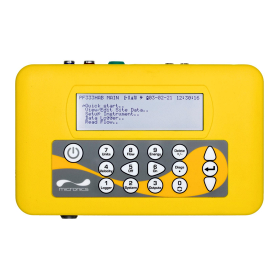
Portaflow 222 & 333 User Manual Micronics Display and Connectors The Portaflow unit is microprocessor-controlled, operated through a menu system using an inbuilt LCD display and keypad. It can display the instantaneous fluid flow rate or velocity, together with totalised values. - Page 15 Micronics Portaflow 222 & 333 User Manual Portaflow 333 units can also act as a data logger. When operating in the data logger mode, data is saved to non-volatile internal storage. This data may be downloaded at a later date via a flash drive inserted in the USB socket.
-
Page 16: Keypad
Portaflow 222 & 333 User Manual Micronics Keypad The instrument is configured and controlled via a 16-key tactile membrane keypad, as shown in Figure 5. ON/OFF Numerical keypad with Scroll up dual function keys ENTER (SELECT) Scroll down Figure 6 Portaflow keypad 1.6.1... -
Page 17: Menus And The Menu Selection Keys
Micronics Portaflow 222 & 333 User Manual Switch to the Read Velocity display from the Read Flow display or Read Energy display (PF333 models only) No function - reserved for future use No function - reserved for future use Cycle through the available display units... - Page 18 Portaflow 222 & 333 User Manual Micronics Some menus have more options than can be shown on the screen at the same time, in which case the ‘overflowed’ choices can be brought into view by continuing to scroll beyond the lowest visible item.
-
Page 19: Installation
Micronics Portaflow 222 & 333 User Manual INSTALLATION Positioning the Transducers For accurate measurements, the transducers must be installed at a position where the fluid flows uniformly. Flow profile distortions can result from upstream disturbance such as bends, tees, valves, pumps and other similar obstructions. -
Page 20: Attaching The Transducers
IMPORTANT: DO NOT EXPECT TO OBTAIN ACCURATE RESULTS IF THE UNIT IS POSITIONED CLOSE TO ANY OBSTRUCTION THAT DISTORTS THE UNIFORMITY OF THE FLOW PROFILE. MICRONICS LTD ACCEPTS NO RESPONSIBILITY OR LIABILITY IF PRODUCT HAS NOT BEEN INSTALLED IN ACCORDANCE WITH THESE INSTRUCTIONS. -
Page 21: Fitting The Transducers
Micronics Portaflow 222 & 333 User Manual Rotate the complete guide rail assembly so that it is approximately 45° with respect to the top of the pipe. Then tighten the chain by turning the tensioning thumb-wheel on each guide block until the assembly is securely attached to the pipe. -
Page 22: Fixing Transducers In Diagonal Mode
Portaflow 222 & 333 User Manual Micronics Slide the transducer cover plate over the top of the transducer and tighten the thumbscrew finger-tight to secure the transducer in place. When securing the cover plate take care to leave sufficient room around the transducer connector to connect the cable. - Page 23 Micronics Portaflow 222 & 333 User Manual At this point, draw another line around the circumference of the pipe. Mark the position 180° from the upstream transducer’s position. This is the location for the downstream transducer. Upstream transducer Separation distance...
-
Page 24: Connecting Temperature Probes (Pf333 Models Only)
Portaflow 222 & 333 User Manual Micronics Connecting Temperature Probes (PF333 Models Only) The temperature sensors must be located at the flow and return of the system that is being monitored. The area of pipe where they are to be attached must be free of grease and any insulating material. - Page 25 Micronics Portaflow 222 & 333 User Manual The sockets on the Electronics Module are marked Red (Hot) and Blue (Cold) – see Figure 5 and Figure 14. This defines the location of the temperature sensors on installations where heat is being extracted from the system.
-
Page 26: Connecting Outputs
Portaflow 222 & 333 User Manual Micronics Connecting Outputs The output cable provides a current source that can drive a maximum load of < 600Ω and 3 digital output pairs for pulse, frequency or alarm outputs. The isolated pulse output is provided by a SPNO/SPNC MOSFET relay which has a maximum load current of 500mA and maximum load voltage of 24V AC/DC. -
Page 27: 2.5 Connecting The Power Supply
Micronics Portaflow 222 & 333 User Manual 2.5 Connecting the Power Supply Operating power is provided by an internal battery that can be charged from the utility supply using the supplied external charger. When you first receive the unit, you should charge the battery for a minimum of 15 minutes before use. -
Page 28: Switching On For The First Time
Portaflow 222 & 333 User Manual Micronics Switching on for the First Time Leave the instrument on charge for at least 15 minutes before using it for the first time. Switch on the instrument by pressing and holding down the ON/OFF button for about 2 to 3 seconds. -
Page 29: Setting The Date & Time
Micronics Portaflow 222 & 333 User Manual 2.6.3 Setting the Date & Time System Settings DD-MM-YY H:MM:SS From the MAIN menu, use the Up and Down scroll keys to select Setup Instrument. Press Lock-screen Timeout Back-light mode the ENTER Key. With System selected in the Back-light Timeout Options menu, press the ENTER Key. -
Page 30: Enabling/Disabling Audible Keypress
Portaflow 222 & 333 User Manual Micronics With the chosen mode selected, press the ENTER key. If you select TIMED, use the UP/DOWN arrow keys to select to Back-light Timeout. Press the ENTER key. Use the keypad to enter the required timeout interval (5-120s). Press the ENTER key. -
Page 31: Using The Quick Start Menu
Micronics Portaflow 222 & 333 User Manual USING THE QUICK START MENU If you want to perform a ‘one-off’ flow reading at a particular pipe location the Quick start wizard provides the simplest way to set up the Portaflow system and access the FLOW READING screen. - Page 32 Portaflow 222 & 333 User Manual Micronics Identify the pipe lining material from the Pipe Lining DD-MM-YY HH:MM:SS following options: ↱Lining material Glass None/Rubber/Glass/Epoxy/Concrete/ Continue.. Main Menu.. Other (m/s). If the material is not listed, select Other (m/s) and enter the propagation rate of the pipe wall material in metres/sec.
-
Page 33: Attaching And Connecting The Flow Sensors
Micronics Portaflow 222 & 333 User Manual 10. The Summary screen is displayed. This displays Summary DD-MM-YY HH:MM:SS a summary of the entered parameters and Site: QuickStart informs you of the type of sensor to be used, the Sensor separation: 69.9mm mode of operation and the distance to set up Pipe OD: 114.3mm, ID 98.3mm... -
Page 34: Flow / Energy / Velocity Monitoring
Portaflow 222 & 333 User Manual Micronics If the flow reading exceeds a value of +/-99999 in the selected units then the display will change to exponential (or scientific) notation. This is used in Microsoft™ Excel™ and many other software packages. -
Page 35: Calculating The Average Flow Or Power
Micronics Portaflow 222 & 333 User Manual 3.5.1 Calculating the Average Flow or Power To calculate the average flow, wait for the allotted monitoring period to expire then divide the indicated total volume or energy by the time taken. This will give you the average flow in m/s, gals/hour or whatever units you select. -
Page 36: Managing Named Sites
Portaflow 222 & 333 User Manual Micronics MANAGING NAMED SITES Setting up the Portaflow system using the Quick Start method described in the previous chapter is the recommended method to use in a ‘one-off’ situation. If you have several site locations that you want to monitor on a frequent basis it is better to set up a named ‘Site’... -
Page 37: Selecting An Existing Site
Micronics Portaflow 222 & 333 User Manual Selecting an Existing Site View/Edit Sit DD-MM-YY HH:MM:SS ↱Choose from list of sites.. Select View / Edit Site Data from the MAIN Add new site.. MENU. Site name.. Site01 Pipe outside diameter 114.30 Select Choose from list of sites. -
Page 38: Adding A New Site
Portaflow 222 & 333 User Manual Micronics Adding a New Site To add a new site: Select View / Edit Site Data from the MAIN menu. Select Add new site. View/Edit Sit DD-MM-YY HH:MM:SS You are prompted to edit the Site name. Sites are initially named Site01 through to Site11 using the Choose from list of sites.. -
Page 39: Editing Site Data
Micronics Portaflow 222 & 333 User Manual Editing Site Data View/Edit Sit DD-MM-YY HH:MM:SS Having selected the appropriate site ↱Choose from list of sites.. Add new site.. (see page 31), scroll through the menu list and Site name.. QuickStart enter/change the pipe, sensor and fluid Pipe outside diameter 114.30... -
Page 40: Changing Calibration Parameters
Portaflow 222 & 333 User Manual Micronics Changing Calibration Parameters The Portaflow is fully calibrated before it leaves the factory however, the following adjustments are provided to allow you to further ‘fine tune’ your instrument to suit local conditions and the user’s application where necessary. -
Page 41: Adjusting The Calibration Factor
Micronics Portaflow 222 & 333 User Manual longer periods are possible if significant drift in measurements have been noted over a longer period. Setting Zfo DD-MM-YY HH:MM:SS Select Continue.. ↱Running Average -2.24 l/min On the Setting Zfo screen, the Running Time Remaining Set Zero Flow.. - Page 42 Portaflow 222 & 333 User Manual Micronics THIS FACILITY CAN BE USED TO CORRECT THE FLOW INDICATION WHERE UNAVOIDABLE ERRORS OCCUR DUE TO THE LACK OF A STRAIGHT PIPE OR WHERE THE SENSORS ARE FORCED TO BE FITTED CLOSE TO THE PIPE-END, VALVE, JUNCTION ETC.
-
Page 43: Adjusting The Roughness Factor
Micronics Portaflow 222 & 333 User Manual 4.6.4 Adjusting the Roughness Factor The roughness factor compensates for the condition of the internal pipe wall, as a rough surface will cause turbulence and affect the flow profile of the liquid. The unit of roughness is mm or inches, depending on the current setting. -
Page 44: Adjusting The Damping Factor
Portaflow 222 & 333 User Manual Micronics 4.6.5 Adjusting the Damping Factor By averaging-out the flow rate over several seconds, the Damping factor can be used to smooth out rapid changes in flow rate and prevent large fluctuations in the displayed flow value. It has a range of 0 to 50 s, with a default setting of 10s. -
Page 45: Logging Functions
Micronics Portaflow 222 & 333 User Manual LOGGING FUNCTIONS NOTE: THIS CHAPTER ONLY APPLIES TO PF333 MODELS. PF222 MODELS DO NOT HAVE LOGGING CAPABILITIES. This procedure shows you how to set up a basic logging session under manual start/stop control. -
Page 46: Stopping Logging
QUICKSRT.CSV. Also note that for very large files the copy process may take some time, so please be patient. If the copy process take > 2 minutes, the unit may abort the copy. In this case, please contact your distributor or Micronics Ltd. Page 40... -
Page 47: Clearing Log Files
Micronics Portaflow 222 & 333 User Manual Clearing Log Files Data Logger DD-MM-YY HH:MM:SS Access the MAIN menu. Choose from list of sites.. Select Data Logger from the MAIN menu. Site name QuickStart Logger Status.. Copy Log.. Select Choose from list of sites and select the →Clear log.. -
Page 48: Outputs
Portaflow 222 & 333 User Manual Micronics OUTPUTS Current Loop Setup The Portaflow allows you to set a current output between zero and 24mA. Standard ranges include 4-20mA, 0-16mA and 0-20mA. The current range can be used to represent only positive flow, or negative flow ranging into positive flow, or simply negative flows. -
Page 49: Example
Micronics Portaflow 222 & 333 User Manual Setting Flow Options (default) Power Options (default) Current Loop Status Off/On Measurement Source Flow Power Value at min output Metric 0 l/min 0 kW Imperial 0 gal/min 0 BTU/hr US Imperial 0 US gal/min... -
Page 50: Converting The Measured Current To Flow Rate
Portaflow 222 & 333 User Manual Micronics Set Error Current Source to Exceeds Value 10. Set Alarm trigger point to 450 l/min 11. Press Save and Exit to save the setup. 12. Read flow and take a reading on the user’s measuring equipment with the flow turned off. It should show zero as measured by your system (@4.0mA). -
Page 51: Digital Outputs
Micronics Portaflow 222 & 333 User Manual Digital Outputs The three digital outputs can each be set up to operate in one of three modes: • Pulse Output (set to Normally Open or Normally Closed contact types) • Alarm Output (set to trigger on Rising or Falling conditions) •... -
Page 52: Pulse Output
Portaflow 222 & 333 User Manual Micronics Edit the settings as required (see below). Pulse Output Alarm Output Freq. Output Setting Option/default Setting Option/default Setting Option/default Quantity Volume:1.000 m Direction Rising / Falling Low Freq. 0 Hz Per Pulse Energy:3600.0kJ... - Page 53 Micronics Portaflow 222 & 333 User Manual Pulse Width 50 milliseconds Pulse output switch open Pulse output switch closed Time (milliseconds) Default Pulse Width Using our example once again, if the flow rate is 150 l/s, 15 pulses would be required to represent it.
- Page 54 Portaflow 222 & 333 User Manual Micronics Page 48 Issue 1.0 March 2021...
-
Page 55: Alarm Output
Micronics Portaflow 222 & 333 User Manual 6.2.2 Alarm Output An Alarm Output generates an alert when a predetermined value is exceeded or receded for Volume, Flow, Energy or Power, or when Signal is lost or gained. When an alarm is activated, a message is generated on the status line and the corresponding output alarm symbol will flash. - Page 56 Portaflow 222 & 333 User Manual Micronics • If the direction is set to Rising, the alarm is triggered when the flow exceeds the Activation Level. The Deactivation Level must be a value less than or equal to the Activation Level.
-
Page 57: Frequency Output
Micronics Portaflow 222 & 333 User Manual Time-out field of the Primary Flow screen (see page 55). The default value is 3 seconds. When the signal is lost it is deemed to have a value of zero, otherwise it has a value of 1. To generate an alarm when signal is lost set the Direction to Falling and set the Activation Level and Deactivation Level to 0.5. -
Page 58: Nimh Power Screen
Portaflow 222 & 333 User Manual Micronics NIMH POWER SCREEN The NiMh power screen is for the monitoring and diagnosis of battery status only, for example, if it is suspected that the battery is not charging correctly. To view the screen: From the Main menu, use the Up and Down scroll keys to select Setup Instrument. -
Page 59: Heat Meter
Micronics Portaflow 222 & 333 User Manual HEAT METER NOTE: THIS CHAPTER ONLY APPLIES TO PF333 MODELS. PF222 MODELS DO NOT HAVE HEAT METERING CAPABILITIES. From the Main menu, use the Up and Down Rtd Board DD-MM-YY HH:MM:SS scroll keys to select Setup Instrument. Press PT100 Sensors the ENTER Key. - Page 60 Portaflow 222 & 333 User Manual Micronics Select Calibrate.. The RTD Board screen is displayed. Check that the temperature values now read the same value. A ✓ symbol is shown against the temperature reading that has an offset associated with it and indicates that the probes have already been calibrated.
-
Page 61: Primary Flow
Micronics Portaflow 222 & 333 User Manual PRIMARY FLOW The Primary Flow screen summarises the flow totals and provides options for their display on the Flow Reading screen. To view the Primary Flow screen: From the Main menu, use the Up and Down scroll keys to select Setup Instrument. Press the ENTER Key. -
Page 62: Maintenance And Repair
The instrument and sensors should be calibrated at least once every 12 months. Contact Micronics or your local service agent for details. 10. When returning product to Micronics make sure it is clean and please notify Micronics if the instrument has been in contact with any hazardous substances. -
Page 63: Troubleshooting
Micronics Portaflow 222 & 333 User Manual TROUBLESHOOTING 11.1 Overview If you have a problem with your flow monitoring system, it can be due to any of the following: Faulty If you suspect the instrument is faulty you can check it out using a test block as described on instrument page 65. -
Page 64: 11.2 General Troubleshooting Procedure
Portaflow 222 & 333 User Manual Micronics 11.2 General Troubleshooting Procedure Figure 16 Troubleshooting chart Page 58 Issue 1.0 March 2021... -
Page 65: 11.3 Warning And Status Messages
Micronics Portaflow 222 & 333 User Manual 11.3 Warning and Status Messages Warnings, errors and status messages appear on the second top line of the display. When there is more than one message to be displayed then the display will cycle between them, unless an error is URGENT. -
Page 66: Heat Meter Errors & Messages
Portaflow 222 & 333 User Manual Micronics 11.3.2 Heat Meter Errors & Messages RTD Cold Sensor fault Interpretation: URGENT: The cold sensor probe is either not connected or is faulty. Response: Check the probe is connected. If you are running a unit containing a heat-meter and the probe is not connected, you may simply delete the error and continue. -
Page 67: Data Logging Errors & Messages
Micronics Portaflow 222 & 333 User Manual Current loop alarm Interpretation: This message is for information only. It is generated activated when alarm conditions have been met for the current loop. See Section 6.2.2 “Alarm Output” on page 49. Response: Clear the alarm by deleting it and attend to the fault. - Page 68 Portaflow 222 & 333 User Manual Micronics Could not delete CSV Interpretation: The internal CSV file associated with the site could not file. be deleted. Response: Try the operation again. If this fails, turn the Portaflow off and then on again. Select the site whose log you wish to remove and attempt to clear the log again.
-
Page 69: Battery Errors & Messages
Micronics Portaflow 222 & 333 User Manual 11.3.5 Battery Errors & Messages Battery critically low! Interpretation: URGENT: The internal battery voltage is less than 6.1 volts. Response: Connect the external charger. Press ‘delete’ to remove this error. BATTERY EXHAUSTED! Interpretation: The internal battery voltage is less than 5.25 volts. - Page 70 Portaflow 222 & 333 User Manual Micronics RTD Board fault Interpretation: URGENT: The respective board has not reported to Power Board fault the central controller in the last minute. Logger Board fault Response: Try restarting the Portaflow. If the board is still reported...
-
Page 71: 11.4 Test Block
Micronics Portaflow 222 & 333 User Manual 11.4 Test Block A test block is included with the Portaflow equipment to allow the transducers and inter-connecting cables to be functionally checked. Switch ON the instrument. Select Quick Start and enter the parameters shown in the table below for the appropriate... -
Page 72: 11.5 Reset
Portaflow 222 & 333 User Manual Micronics 13. Set Damping to at least 10 seconds. 14. Select Save Setup & Exit and press the ENTER key to return to the Read Flow screen. 15. The flow reading value displayed is not important. Ignore messages like “Flow Velocity Out Of Range”... -
Page 73: 11.6 Diagnostics
Micronics Portaflow 222 & 333 User Manual 11.6 Diagnostics This feature is designed for advanced users and is intended to provide information that will aid the user to diagnose problems – e.g. no signal strength. When operating in the FLOW or ENERGY (PF333 Only) READING modes you can access a diagnostics screen by pressing the Diags function key. -
Page 74: Advanced Diagnostics
Portaflow 222 & 333 User Manual Micronics 11.6.1 Advanced Diagnostics LFF (ns/m/s) Linear Flow Factor in nano seconds per metre per second. Average Velocity (m/sec) A rolling average raw velocity over the last 25 seconds A rolling average ∆T over the last 25 seconds... -
Page 75: Appendix
Micronics Portaflow 222 & 333 User Manual APPENDIX 12.1 Specification General Flow Measurement Technique Transit time Flow Velocity Range Minimum Velocity 0.1m/s; Max Velocity 10m/s: Bi-directional. Turn Down Ratio 100:1 Accuracy ±0.5% to ±3% of flow reading for flow rate >0.25m/s and Pipe ID >50mm. - Page 76 Portaflow 222 & 333 User Manual Micronics 0.3 ⁰C (0.5 ⁰F) Minimum Delta T Datalogger (333 models only) Data Logged Log application details, time, date, flow rate, forward total, reverse total, flow velocity, flow side temperature, return side temperature, temperature difference, power, total energy, signal Quality, signal SNR, signal status.
- Page 77 BS EN 61326 - 1:2006, BS EN 61326-2-3:2006 Shipping Information Box Dimensions 410mm x 205mm x 355mm Weight 7.5 kg Volumetric Weight 5 kg Micronics reserve the right to alter any specification without notification. Issue 1.0 March 2021 Page 71...
-
Page 78: 12.2 Declaration Of Conformity
Details of these special measures and limitations to use are available on request, and also contained in the product manuals. Registered Office: Micronics Limited, Knaves Beech Business Centre, Davies Way, Loudwater, Buckinghamshire. HP10 9QR. Web site: www.micronicsflowmeters.com...
Need help?
Do you have a question about the Portaflow 222 and is the answer not in the manual?
Questions and answers