Table of Contents
Advertisement
Quick Links
U1000MkII Pipe Mount
U1000MKII-FM: Clamp-on Ultrasonic Flow Meter
U1000MKII-HM: Clamp-on Ultrasonic Heat Meter
User Manual
Micronics Ltd, Knaves Beech Business Centre,
Davies Way, Loudwater, High Wycombe, Bucks HP10 9QR
Telephone: +44(0)1628 810456
E-mail:
sales@micronicsltd.co.uk
www.micronicsflowmeters.com
Advertisement
Table of Contents

Related Manuals for Micronics U1000MKII-FM


Summary of Contents for Micronics U1000MKII-FM
- Page 1 U1000MkII Pipe Mount U1000MKII-FM: Clamp-on Ultrasonic Flow Meter U1000MKII-HM: Clamp-on Ultrasonic Heat Meter User Manual Micronics Ltd, Knaves Beech Business Centre, Davies Way, Loudwater, High Wycombe, Bucks HP10 9QR Telephone: +44(0)1628 810456 E-mail: sales@micronicsltd.co.uk www.micronicsflowmeters.com...
- Page 2 U1000MKII User Manual Micronics DOCUMENT AUTHORITY Issue Originator Micronics Ltd Checked Approved Date 13/12/2022 Page ii...
-
Page 3: Table Of Contents
Pulse Output Connection ..................... 7 2.2.3 Current Output ......................7 Switch On ........................... 8 2.3.1 U1000MkII-FM ......................8 2.3.2 U1000MkII-HM ......................10 Adjust Flow Sensor Separation ..................12 Apply Gel Pads ......................... 12 Clamp Sensor Assembly to Pipe ..................12 2.6.1... - Page 4 U1000MKII User Manual Micronics Pulse Output ........................25 4.1.1 Volumetric Pulse ......................25 4.1.2 Frequency Mode ......................25 4.1.3 Energy Pulse (U1000MkII-HM only) ................26 4.1.4 Flow Alarm - Low Flow ....................26 Flow Alarm – Signal Loss ..................26 4.1.5...
-
Page 5: Introduction
This manual describes the installation and use of the two models in the U1000MkII range: • U1000MkII-FM is an ultrasonic clamp-on flow meter for measuring flow rate and total flow with a volume pulse output and optional Modbus, M-Bus or 4-20mA flow proportional output. It can be used as a standalone meter or as part of an integral management system. -
Page 6: How Does It Work
U1000MKII User Manual Micronics How Does It Work? The U1000MKII uses a cross correlation transit time algorithm to provide accurate flow measurements. An ultrasonic beam of a given frequency is generated by applying a repetitive voltage pulse to the transducer crystals. This transmission goes first from the downstream transducer to the upstream transducer as shown in the upper half of Figure 1. -
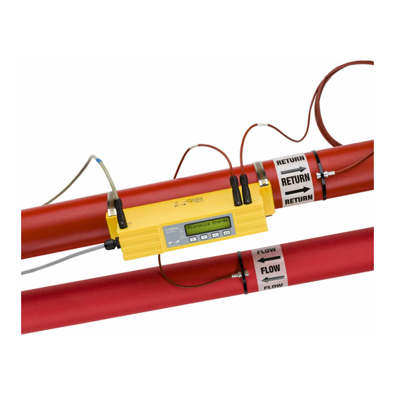
Page 7: Package Contents
Micronics U1000MKII User Manual Package Contents The unit consists of two parts: Electronics Module Consisting of the keypad and display, power, signal and comms connections. The Electronics Module clips onto the Sensor Assembly. Sensor Assembly Incorporating guide rails and two transducers for flow measurement. -
Page 8: Display
U1000MKII User Manual Micronics Display Flow Signal strength Flow Units Flow Direction Measured flow. For accurate Units applicable to * Indicates positive results, must be flow measured flow. over 40%. ! Indicates reversed flow. 4-20mA (1.) 4-20mA function is Enabled. -
Page 9: Installation
Important: Do not expect to obtain accurate results if the unit is positioned close to any obstruction that distorts the uniformity of the fluid flow profile. Micronics ltd accepts no responsibility or liability if product has not been installed in accordance with these instructions. -
Page 10: Clean The Pipe's Flow Sensor Contact Area
U1000MKII User Manual Micronics 2.1.2 Clean the Pipe's Flow Sensor Contact Area Prepare the pipe by removing any paint and degreasing the area to be installed to obtain the best possible surface. A smooth contact between pipe surface and the face of the sensors is an... -
Page 11: Pulse Output Connection
Micronics U1000MKII User Manual 2.2.2 Pulse Output Connection The isolated pulse output is provided by a SPNO/SPNC MOSFET relay which has a maximum load current of 500 mA and maximum load voltage of 24 V AC/DC. This output is suitable for SELV circuits only. -
Page 12: Switch On
The initial screen sequence is different for the FM and HM models. 2.3.1 U1000MkII-FM Switch on the power to the Electronics Module. A Micronics start-up screen is displayed for 5 seconds followed by hardware and software version information. You are then prompted to enter the internal diameter... - Page 13 Micronics U1000MKII User Manual The unit now shows the flow sensor separation Set Separation: Code Make a note of the Code. Is needed during the installation. All subsequent start-ups will use the same configuration. Continue with the installation of the Sensor Assembly (see page 12).
-
Page 14: U1000Mkii-Hm
U1000MKII User Manual Micronics 2.3.2 U1000MkII-HM Switch on the power to the Electronics Module. A Micronics start-up screen is displayed for 5 seconds followed by hardware and software version information. You are then prompted to enter the internal diameter Enter Pipe ID: of the pipe: 050.0 mm... - Page 15 Micronics U1000MKII User Manual For Water the Temperature range is entered Temperature: For a temperature of <= 40.0 °C select “COLD”. HOT | COLD For a temperature of > 40.0 °C select “HOT”. The unit now shows the correct flow sensor Set Separation: separation (in this case, “B-2”) for the chosen values...
-
Page 16: Adjust Flow Sensor Separation
U1000MKII User Manual Micronics 2.4 Adjust Flow Sensor Separation Using the separation code displayed by the Electronics Module, take the Sensor Assembly and adjust the flow sensor separation accordingly: Adjust the screws on the flow sensors as to allow sideways movement. DO NOT fully unfasten or remove the screws at this stage. -
Page 17: Pipe Adaptors
Micronics U1000MKII User Manual 2.6.1 Pipe Adaptors The diagrams below show how the adaptors are fitted. The top ‘V’ shaped adaptor clips onto the ends of the Sensor Assembly and this should be used with all pipes with an outside diameter less than 60 mm. -
Page 18: Remove Sensor-Holding Screws
U1000MKII User Manual Micronics Using the hose clips provided, clamp the Sensor Assembly (and adaptors, if used) to the pipe at an angle of 45° to the top of the pipe. Experience has shown that the most consistently accurate results are achieved when the unit is mounted at this angle. This minimises the effect of any flow turbulence resulting from entrained air along the top of the pipe and sludge at the bottom. -
Page 19: Connect Electronics Module
Micronics U1000MKII User Manual 2.8 Connect Electronics Module Ensure that the power is switched off. Connect the Electronics Module. The two leads can be connected either way round. The SMB connections are fragile so be careful when installing not to snap them off. -
Page 20: Clip Electronics Module To Sensor Assembly
U1000MKII User Manual Micronics Enter the password-controlled menu and scroll to the Calibration sub-menu. Press the Enter key until the Zero Temp Offset screen is displayed. Select Yes and press the Enter key to display the Attach Sensors screen. Press the Enter key again and wait for instrument to return to the Zero Temp Offset screen. - Page 21 Micronics U1000MKII User Manual Note: The fluid in the pipe must be in a stationary condition, if there is flow running in the pipe and the zero flow is set it will either result in an error if the flow is high enough or it will zero out the current flow value.
-
Page 22: Menu Structures
U1000MKII User Manual Micronics 3 MENU STRUCTURES The password-protected menus allow you to change the default settings: Accessing the Menus Ensure that the instrument is in Flow Reading, Total Flow, Temperature dT, Total Energy, Instant Power or Total Flow modes, then press Sig:87% 246.3... -
Page 23: Setup Menu Metric
Micronics U1000MKII User Manual 3.2 Setup Menu Metric Select Dims: mm | inches Enter Pipe ID: 050.0 mm Select Reading: Flow | Vel System Units: Litres | m3 Flow Units: Flow Units: m3/min | m3/h l/min | l/s Pipe Material:... -
Page 24: Setup Menu Imperial
U1000MKII User Manual Micronics 3.3 Setup Menu Imperial Select Dims: mm | inches Enter Pipe ID: 1.969 inches Select Reading: Flow | Vel System Units: impgal | USgal Flow Units: Flow Units: gal/min | gal/h USgal/m | USgal/h Pipe Material:... -
Page 25: Volume Total Menu
Micronics U1000MKII User Manual 3.4 Volume Total Menu Reset Vol. Total: NO | YES Set Total Form: Float User Menu: Volume totals 3.5 Current Output Menu Select 4-20mA: ON | OFF Flow @ 20mA: 1000.0 l/m Flow @ 4mA: 0000.0 l/m... -
Page 26: Pulse Output Menu
U1000MKII User Manual Micronics 3.6 Pulse Output Menu NOTE: SCREENS WITHIN THE RED BOX ARE ONLY SHOWN ON U1000MKII-HM MODELS. Select Pulse: ON | OFF Pulse Type: Pulse Type: Pulse Type: Pulse Type: Flow Alarm Energy Volume Frequency Volume per Pulse... -
Page 27: Calibration Menu
Micronics U1000MKII User Manual 3.7 Calibration Menu Note: Screens within the red box are only shown on U1000mkII-HM models. Damping Time [s]: Damping Time [s]: Damping Time [s]: Zero Cut-off: 0.01 m/s Clear Damping Time [s]: Zero Offset Zero Offset: Averaging…9... -
Page 28: Diagnostics Menu
U1000MKII User Manual Micronics 3.8 Diagnostics Menu The diagnostics menu provides some additional information about the flowmeter and its setup. The menu can be accessed by pressing the key from the main flow-reading screen. Press the keys to move between the diagnostics screens. -
Page 29: Outputs
Micronics U1000MKII User Manual 4 OUTPUTS Pulse Output Pulse output can be set up to operate one of five modes: • Volumetric • Energy (U1000MkII-HM only) • Frequency • Low Flow Alarm • Loss of Flow (Signal) Alarm The Alarm functions allow you to set the alarm switch to Normally Open or Normally Closed. -
Page 30: Energy Pulse (U1000Mkii-Hm Only)
U1000MKII User Manual Micronics 4.1.3 Energy Pulse (U1000MkII-HM only) When the Pulse Output is set to Energy, the kWh LED will be permanently illuminated. Choose from 1,10,100 kWh or 1 MWh when in metric mode and 1,10,100 kBTU or 1 MBTU in imperial mode. -
Page 31: Calibration
Micronics U1000MKII User Manual 5 CALIBRATION Where the unit is factory calibration checked for compliance, the installation should also be verified by means of a calibrated reference meter and the unit calibration adapted to match should it be required. Page 27... -
Page 32: Relocating The Unit
U1000MKII User Manual Micronics 6 RELOCATING THE UNIT If it is necessary to relocate the unit use the following procedure: Disconnect the temperature sensors (U1000MkII-HM only) and MODBUS cable (if used). Unfasten hose clips and remove the complete unit from the pipe. -
Page 33: Troubleshooting The Installation
7.6 Positioning For accurate measurements, the U1000MKII-FM/U1000MKII-HM must be installed at a position where the fluid flows uniformly. Flow profile distortions can result from upstream disturbance such as bends, tees, valves, pumps and other similar obstructions. To ensure a uniform flow profile, the unit must be mounted away from any cause of flow disturbance. - Page 34 Important: Do not expect to obtain accurate results if the unit is positioned close to any obstruction that distorts the uniformity of the flow profile. Micronics ltd accepts no responsibility or liability if product has not been installed in accordance with these instructions.
-
Page 35: Flow Reading When The System Is Closed
Again this can vary as levels are topped-up. 7.11 Limitations with composite pipes Testing has show that there is limited compatibility with the Micronics ultrasonic flowmeters when being used with a multi-layer composite pipe. The construction of the pipe doesn’t allow signals to propagate in the desired manner therefore the signals can either arrive in an unexpected location or the signal is so diminished that there is no information to process. -
Page 36: Appendix
U1000MKII User Manual Micronics 8 APPENDIX Specification General Measuring Technique Transit time Measurement channels Timing Resolution ±50 ps Turn down ratio 100:1 Flow velocity range 0.1 to 10 m/s Applicable Fluid types Clean water with < 3% by volume of particulate content, or up to 30% ethylene glycol. - Page 37 Micronics U1000MKII User Manual continued from previous page Modbus Format Baud rate 1200, 2400, 4800, 9600, 19200, 38400 Data-Parity-StopBits 8-None-2, 8-None-1, 8-Odd-2, 8-Even-1 Standards PI–MBUS–300 Rev. J Physical connection RS485 M-Bus Baud rates 300, 2400 & 9600 Data–Parity-StopBits 8-Even-1 Standards...
-
Page 38: Default Values
U1000MKII User Manual Micronics 8.2 Default values The settings will be configured at the factory for metric units. The following table lists the metric and imperial default values. Parameter Default Value Metric Imperial Dimensions inches Flow Units l/min USgal/min Pipe size (ID) 1"... -
Page 39: Data Entry Errors
Micronics U1000MKII User Manual 8.2.1 Data Entry Errors These generally advise you that the data entered is not within the specified range (Replace with Imperial units as needed): Displayed when an invalid Pipe ID is entered, prompting the user Range 20.0–165.1 to enter a value between 20 and 165 mm, depending on the 0.000 mm...
Need help?
Do you have a question about the U1000MKII-FM and is the answer not in the manual?
Questions and answers