Table of Contents
Advertisement
Advertisement
Table of Contents
Troubleshooting

Related Manuals for Micronics portaflow 220


Summary of Contents for Micronics portaflow 220
- Page 1 PORTAFLOW 220 Portable Ultrasonic Flowmeter User Manual Micronics Ltd, Knaves Beech Business Centre, Davies Way, Loudwater, High Wycombe, Bucks HP10 9QR. Telephone: +44 (0)1628 810456 Facsimilie: +44 (0)1628 531540 E-mail: sales@micronicsltd.co.uk www.micronicsflowmeters.com...
-
Page 3: Table Of Contents
3.5.5 Adjusting the damping factor 3.6 Performing Monitoring Functions 3.6.1 How to measure totalised flows (manually) 3.7 Configuring the Portaflow 220 Interfaces 3.7.1 How to turn the 4-20mA output OFF/ON 3.7.2 4-20mA signal calibration and ranging 3.7.3 How to convert the measured current to flow rate 3.7.4 How to turn the pulse output OFF/ON... - Page 4 4: Maintenance & Repair 5: Troubleshooting 5.1 Overview 5.2 General Troubleshooting Procedure 5.3 Warning & Status Messages 5.4 Test Block 5.5 Microprocessor Reset Facility 5.6 Diagnostics Display Appendix A: Specification Portaflow 220 User Manual (Issue 1.0)
-
Page 5: 1: General Description
The Portaflow 220 series comprises two models which are identical in operation but designed to be used with a different range of pipe diameters. The PF220A can be used with pipes in the range 13mm – 115mm and the PF220B with pipes in the range 50mm –... -
Page 6: Principles Of Operation
The Portaflow 220 system employs two ultrasonic transducers attached to the pipe carrying the liquid and compares the time taken to transmit an ultrasound signal in each direction. If the sound characteristics of the fluid are known, the Portaflow microprocessor can use the results of the transit time calculations to compute the fluid flow velocity. -
Page 7: Supplied Hardware
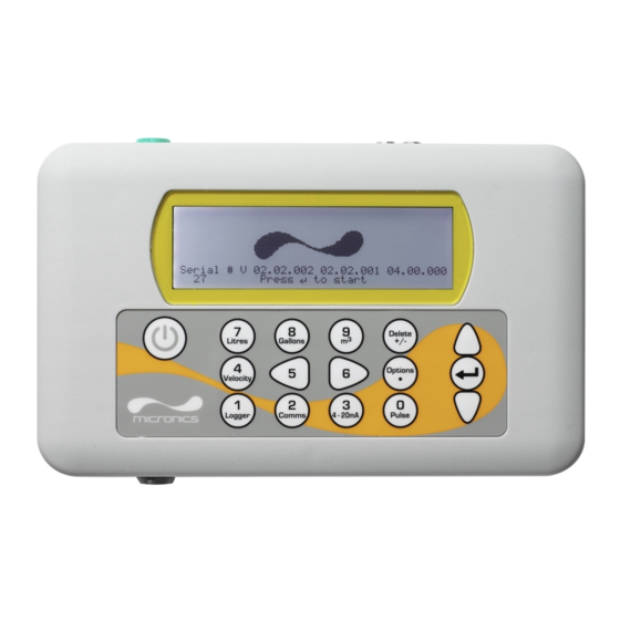
Portaflow 220 Instrument Figure 1.2 Standard Portaflow equipment Standard equipment • Portaflow 220 instrument with backlit graphic display. • Power supply - with UK, US, European adaptors. 110/240VAC. • 4-20mA/Pulse Output cable, USB cable and RS232-C cable. • 2 lengths of chain. -
Page 8: Portaflow 220 Instrument
1.3. A single cable that can be adapted for use for either of these output functions is included in the Portaflow 220 kit. The ‘tails’ on the free end of the cable must be terminated to suit the intended application. -
Page 9: Keypad
Menus and the menu selection keys The Portaflow 220 menus are arranged hierarchally with the MAIN MENU being at the top level. Menu navigation is achieved by three keys on the right hand side of the keypad which are used to scroll UP and DOWN a menu list and SELECT a menu item. -
Page 10: Power Supply And Battery Charging
Key Point: Always use the transducers that were supplied with the instrument. Transducer set 'A' Supplied as standard on PF220A for use on pipes 13mm to 115mm outside diameter. Transducer set 'B' Supplied as standard PF220B for use on pipes 50mm to 1000mm outside diameter. Portaflow 220 User Manual (Issue 1.0) -
Page 11: 2: Installation
5 diameters downstream, but when the transducers are positioned this close to any obstruction the resulting errors can be unpredictable. Key Point: Do not expect to obtain accurate results if the transducers are positioned close to any obstructions that distort the uniformity of the flow profile. Portaflow 220 User Manual (Issue 1.0) -
Page 12: Transducer Attachment
Slide the other end of the separation bar into the front of the right hand guide rail, align the front edge of the guide rail to the required separation distance (obtained from the Portaflow instrument) on the ruler (F), then secure it in place by tightening the thumbscrew. Portaflow 220 User Manual (Issue 1.0) -
Page 13: Fitting The Transducers
Repeat the above steps for the second transducer. Connect the transducers to the Portaflow instrument using the coaxial cables provided. The RED cable must be connected to the upstream transducer and the BLUE cable to the downstream transducer. Portaflow 220 User Manual (Issue 1.0) - Page 14 2: Installation Portaflow 220 User Manual (Issue 1.0)
-
Page 15: 3: Operating Procedures
Set-up a monitoring application (Paragraph 3.7) (Paragraph 3.6) How to measure totalised flows – Paragraph 3.6.1 4-20mA ON/OFF – Paragraph 3.7.1 4-20mA Calibration – Paragraph 3.7.2 Pulse ON/OFF – Paragraph 3.7.4 Pulse calibration – Paragraph 3.7.5 Portaflow 220 User Manual (Issue 1.0) -
Page 16: Setting-Up The Instrument
Setting-up the Instrument 3.1.1 Using the instrument for the first time Before you use your Portaflow 220 for the first time you should first charge the battery, then select the display language and set-up the internal clock, as described below. -
Page 17: Enabling/Disabling The Backlight
Portaflow system and access the FLOW READING screen. If the point at which you intend to take the measurement is likely to require regular monitoring it is best to set it up as a ‘Site’ within the Portaflow 220, which then stores the site parameters (See Paragraph 3.4). - Page 18 If the material is not listed select Other and Mild Steel enter the propagation rate of the pipe wall S' less Steel 316 material in metres/sec. Contact Micronics if S' less Steel 303 this is not known. Plastic Cast Iron...
- Page 19 18. Once the transducers have been fitted and connected press the Enter key. Please wait.. 19. This will take you from the SENSOR Checking signals SEPARATION screen to the FLOW READING **************************************** screen via a signal-checking screen (shown here). **************************************** Portaflow 220 User Manual (Issue 1.0)
-
Page 20: Using The System At A Regularly Monitored Location
ENTER key. Enter the new temperature value and press °C: 5.00 the ENTER key. °F: 41.00 Continue.. The new temperature should now be indicated in both °C and °F. 10. Select Continue.. and press ENTER. Portaflow 220 User Manual (Issue 1.0) -
Page 21: Managing Named Sites
If you want to monitor a particular site location frequently you can set up a named ‘Site’ to store the installation details, such as pipe dimensions and material, required to set-up the Portaflow 220 system. These can then be recalled later when revisiting that particular location. -
Page 22: Setting Up A New Site
MENU. Note: The ‘Download & save current site’ option is disabled in the Portaflow 220 range. 3.4.2 Changing a site name To change a site name use the same method described above for generating a new site: but in this case select a current site name to change rather than an EmptySite. -
Page 23: Instrument Calibration
Press ENTER on the subsequent screen to Totaliser accept the change, which will return you to Reset +Total the screen shown. Scroll down to select Exit and press ENTER to return to the FLOW READING screen. Portaflow 220 User Manual (Issue 1.0) -
Page 24: Adjusting The Calibration Factor
In most situations it is not possible to inspect the pipe internally and the true condition is not known. In these circumstances experience has shown that the following values can be used: Pipe Material Roughness Factor Non ferrous metal 0.01 Glass Plastics Light metal Portaflow 220 User Manual (Issue 1.0) -
Page 25: Adjusting The Damping Factor
1.000 Roughness factor 0.01 Diagnostics Exit Key Point: If the damping factor is set too high the value displayed may appear stable but it may exhibit large step changes when the value is updated. Portaflow 220 User Manual (Issue 1.0) -
Page 26: Performing Monitoring Functions
If, for operational reasons, you want to stop the totaliser function temporarily set the Totaliser option to Stall in the FLOW READING OPTIONS screen as described above. This will stop the totaliser operation without affecting its current values. Portaflow 220 User Manual (Issue 1.0) -
Page 27: Configuring The Portaflow 220 Interfaces
3: Operating Procedures Configuring the Portaflow 220 Interfaces 3.7.1 How to turn the 4-20mA output OFF/ON 4-20 mA OUTPUT DD-MM-YY HH:MM:SS With the instrument operating in the FLOW 4-20 mA O/P is ON Dim: mm READING mode, press the 4-20mA function mA Output Reading 0.00... -
Page 28: How To Convert The Measured Current To Flow Rate
To calculate the flow rate (l/min) for a measured current I(mA) then: 0-20mA 0-16mA 4-20mA × × × – – – – Flow rate -------------------------------------------------------- - Flow rate ------------------------------------------ - Flow rate ------------------------------------------ - Portaflow 220 User Manual (Issue 1.0) -
Page 29: How To Turn The Pulse Output Off/On
Select a Pulse width (in ms) to suit the particular application – e.g. electro-mechanical counter. Refer to the manufacturer’s data sheet for the minimum pulse width. Select Exit and press ENTER to return to the FLOW READING screen. Portaflow 220 User Manual (Issue 1.0) - Page 30 3: Operating Procedures Portaflow 220 User Manual (Issue 1.0)
-
Page 31: 4: Maintenance & Repair
The instrument and sensors should be calibrated at least once every 12 months. Contact Micronics or your local service agent for details. 10. When returning product to Micronics make sure it is clean and please notify Micronics if the instrument has been in contact with any hazardous substances. - Page 32 4: Maintenance & Repair Portaflow 220 User Manual (Issue 1.0)
-
Page 33: 5: Troubleshooting
• Very hot pipe almost turns water to steam and therefore exhibits the wrong speed characteristics – could be due to reduced pipe pressure. • Flashover – liquid turns into a gas because of lower than required pressure. Portaflow 220 User Manual (Issue 1.0) -
Page 34: General Troubleshooting Procedure
Ensure pipe diameter within specifications of the selected transducers. Check instrument using test block. Ensure the pipe is completely full. Ensure pipe surface is not corroded, or protective surface loose. Check for particles in the fluid. Figure 5.1 Troubleshooting chart Portaflow 220 User Manual (Issue 1.0) -
Page 35: Warning & Status Messages
Enter a valid number. Pulse width error You have entered an out-of-range value in the Pulse width Interpretation: error field in the PULSE OUTPUT menu – see Paragraph 3.7.5. Response: Enter a valid number. Portaflow 220 User Manual (Issue 1.0) - Page 36 The selected temperature is higher than the maximum allowed for the sensor type. Response: Enter a different temperature. Mode: Err Typ Interpretation: The selected sensors are invalid and the mode cannot be verified. Response: Select a mode that gives a non-zero separation distance. Portaflow 220 User Manual (Issue 1.0)
-
Page 37: Test Block
Connect the sensors to the Portaflow 220 instrument using the cables provided. 10. Press ENTER to go to the FLOW READING screen. -
Page 38: Microprocessor Reset Facility
14. The signal strength indicator at the left of the display should show 3–4 bars. Microprocessor Reset Facility In the rare event that the Portaflow 220 instrument appears to totally hang-up, or displays total gibberish, you can reset its microprocessor by carefully inserting a straightened paperclip into the pinhole located in the right-hand side of the instrument to operate the internal reset switch. -
Page 39: Appendix A: Specification
Pipe Lining Thickness: 0mm – 10mm. Pipe Wall Temperature Range: Sensor operating temperature is -20°C to +135°C. TRANSDUCER SETS Standard transducers: Temperature Range -20°C to +135°C. PF220A – Type 'A-ST' (2MHz). PF220B – Type 'B-ST' (1MHz). Portaflow 220 User Manual (Issue 1.0) - Page 40 All components are contained in a hard-wearing polyproylene carrying case with a protective moulded foam insert. Enclosure: Material: Flame retardant injection moulded ABS. Dimensions: 264mm x 168mm x 50mm. Weight (Including Battery): 1.1 kg. Protection: IP54. Portaflow 220 User Manual (Issue 1.0)
- Page 41 EN61204 - 3. SHIPPING INFORMATION Box Dimensions: 505mm x 125mm x 420mm. Weight: 6.0 kg. Volumetric Weight: 4.5 kg. Micronics reserve the right to alter any specification without notification. PORTAFLOW™ 220 and PF220 are identical. Portaflow 220 User Manual (Issue 1.0)
- Page 42 A: Specification Portaflow 220 User Manual (Issue 1.0)
- Page 43 A: Specification CE Declaration of Conformity Portaflow 220 User Manual (Issue 1.0)
- Page 44 A: Specification Portaflow 220 User Manual (Issue 1.0)
Need help?
Do you have a question about the portaflow 220 and is the answer not in the manual?
Questions and answers