Table of Contents
Advertisement
Quick Links
PORTAFLOW 220
Portable Ultrasonic Flowmeter
User Manual
Micronics Ltd, Knaves Beech Business Centre, Davies Way, Loudwater,
High Wycombe, Bucks HP10 9QR.
Telephone: +44 (0)1628 810456 Facsimile: +44 (0)1628 531540 E-mail: sales@micronicsltd.co.uk
www.micronicsflowmeters.com
Issue 1.8
(Software Ver. 02.07.005 and 02.07.006)
Advertisement
Table of Contents

Related Manuals for Micronics PF222


Summary of Contents for Micronics PF222
- Page 1 PORTAFLOW 220 Portable Ultrasonic Flowmeter User Manual Micronics Ltd, Knaves Beech Business Centre, Davies Way, Loudwater, High Wycombe, Bucks HP10 9QR. Telephone: +44 (0)1628 810456 Facsimile: +44 (0)1628 531540 E-mail: sales@micronicsltd.co.uk www.micronicsflowmeters.com Issue 1.8 (Software Ver. 02.07.005 and 02.07.006)
-
Page 3: Table Of Contents
Table of Contents 1: General Description 1.1 Introduction 1.2 Principles of Operation 1.3 Supplied Hardware 1.4 Portaflow 220 Instrument 1.4.1 Connectors 1.4.2 Keypad 1.4.3 Power supply and battery charging 1.5 Transducers 2: Installation 2.1 Transducer Positioning 2.2 Transducer Attachment 2.2.1 Preparation 2.2.2 Attaching the guide rails 2.2.3 Fitting the transducers 3: Operating Procedures... - Page 4 4: Maintenance & Repair 5: Troubleshooting 5.1 Overview 5.2 General Troubleshooting Procedure 5.3 Warning & Status Messages 5.4 Test Block 5.5 Microprocessor Reset Facility 5.6 Diagnostics Display Appendix A: Specification Port aflow 220 User Manual ( I ssue 1.8) ( Soft ware Ver. 02.07.005 and 02.07.006)
-
Page 5: 1: General Description
1: General Description Introduction This manual describes the operation of the Micronics Portaflow 220 portable flowmeter. The flowmeter is designed to work with clamp-on transducers to enable the flow of a liquid within a closed pipe to be measured accurately without needing to insert any mechanical parts through the pipe wall or protrude into the flow system. -
Page 6: Principles Of Operation
1: General Description Principles of Operation When ultrasound is transmitted through a liquid the speed at which the sound travels through the liquid is accelerated slightly if it is transmitted in the same direction as the liquid flow and decelerated slightly if transmitted against it. -
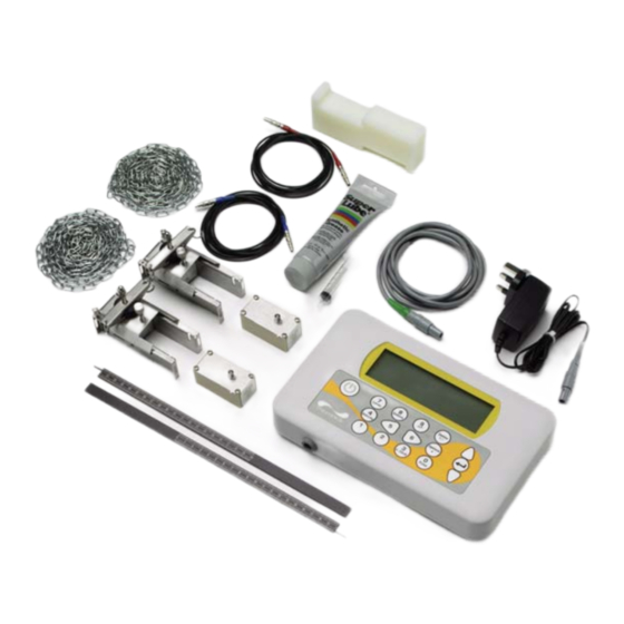
Page 7: Supplied Hardware
1: General Description Supplied Hardware The Portaflow equipment is supplied in a rugged polypropylene carrying case fitted with a foam insert to give added protection for transportation. The supplied components are shown in Figure 1.2. Test Block Transducer Cables (x2) Chains (x2) Ultrasonic Couplant... -
Page 8: Portaflow 220 Instrument
1: General Description Portaflow 220 Instrument The Portaflow 220 is a microprocessor controlled instrument operated through a menu system using an inbuilt LCD display and keypad. It can be used to display the instantaneous fluid flow rate or velocity, together with totalised values. -
Page 9: Keypad
1: General Description Numerical keypad with dual function keys ON/OFF Scroll UP ENTER (SELECT) Scroll DOWN Scroll LEFT Scroll RIGHT Figure 1.4 Keypad 1.4.2 Keypad The instrument is configured and controlled via a 16-key tactile membrane keypad, as shown in Figure 1.4. -
Page 10: Power Supply And Battery Charging
1: General Description 1.4.3 Power supply and battery charging Operating power is provided by an internal battery that can be charged from the utility supply using the supplied external charger. When you first receive the unit you must put the battery on charge for a minimum of 6.5hrs before use. -
Page 11: 2: Installation
Micronics limited accepts no responsibility or liability if product has not been installed in accordance with the installation instructions applicable to the product. -
Page 12: Transducer Attachment
2: Installation Transducer Attachment The transducers are fitted to adjustable guide rails which are secured to the pipe using wrap-around chains and mechanically connected together by a steel separation bar. The separation bar also acts as a ruler to allow the distance between the transducers to be accurately set to the value determined by the Portaflow instrument. -
Page 13: Fitting The Transducers
2: Installation On each guide rail, attach one end of a securing chain to a hook on the tensioning bar (B), wrap the chain (G) around the pipe and then attach it to the hook on the other end of the tensioning bar whilst keeping the chain as tight as possible. - Page 14 2: Installation Port aflow 220 User Manual ( I ssue 1.8) ( Soft ware Ver. 02.07.005 and 02.07.006)
-
Page 15: 3: Operating Procedures
3: Operating Procedures Initial instrument setup (Paragraph 3.1) Battery charging, Set date/time, Language, Backlight Connect and take basic flow readings At a one-off location At a frequent location Manage site details (Paragraph 3.2) (Paragraph 3.3) (Paragraph 3.4) QUICK START VIEW EDIT SITE DATA Set up a named site Rename a site Enter data... -
Page 16: Setting-Up The Instrument
3: Operating Procedures Setting-up the Instrument 3.1.1 Using the instrument for the first time Before you use your Portaflow 220 for the first time you should first charge the battery, then select the display language and set-up the internal clock, as described below. Charging the battery Connect the external battery charger to the charger socket at the bottom of the instrument then switch on the utility supply. -
Page 17: Enabling/Disabling The Backlight
3: Operating Procedures Setting the Date & Time SETUP INSTRUMENT DD-MM-YY HH:MM:SS Select Setup Instrument from the MAIN Qxx.xx% MENU. The screen shown here should be Set Date & Time : dd-mm-yy hh:mm:ss displayed. Calibrate 4-20mA Select Set Date & Time and press the Pulse status Backlight Disabled... -
Page 18: Using The Quick Start Menu
3: Operating Procedures Using the Quick Start Menu If you want to perform a ‘one-off’ flow reading at a particular pipe location the Quick Start menu provides the quickest way to set up the Portaflow system and access the FLOW READING screen. If the point at which you intend to take the measurement is likely to require regular monitoring it is best to set it up as a ‘Site’... - Page 19 If the material is not listed select Other and Mild Steel enter the propagation rate of the pipe wall S' less Steel 316 material in metres/sec. Contact Micronics if S' less Steel 303 this is not known. Plastic Cast Iron...
- Page 20 3: Operating Procedures 15. The SENSOR SEPARATION screen now SENSOR SEPARATION DD-MM-YY HH:MM:SS Site : Quickstart displays a summary of the entered Pipe : 58.00 mm parameters and informs you of the mode of Wall : 4.00 operation and the distance to set up between Sensors : A-ST Reflex...
-
Page 21: Using The System At A Regularly Monitored Location
3: Operating Procedures Using the System at a Regularly Monitored Location Setting up the Portaflow system using the Quick Start method described in Paragraph 3.2 is easy and the recommended method to use in a ‘one-off’ situation. But if you have a site location that you want to monitor on a frequent basis it is better to set up a named ‘Site’... -
Page 22: Managing Named Sites
3: Operating Procedures 12. Take a note of the displayed parameters, ATTACH SENSORS DD-MM-YY HH:MM:SS then press the ENTER key. 13. The ATTACH SENSORS screen displays, Attach Sensor Set giving instructions to attach the sensors. Red Connector UpStream Press key to go to Flow Reading Note: If you press the ENTER key before the transducers are fitted and connected to the instrument, the instrument will detect a low signal strength and may indicate an ERROR condition. -
Page 23: Setting Up A New Site
3: Operating Procedures 3.4.1 Setting up a new site VIEW EDIT SITE DATA DD-MM-YY HH:MM:SS Select View / Edit Site Data from the Qxx.xx% MAIN MENU. Choose from list of sites Select Choose from list of sites. Site name : EmptySite1 Dimensions : mm Select one of the EmptySites from the... -
Page 24: Instrument Calibration
3: Operating Procedures Instrument Calibration The Portaflow is fully calibrated before it leaves the factory; however the following adjustments are provided to allow you to further ‘fine tune’ your instrument to suit local conditions and application where necessary. Apart from the zero flow offset adjustment, these are normally carried out only where the instrument is to be used in a permanent or semi-permanent location. -
Page 25: Adjusting The Calibration Factor
3: Operating Procedures Ke y Point : I n order t o cancel any applied offset you m ust eit her read t he flow via Quick Start or swit ch t he Port aflow inst rum ent OFF & ON. Any value t hat you t rim - out using t he offset adj ust m ent will be added/ subt ract ed from t he flow reading across t he whole range. -
Page 26: Adjusting The Damping Factor
3: Operating Procedures Pipe Material Roughness Factor Drawn steel pipes: 0.01 • Fine planed, polished surface • Plane surface • Rough planed surface Welded steel pipes, new: • Long usage, cleaned • Lightly and evenly rusted • Heavily encrusted Cast iron pipes: •... -
Page 27: Performing Monitoring Functions
3: Operating Procedures Select the value of the Damping factor DAMPING OPTIONS DD-MM-YY HH:MM:SS as required to remove any unwanted display 1 second fluctuations. Increasing the value applies a 10 seconds greater smoothing affect. 15 seconds Press the ENTER key to apply the selection 20 seconds and return to the FLOW READING OPTIONS 30 seconds... -
Page 28: Configuring The Current / Pulse Output
3: Operating Procedures 11. Scroll down and select Exit then press the FLOW READING DD-MM-YY HH:MM:SS Qxx.xx% ENTER key to return to the FLOW READING Signal screen which will now indicate the 12.34 instantaneous flow together with the l/min totalised flow. Note that in some installation the measured +Total: 300.0 litres... - Page 29 3: Operating Procedures 4-20mA signal calibration and ranging Ke y Point : The 4- 20m A out put has been calibrat ed at t he fact ory and should not require furt her adj ust m ent . I n t he rare event t hat re- calibrat ion is necessary, t his procedure should be carried out only by a t rained engineer.
-
Page 30: Pulse Output
3: Operating Procedures 10. Select Output mA for error and enter a value (default is 22mA) that you want the 4-20mA output to produce in the event of an error (e.g. if the flow-rate is outside the set range). 11. Upon completion press the ENTER key to return to the FLOW READING screen. Converting the measured current to flow rate Assume the maximum flow rate is (l/min) and the minimum flow rate... - Page 31 3: Operating Procedures Turning the pulse output OFF/ON (volumetric mode) PULSE OUTPUT DD-MM-YY HH:MM:SS With the instrument operating in the FLOW Pulse output is ON Qxx.xx% READING mode, press the Pulse function Flow units litres key to access the PULSE OUTPUT screen. Output A Pulse output is ON (or OFF) Vol per pulse...
- Page 32 3: Operating Procedures Selecting the pulse output frequency mode PULSE OUTPUT DD-MM-YY HH:MM:SS With the instrument operating in the FLOW A1 Pulse Frequency is ON Qxx.xx% READING mode, press the Pulse function Flow units litres key to access the PULSE OUTPUT screen. Output Frequency To change the pulse output to ‘frequency’...
- Page 33 The instrument and sensors should be calibrated at least once every 12 months. Contact Micronics or your local service agent for details. 10. When returning product to Micronics make sure it is clean and please notify Micronics if the instrument has been in contact with any hazardous substances.
- Page 34 4: Maintenance & Repair Port aflow 220 User Manual ( I ssue 1.8) ( Soft ware Ver. 02.07.005 and 02.07.006)
- Page 35 5: Troubleshooting Overview If you have a problem with your flow monitoring system it can be due to any of the following: Faulty instrument If you suspect the instrument is faulty you can check it out using a test block as described in Paragraph 5.4.
- Page 36 5: Troubleshooting General Troubleshooting Procedure START Recharge the battery. Is the display blank? If battery won't recharge then replace the charger (if faulty) or return the instrument for repair. Turn instrument OFF/ON. Is the display If the display is still scrambled/ scrambled or hung up press the microprocessor hung up?
- Page 37 5: Troubleshooting Warning & Status Messages FLOW RATE ERRORS No flow signal Interpretation: This message appears when the transducers cannot send or receive signals to each other. Response: Firstly check that all cables are connected, transducers are on the pipe correctly with sufficient couplant on the face.
- Page 38 5: Troubleshooting 4-20mA ERRORS Interpretation: The actual flow is higher than the maximum set on the mA range. mA out > Max Response: Re-scale the 4-20mA output to be able to cope with the higher flow – see page 25. NOTE: The 4-20mA output is calibrated before the instrument leaves the factory and Calibration 20mA Error!
- Page 39 5: Troubleshooting BATTERY ERRORS Interpretation: The battery has discharged to below 30% remaining. This leaves the Battery Low instrument with approximately 4 hours remaining, depending on power usage, before it needs recharging. Response: Recharge the internal battery at the earliest opportunity. Do not leave the instrument for a prolonged period with a fully discharged battery.
- Page 40 5: Troubleshooting 12. Select Exit and press the ENTER key to return to the FLOW READING menu. 13. The flow reading value displayed is not important. The fact that a reading is obtained indicates that the instrument is functioning. This value may fluctuate but this is normal. 14.
- Page 41 Appendix A: Specification GENERAL NEW! DSP Measurement Technique: Transit time. Timing Resolution: 50 pico-seconds, continuous signal level indication on display. Improved! Flow Velocity Range: Minimum Velocity 0.1m/s; Max Velocity 20m/s: Bi-directional. Turn Down Ratio: 100:1 Accuracy: ±0.5% to ±2% of flow reading for flow rate >0.2m/s and Pipe ID >75mm. ±3% of flow reading for flow rate >0.2m/s and Pipe ID in range 13mm - 75mm.
- Page 42 LANGUAGES Standard Supported Languages: English, French, German, Italian, Spanish, Portuguese, Russian, Norwegian, Dutch, Swedish. OUTPUTS Analogue Output: 4–20mA, 0–20mA, 0–16mA. Resolution: 0.1% of full scale. Alarm Currents: Any between 0–26mA. Isolation: 1500V Opto-isolated. Maximum Load: 620 Ohms. Pulse Output TTL: Opto-isolated MOSFET relay.
- Page 43 505mm x 125mm x 420mm. Weight: 6.0 kg. Volumetric Weight: 4.5 kg. Micronics reserve the right to alter any specification without notification. PORTAFLOW™ 220 and PF220 are identical. Port aflow 220 User Manual ( I ssue 1.8) ( Soft ware Ver. 02.07.005 and 02.07.006)
- Page 44 Port aflow 220 User Manual ( I ssue 1.8) ( Soft ware Ver. 02.07.005 and 02.07.006)
- Page 45 CE Declaration of Conformity Port aflow 220 User Manual ( I ssue 1.8) ( Soft ware Ver. 02.07.005 and 02.07.006)
- Page 46 Port aflow 220 User Manual ( I ssue 1.8) ( Soft ware Ver. 02.07.005 and 02.07.006)
Need help?
Do you have a question about the PF222 and is the answer not in the manual?
Questions and answers