Table of Contents

Subscribe to Our Youtube Channel
Related Manuals for Micronics PORTAFLOW 300


Summary of Contents for Micronics PORTAFLOW 300
- Page 1 PORTAFLOW 300 PORTAFLOW 300 PORTAFLOW 300 PORTAFLOW 300 Ultrasonic Flowmeter Manual Keison Products P.O. Box 2124, Chelmsford CM1 3UP, England Tel: +44 (0) 1245 600560 Fax: +44 (0) 1245 600030 Email: sales@keison.co.uk www.keison.co.uk...
-
Page 2: Table Of Contents
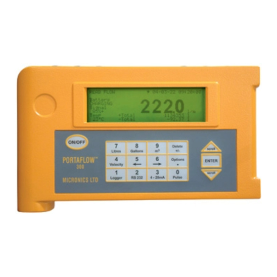
Options Key WARNING - Users should ensure or note that: The PORTAFLOW 300 is not certified for use in Hazardous areas. The local site safety regulations are complied with. Work is carried out in accordance with The Health & Safety at Work Act 1974. -
Page 3: Introduction
The PORTAFLOW™ 300 is a portable flowmeter 1. Switch on and press ENTER. 2. Check battery level - If the battery symbol designed by Micronics for use on liquid flows in on the display is full, the unit is charged, full pipes, which utilises “Clamp-On”... -
Page 4: Connectors
Parts and Accessories surface. The Portaflow 300 is supplied in a rugged IP68 carrying case. The equipment is housed in a 10. Press ENTER to read flow. foam insert inside the case to give added protection for transportation. -
Page 5: Charger
8hrs. If the 4-20mA is used Transducers constantly at 20mA, the battery life would The Portaflow 300 uses four different reduce by 20%. transducer sets. They are called ‘A’, ‘B’, ‘C’ and ‘D’. The instrument selects transducer The display in flow mode continually shows the sets, depending on the data entered (i.e. -
Page 6: Separation Distance
supplied when purchased, for the user to The separation distance is the distance program. between the front edge of each sensor block. See Figure 3, page 2, for an example in reflex Transducer sets are positioned in the guide mode. Connections are made via the IP66 rail, to help correctly align the transducer connectors between the sensor block and the blocks along the pipe axis. -
Page 7: Ultrasonic Couplant
(See pages 1). Fluid Types Portaflow 300 is capable of measuring clean liquids or oils that have less than 3% by volume of particulate content. Cloudy liquids like river water and effluent can be measured along with cleaner liquids, like demineralised water. -
Page 8: Programming/Main Menu
Use the scroll keys to select the required material then press ENTER. If Other is QUICK START yy-mm-dd hh:mm:ss selected, enter the propagation rate of the lining in metres/sec. Contact Micronics if this is Dimension units not known. MILLIMETRES Pipe outside diameter? - Page 9 scroll will prompt the user to enter a value. When a value is entered press ENTER. QUICK START yy-mm-dd hh:mm:ss ATTACH SENSORS yy-mm-dd hh:mm:ss Select pipe lining material: Steel No signal from temp sensor Rubber Glass Press ENTER to try again or Epoxy SCROLL to enter a value Concrete...
-
Page 10: View/Edit Site Data
List Sites propagation rate in m/s. This can be supplied Selecting LIST SITES allows the user to view by Micronics or found in the back of the the names of up to 20 sites, numbers 1-10 manual under Liquid Sound Speeds. -
Page 11: Select Sensor Set
ATTACH SENSORS yy-mm-dd hh:mm:ss SITE SENSOR ERROR yy-mm-dd hh:mm:ss Attach sensor set A in REFLEX mode Cannot READ FLOW because pipe is too large/small for sensor set Approx. max. flow: 7.22 m/s press ENTER to continue Press ENTER to continue or SCROLL to select another sensor Sensor Mode Selecting Sensor mode allows the user to... - Page 12 move in blocks of 60. Each point is equivalent to the time the user has programmed into the MAIN MENU yy-mm-dd hh:mm:ss instrument. i.e. if the instrument has been programmed to read every 10 minutes, every data point will be equivalent to whatever the reading was at that time.
- Page 13 Printer status: Busy means the unit is off line + flow or the buffer is full to the printer. The Portaflow 300 will continue to download the data until complete. Press SCROLL to exit max. and return to the MAIN MENU. Press ENTER + flow to stop downloading.
-
Page 14: Download To Windows 95
WINDOWS 95 Before downloading data onto a spreadsheet and Download range to RS232 is selected on the Portaflow 300, the data has to be stored to The heading Phone Number will appear. a file. Data cannot be entered onto a Select Connect using: then Direct to Com 2. - Page 15 Before downloading data onto a spreadsheet displayed. and Download range to RS232 is selected on the Portaflow 300, the data has to be stored to a file. Data cannot be entered onto a spreadsheet unless it has been stored to a file.
-
Page 16: Set Up Rs232
Note: Flow Control is also known as Handshaking or Protocol. Check now that the above settings are the same as the settings on the Portaflow 300. This can be done from Read flow mode using Main Menu - Set Up RS232... -
Page 17: Setup Portaflow
CALIBRATE 4-20mA yy-mm-dd hh:mm:ss Main Menu - Set Up Portaflow Set Date & Time Adjust the output current to 4mA When the cursor bar is on Set date and time Use UP/DOWN to set, 5/6 to trim press ENTER, the display will show. DAC value: 8590 mA OK SETUP PORTAFLOW yy-mm-dd hh:mm:ss... -
Page 18: Read Flow
ATTACH SENSORS yy-mm-dd hh:mm:ss Sensor Parameters This facility allows Micronics or the user to program the instrument to accept different FLUID TEMPERATURE (°C) 20.0 sensor sets in the future and when they become available. Instructions for this are Set sensor separation to 33.5... -
Page 19: Ma Output Key
DATA LOGGER yy-mm-dd hh:mm:ss Note: Memory free, List block names, Next block to view, View log as text, View log as Log name QUICK START graph, Units, Graph Y axis max, Clear log and Log data to MEMORY Exit are the same as described on page 10 - Logging interval 5 seconds Main Menu - Data Logger... -
Page 20: Rs232 Output Key
Max. pulse rate1 per sec displayed (See page 9 - Read Flow - Attach Litres per pulse12.76 sensors). Micronics cannot guarantee Exit measuring flows below this range, due to instabilities in the measurement system, but it is possible for the user to cancel any cut-off altogether. - Page 21 This is a point in the signal transmitted, where Reset + Total/- Total the flow measurement is taken from. It is used The Portaflow 300 has forward and reverse to see if the signal is being taken from the totalisers that can be reset when this option is burst, at the correct time to get the strongest selected.
-
Page 22: Messages
This value may be subject condition of the pipe being measured is poor. to errors due to small pipe dimension errors especially on smaller pipes. Micronics Warning Messages recommend the use of tabulated values (See page 27). -
Page 23: Application Information
The messages below appear mainly when data has been incorrectly entered or the W3: NO PROP SIGNAL Portaflow 300 is trying to be used on an This occurs when the fixed transducer is application that it is not capable of working on. -
Page 24: Transducer Positioning
‘B’ ‘A’ predetermined path. TRANSDUCER POSITIONING As the transducers for the Portaflow 300 are clamped to the outside surface of the pipe, the FLOW meter has no way of determining exactly what is happening to the liquid. The assumption... -
Page 25: Mounting The Transducers
Steel Pipes the amount of couplant It will be impossible to achieve the accuracy of applied is less critical, however do not use measurement specified for the Portaflow 300 if more than is absolutely necessary. the transducers are not clamped to the pipe correctly and if the data - I.D. -
Page 26: Liquid Conditions
4000-5000 the instrument calibration is no longer valid. If the Portaflow 300 is to be used on laminar flow applications it will be necessary to calculate the Reynolds No. When calculating the Reynolds No. it is necessary to know the Kinematic viscosity in Centistokes;... -
Page 27: Flow Range
from the pipe wall and consequently you will lose the signal. FLOW RANGE Figure 19 Transducer Set ‘A’ Transducer Set ‘C’ Diagonal 110mm Reflex 110mm Diagonal 2500mm Reflex 2500mm Reflex 89mm Diagonal 2000mm Reflex 2000mm Diagonal 50mm Diagonal 300mm Reflex 300mm Reflex 50mm Diagonal 150mm Reflex 150mm... -
Page 28: Liquid Sound Speeds
Liquid Sound Speeds at 25°C ∆ ∆ ∆ ∆ v/ºC -m/s/ºC Substance Form Index Specific Gravity Sound Speed Acetic anhydride (22) 1.082 (20ºC) 1180 Acetic acid, anhydride (22) 1.082 (20ºC) 1180 Acetic acid, nitrile 0.783 1290 Acetic acid, ethyl ester (33) 0.901 1085 Acetic acid, methyl ester... - Page 29 1,2-Dimethyl-benzene(29,46) 0.897 (20ºC) 1331.5 1,4-Dimethyl-benzene (46) 1334 2,2-Dimethyl-butane (29,33) 0.649 (20ºC) 1079 Dimethyl ketone 0.791 1174 Dimethyl pentane (47) 0.674 1063 Dimethyl phthalate 1463 Diiodo-methane 3.235 Dioxane 1.033 1376 Dodecane (23) 0.749 1279 3.85 1,2-Ethanediol 1.113 1658 Ethanenitrile 0.783 1290 Ethanoic anhydride (22) 1.082 1180...
- Page 30 Milk, homogenized 1548 Morpholine 1.00 1442 Naphtha 0.76 1225 Natural Gas (37) 0.316 (-103ºC) Neon (45) 1.207 (-246ºC) Nitrobenzene (46) 1.204 (20ºC) 1415 Nitrogen (45) 0.808 (-199ºC) Nitromethane (43) 1.135 1300 Nonane (23) 0.718 (20ºC) 1207 4.04 1-Nonene (27) 0.736 (20ºC) 1207 Octane (23) 0.703...
- Page 31 Toluol 0.866 1308 Tribromo-methane (46,47) CHBr 2.89 (20ºC) 1,1,1-Trichloro-ethane (47) 1.33 Trichloro-ethene (47) 1.464 1028 Trichloro-fluoromethane (3) (Freon 11) 1.49 828.3 3.56 Trichloro-methane (47) CHCl 1.489 1,1,2-Trichloro-1,2,2-Trifluoro-Ethane F-CClF 1.563 783.7 Triethyl-amine (33) 0.726 1123 4.47 Triethylene glycol 1.123 1608 1,1,1-Trifluoro-2-Chloro-2-Bromo-Ethane HClBrF 1.869 1,2,2-Trifluorotrichloro- ethane (Freon 113)
-
Page 32: Solid Sound Speeds
Solid Sound Speeds 1. Use Shear Wave for ‘A’ & ‘B’ Transducers 2. Use Long Wave for ‘C’ & ‘D’ Transducers Material Shear Wave m/s Long Wave m/s Steel 1% Carbon (hardened) 3150 5880 Carbon Steel 3230 5890 Mild Steel 3235 5890 Steel 1% Carbon... -
Page 33: Specification
5 x 4/3 AA nickel metal hydride 24-30 hrs continuous operating on fully charged battery cells Recharge time 10-16 hours External battery can be connected to the Portaflow 300 for remote flow monitoring (contact Micronics) OUTPUTS: Languages (optional) English/German/French Display... -
Page 34: Ce Marking Guidance Notes
CE MARKING The Portaflow 300 has been tested and found to conform to EN50081 - 1 Emission Standards and EN50082 - 1 Immunity Standards. The tests were conducted by AQL - EMC Ltd, of 16 Cobham Road, Ferndown Industrial Estate, Wimborne, U.K. -
Page 35: Battery Charge Procedure
PORTAFLOW 300 Battery Charge circuit Operation. Charging Controller IC: A Maxim IC MAX712 or MAX713 controls the Ni-Cd and Ni-Mh battery charger. It has two modes, fast charge and trickle charge; an output indicates the fast-charge status. In both modes it supplies, via a PNP power transistor, a constant current to the battery, by keeping a constant voltage across a current sensing resistor. - Page 36 The fastest way to fully charge the battery is to charge for 4.5 hrs, then switch the power supply off and on again, thus re-starting the fast charge for another 4.5 hr period, followed by trickle charge. Warning: If the battery is getting warm, that would indicate that it is full, and the power supply should not be connected again - overcharging reduces the life of the battery.
Need help?
Do you have a question about the PORTAFLOW 300 and is the answer not in the manual?
Questions and answers