
Related Manuals for IBASE Technology ISR215F


Summary of Contents for IBASE Technology ISR215F
- Page 1 ISR215F Ruggedized Edge Computer with NXP i.MX 8M Plus - ARM Cortex-A53 Quad Processor User’s Manual Version 1.0 (September 2024)
- Page 2 Copyright © 2024 IBASE Technology, Inc. All rights reserved. No part of this publication may be reproduced, copied, stored in a retrieval system, translated into any language or transmitted in any form or by any means, including electronic, mechanical, photocopying, or otherwise, without the prior written consent of IBASE Technology, Inc.
- Page 3 • Cadmium: 100 ppm • Mercury: 1,000 ppm • Lead: 1,000 ppm • Bis(2-ethylhexyl) phthalate (DEHP): 1,000 ppm • Butyl benzyl phthalate (BBP): 1,000 ppm • Dibutyl phthalate (DBP): 1,000 ppm • Diisobutyl phthalate (DIBP): 1,000 ppm ISR215F User’s Manual...
-
Page 4: Important Safety Information
Do not try to repair, disassemble, or make modifications to the device. Doing so will void the warranty and may result in damage to the product or personal injury. CAUTION Replace only with the same or equivalent type recommended by the manufacturer. Dispose of used batteries by observing local regulations. ISR215F User’s Manual... -
Page 5: Warranty Policy
The arrangement of the peripherals • Software used (such as OS and application software) 3. If repair service is required, please apply for an RMA number from the IBASE’s website or contact your distributor or sales representative for assistance. ISR215F User’s Manual... -
Page 6: Table Of Contents
Running Mode (SW1) ............. 15 2.4.5 LVDS DC Power Input (P17, CN18) ........16 2.4.6 Audio Line-In & Line-Out Connector (CN2) ......17 2.4.7 C Connector (CN13) ............. 18 2.4.8 IO Board Port (P18, P19, P20) ..........19 ISR215F User’s Manual... - Page 7 BSP Source Guide ..............39 Building BSP Source ................40 4.1.1 Preparation ................40 4.1.2 Building release ..............41 4.1.2.1 For Yocto/Ubuntu/Debian ............41 4.1.2.2 For Android ................41 4.1.3 Installing release to board ............41 Appendix ...................... 43 ISR215F User’s Manual...
- Page 8 This page is intentionally left blank. ISR215F User’s Manual viii...
-
Page 9: Chapter 1 General Information
Chapter 1 General Information The information provided in this chapter includes: • Features • Packing List • Specifications • Product View • Dimensions... -
Page 10: Introduction
General Information 1.1 Introduction The ISR215F is a rugged edge computer powered by the NXP i.MX 8M Plus ARM Cortex-A53 quad processor, designed for demanding industrial applications. It features 3GB LPDDR4, 16GB eMMC with an SD expansion slot, and multiple connectivity options including COM, USB, HDMI, Ethernet, 5G via an M.2 B-Key (3052), LTE via a Mini-PCIe, and Wi-Fi/BT via an M.2 E-... -
Page 11: Specifications
General Information 1.4 Specifications Product Name ISR215F-Q316I ARM-based IOT Gateway, NXP i.MX 8M Plus - ARM ISR215F-Q316I Cortex-A53 Quad 1.6GHz Description processor, 3GB LPDDR4, 16GB eMMC and Expansion IO board IBR215-Q316I 2.5” SBC System Motherboard System • Android 13 • Yocto 4.0 Operating System •... -
Page 12: Product View
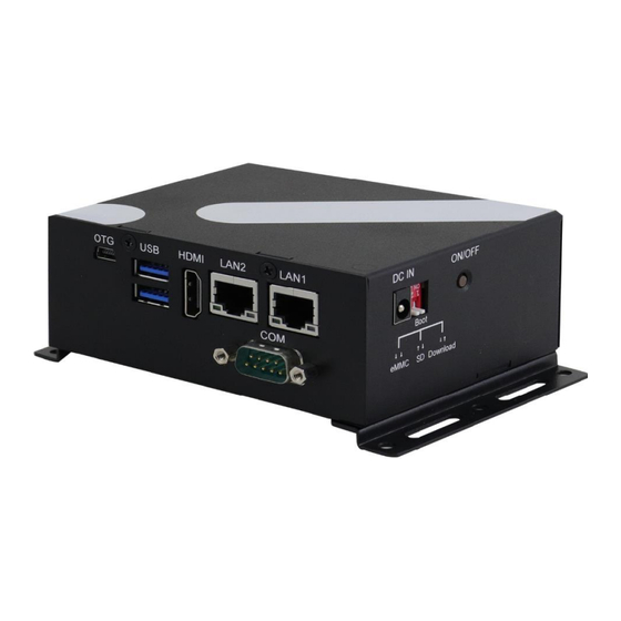
1.5 Product View No. Name No. Name OTG Port Boot Setting USB Ports Power On/Off HDMI Port COM Port GbE LAN Port SD card socket and two screw holes for DIN rail mounting DC-in Power input Antenna holes (reserved) ISR215F User’s Manual... -
Page 13: Dimensions
General Information 1.6 Dimensions Unit: mm ISR215F User’s Manual... - Page 14 General Information ISR215F User’s Manual...
-
Page 15: Chapter 2 Hardware Configuration
Chapter 2 Hardware Configuration This section contains general information about: • Installations • Connectors... -
Page 16: Installations
I/O cover to prevent the extension cable from falling off, should the cable becomes loose. 1. Fasten the hex nut and the washer. Then 2. Apply adhesive around here. install the antenna. Info: The diameter of the nut is around 6.35 mm (0.25”-36UNC). ISR215F User’s Manual... -
Page 17: Mounting Installation
Wall Mounting Installation 1. Turn the device upside down. 2. Prepare at least 4 screws (M3) to Attach the wall-mount kit to the install the device on the wall. device using 4 screws. ISR215F User’s Manual... -
Page 18: Setting The Jumpers
Open When two pins of a jumper are encased in a jumper cap, this jumper is closed, i.e. turned On. When a jumper cap is removed from two jumper pins, this jumper is open, i.e. turned Off. ISR215F User’s Manual... -
Page 19: Connector Locations On Motherboard
Hardware Configuration 2.3 Connector Locations on Motherboard Motherboard: IBR215 ISR215F User’s Manual... -
Page 20: Connectors Quick Reference
DC Power Input P17, CN18 Audio Line-In & Line-Out Connector C Connector CN13 Micro SD Card Slot HDMI Port GbE LAN Port P2,P3 Dual USB 3.0 Type-A Port Mini-USB OTG Port NGFF M.2 3052 Slot SIM Card Socket ISR215F User’s Manual... -
Page 21: Rtc Lithium Cell Connector (Cn1)
Hardware Configuration 2.4.1 RTC Lithium Cell Connector (CN1) Signal Name Signal Name RTC_VCC Ground 2.4.2 RS232 Debug Connector (P16) Assigment DEBUG_RX DEBUG_TX ISR215F User’s Manual... -
Page 22: System On/Off Button (Sw2, Cn17)
Hardware Configuration 2.4.3 System On/Off Button (SW2, CN17) SW2: On/Off Switch CN17: On/Off Signal Header Pin Assigment Pin Assigment Ground ONOFF_B ISR215F User’s Manual... -
Page 23: Running Mode (Sw1)
Hardware Configuration 2.4.4 Running Mode (SW1) Running Mode SW1A SW1B SDHC3(eMMC) SDHC2(SD) USB Download ISR215F User’s Manual... -
Page 24: Lvds Dc Power Input (P17, Cn18)
Hardware Configuration 2.4.5 LVDS DC Power Input (P17, CN18) CN18: DC Input/Output Header Pin Assigment Pin Assigment Ground Ground 12V~24V 12V~24V P17: 12V~24V DC input ISR215F User’s Manual... -
Page 25: Audio Line-In & Line-Out Connector (Cn2)
Hardware Configuration 2.4.6 Audio Line-In & Line-Out Connector (CN2) Signal Name Signal Name Ground Line_Out_R Line_Out_L Ground Line_In_R Line_In_L ISR215F User’s Manual... -
Page 26: I 2 C Connector (Cn13)
Hardware Configuration 2.4.7 C Connector (CN13) Signal Name Signal Name I2C3_SCL I2C3_SDA Ground I2C4_SCL I2C4_SDA Ground ISR215F User’s Manual... -
Page 27: Io Board Port (P18, P19, P20)
CSI_P2_DP3 SD1_DATA0 SD1_DATA1 SD1_CMD SD1_CLK SD1_DATA2 SD1_DATA3 UART1_TXD UART1_RXD UART_TX3/RTS1 UART_RX3/CTS1 VDCDC3_1V8 VDCDC5_3V3 CLKO1_CSI1_MCLK CLKO2_CSI2_MCLK LCD_BL_PWM/GPIO1_01/PWMO1 GPIO1_00/32K_OUT Ground Ground HUB_DP6 HUB_DM6 HUB_DP1 HUB_DM1 HUB_TXDP1 HUB_TXDM1 HUB_RXDP1 HUB_RXDM1 Ground Ground HUB_DP2 HUB_DM2 HUB_TXDP2 HUB_TXDM2 HUB_RXDP2 HUB_RXDM2 USB_PWR_OUT1 USB_PWR_OUT2 ISR215F User’s Manual... - Page 28 Ground LVDS0_TX3_N LVDS0_TX3_P LVDS0_TX2_N LVDS0_TX2_P LVDS0_CLK_N LVDS0_CLK_P LVDS0_TX1_N LVDS0_TX1_P LVDS0_TX0_N LVDS0_TX0_P CSI_P1_DN3 CSI_P1_DP3 CSI_P1_DN2 CSI_P1_DP2 CSI_P1_CKN CSI_P1_CKP CSI_P1_DN1 CSI_P1_DP1 CSI_P1_DN0 CSI_P1_DP0 LVDS1_TX3_N LVDS1_TX3_P LVDS1_TX2_N LVDS1_TX2_P LVDS1_CLK_N LVDS1_CLK_P LVDS1_TX1_N LVDS1_TX1_P LVDS1_TX0_N LVDS1_TX0_P CSI_P2_DN0 CSI_P2_DP0 CSI_P2_DN1 CSI_P2_DP1 CSI_P2_CKN CSI_P2_CKP ISR215F User’s Manual...
-
Page 29: Io Board Jumper & Connectors Quick Reference
LCD Backlight Power Jumper Internal USB3.0 Connector MIPI-CSI Connector CN4,CN5 NGFF M.2 2230 Slot Mini-PCIe Slot Mini-PCIe / NGFF M.2 2230 Jumper SIM Card Socket CAN2.0b CAN1 & CAN2 Connector CN14 Capacitive Touch Screen Interface CN11 IO Expansion Input P20,P21,P22 ISR215F User’s Manual... -
Page 30: Rs-232/422/485 Selection (Sw3)
RS-485 Half Duplex (TX Low-Active) Off On Off On RS-485 Half Duplex (TX High-Active) Off Off Off On RS-422 Full Duplex Off On On Off RS-485 Half Duplex Off On Off Off Shutdown Off Off Off Off ISR215F User’s Manual... -
Page 31: Com Rs-232/422/485 Port (P14)
DSR, Data set ready RXD, Receive data RTS, Request to send TXD, Transmit data CTS, Clear to send DTR, Data terminal ready Refer to the SW3 setting for RS-232/422/485 mode selection. Assignment RS-232 RS-422 RS-485 DATA- DATA+ ISR215F User’s Manual... -
Page 32: Uart1 & Uart3 Connector (Cn12)
Hardware Configuration 2.5.3 (CN12) UART1 & UART3 Connector Assigment Assigment UART3_RXD UART3_TXD UART1_TXD UART1_RXD ISR215F User’s Manual... -
Page 33: Lvds Display Connector (Cn6, Cn7)
LVDS Display Connector (CN6, CN7) CN6: Assigment Assigment LCD0_TX0_P LCD0_TX0_N LCD0_TX1_P LCD0_TX1_N LCD_VDD LCD0_TX3_P LCD0_TX3_N LCD0_TX2_P LCD0_TX2_N LCD0_CLK_P LCD0_CLK_N BTL_PWM LCD_VDD BKLT_VCC BKLT_VCC CN7: Assigment Assigment LCD1_TX0_P LCD1_TX0_N LCD1_TX1_P LCD1_TX1_N LCD_VDD LCD1_TX3_P LCD1_TX3_N LCD1_TX2_P LCD1_TX2_N LCD1_CLK_P LCD1_CLK_N BTL_PWM LCD_VDD BKLT_VCC BKLT_VCC ISR215F User’s Manual... -
Page 34: Lcd Backlight Control Connector (Cn9)
Hardware Configuration 2.5.5 LCD Backlight Control Connector (CN9) Assigment Assigment BKLT_VCC LCD_BKLT_PWM LCD_BKLT_EN ISR215F User’s Manual... -
Page 35: Lvds Power Jumper (P10)
Hardware Configuration 2.5.6 LVDS Power Jumper (P10) Function Pin closed ISR215F User’s Manual... -
Page 36: Lcd Backlight Power Jumper (P11)
Hardware Configuration 2.5.7 LCD Backlight Power Jumper (P11) Function Pin closed ISR215F User’s Manual... -
Page 37: Internal Usb3.0 Connector (Cn3)
Hardware Configuration 2.5.8 Internal USB3.0 Connector (CN3) Assigment Assigment RXDM2 RXDP2 TXDM2 TXDP2 TXDP1 TXDM1 RXDP1 RXDM1 ISR215F User’s Manual... -
Page 38: Mipi-Csi Connector (Cn4,Cn5)
MIPI_CSI1_CKP MIPI_CSI1_CKN MIPI_CSI1_DP0 MIPI_CSI1_DN0 MIPI_CSI1_DP1 MIPI_CSI1_DN1 MIPI_CSI1_DP2 MIPI_CSI1_DN2 MIPI_CSI1_DP3 MIPI_CSI1_DN3 CSI1_SCL CSI1_SDA CSI1_RST_B VDD_2V8 CSI1_PWEN_B VDD_1V8 CSI1_MCLK CN5: Assigment Assigment MIPI_CSI2_CKP MIPI_CSI2_CKN MIPI_CSI2_DP0 MIPI_CSI2_DN0 MIPI_CSI2_DP1 MIPI_CSI2_DN1 MIPI_CSI2_DP2 MIPI_CSI2_DN2 MIPI_CSI2_DP3 MIPI_CSI2_DN3 CSI2_SCL CSI2_SDA CSI2_RST_B VDD_2V8 CSI2_PWEN_B VDD_1V8 CSI2_MCLK ISR215F User’s Manual... -
Page 39: Mini-Pcie / Ngff M.2 2230 Jumper (P5)
Hardware Configuration 2.5.10 Mini-PCIe / NGFF M.2 2230 Jumper (P5) Function Pin closed Mini-PCIe NGFF M.2 2230 ISR215F User’s Manual... -
Page 40: Can Can1 & Can2 Connector(Cn14)
Hardware Configuration 2.5.11 CAN CAN1 & CAN2 Connector(CN14) Assigment Assigment CAN1_H CAN1_L CAN2_H CAN2_L ISR215F User’s Manual... -
Page 41: Capacitive Touch Screen Interface(Cn11)
Hardware Configuration 2.5.12 Capacitive Touch Screen Interface(CN11) Assigment Assigment TP_INT_B TP_RST_B I2C1_SCL I2C1_SDA ISR215F User’s Manual... - Page 42 Hardware Configuration This page is intentionally left blank. ISR215F User’s Manual...
-
Page 43: Chapter 3 Software Setup
Chapter 3 Software Setup This chapter introduces the following setup on the device: (for advanced users only) • Make a recovery SD card • Upgrade firmware through the recovery SD card... -
Page 44: Make A Recovery Sd Card
PC through the mini-USB port (i.e. the P4 connector), and change the boot mode to download mode. 3) Boot IBR215 and flash SD via CMD command “uuu.exe uuu-sdcard.auto” or double click “FW_down-sdcard.bat” (Same way as PCBA update) ISR215F User Manual... -
Page 45: Upgrade Firmware Through The Recovery Sd Card
A> Yocto/Ubuntu: Copy all recovery files into PATH: /USB_flash_disk/hmsupdate/yocto/ B>Android: Copy all recovery files into PATH: /USB_flash_disk/hmsupdate/android/ Plug (step1)SD and (step2)USB flash disk into IBR215 Normal boot IBR215 (SW1 Pin1 OFF), start recovery eMMC automatically. The update information will show on HDMI. ISR215F User Manual... - Page 46 Driver Installation Show “Flashing successfully completed”, then power off and remove recovery SD and USB flash disk. ISR215F User Manual...
-
Page 47: Chapter 4 Bsp Source Guide
Chapter 4 BSP Source Guide This chapter is intended for advanced software engineers to build BSP source. The topics covered in this chapter are as follows: • Preparation • Installing Toolchain • Building release • Installing release to board... -
Page 48: Building Bsp Source
4.1 Building BSP Source 4.1.1 Preparation The recommended minimum Ubuntu version is 18.04 or later. Install necessary packages before building: sudo apt-get install gawk wget git-core diffstat unzip texinfo gcc-multilib \ build-essential chrpath socat cpio python python3 python3-pip python3-pexpect \ xz-utils debianutils iputils-ping python3-git python3-jinja2 libegl1-mesa libsdl1.2-dev \ pylint3 xterm Download toolchain... -
Page 49: Building Release
4.1.2 Building release 4.1.2.1 For Yocto/Ubuntu/Debian cd /home/bsp-folder ./build-bsp-5.4.sh 4.1.2.2 For Android cd /home/bsp-folder source build/envsetup.sh lunch evk_8mp-userdebug make ANDROID_COMPILE_WITH_JACK=false ./imx-make.sh –j4 make –j4 4.1.3 Installing release to board cd /home/bsp-folder for yocto/Ubuntu/debian 1. cp file in release/ to windows 2. - Page 50 This page is intentionally left blank.
-
Page 51: Appendix
Appendix This chapter contains the following information: Onboard Connector Types... -
Page 52: Onboard Connector Types
A. Onboard Connector Types Compatible Mating Function Connector Onboard Type Type for Reference LVDS Display Hirose Hirose P13, P14 Connector DF13E-10DP-1.25V DF13E-10DP-1.25C TechBest UART Connector WT02M-30002-06132 SHR-03V-S-B LVDS Backlight Control TechBest Molex Connector 1024041008 51021-0400 JCTC Audio Line-In & Line- E-Call 11002H00-1P Out Connector...
Need help?
Do you have a question about the ISR215F and is the answer not in the manual?
Questions and answers