Table of Contents
Advertisement
Quick Links
Advertisement
Table of Contents

Related Manuals for IBASE Technology IPPC1501-RE


Summary of Contents for IBASE Technology IPPC1501-RE
- Page 1 IPPC1501-RE User Manual IBASE Technology Inc.
- Page 2 IPPC1501-RE User Manual Revision Release Date V1.0 2014/12/02 Copyright © 2013 IBASE Technology Inc. All Rights Reserved.
- Page 3 IPPC1501-RE User Manual Copyright © 2013 IBASE Technology Inc. All Rights Reserved. No part of this manual, including the products and software described in it, may be reproduced, transmitted, transcribed, stored in a retrieval system, or translated into any language in any form or by any means, except documentation kept by the purchaser for backup purposes, without the express written permission of IBASE Technology INC.
-
Page 4: Table Of Contents
IPPC1501-RE User Manual Table of Contents Setting up your system ....................... iii Care during use ........................iv Acknowledgments ....................... v CHAPTER 1 INTRODUCTION ..........1 1.1 General Description ....................... 1 1.2 System Specification ...................... 2 1.2.1 Hardware Specifications ..................... 2 1.2.2 Dimensions ......................... -
Page 5: Setting Up Your System
IBASE Technology Inc. Safety Information Your IPPC1501-RE is designed and tested to meet the latest standards of safety for information technology equipment. However, to ensure your safety, it is important that you read the following safety instructions. Setting up your system ... -
Page 6: Care During Use
IPPC1501-RE User Manual Care during use Do not walk on the power cord or allow anything to rest on it. Do not spill water or any other liquids on your system. When the system is turned off, a small amount of electrical current still flows. -
Page 7: Acknowledgments
FINTEK is a registered trademark of FINTEK Electronics Corporation. REALTEK is a registered trademark of REALTEK Electronics Corporation. All other product names or trademarks are properties of their respective owners. Copyright © 2013 IBASE Technology Inc. All Rights Reserved. -
Page 9: Chapter 1 Introduction
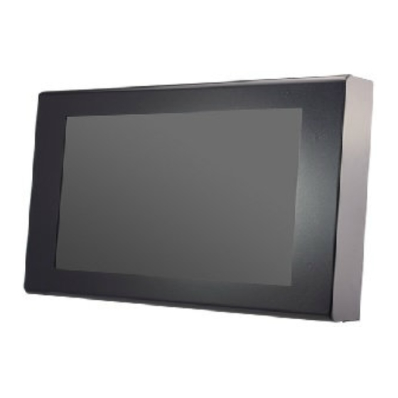
CHAPTER 1 INTRODUCTION 1.1 General Description The IPPC1501-RE is a fanless design panel pc, powered by an Intel Atom processor D2550 with a speed of 1.86GHz. It supports one SO-DIMM slot that can accommodate up to 4GB DDRIII 1066MHz FSB memory. Some of the main features include 4x USB connector, 2x COM port, 1x SATA HDD space support and 12V~24V DC power input. -
Page 10: System Specification
IPPC1501-RE User Manual 1.2 System Specification 1.2.1 Hardware Specifications Model Name IPPC1501-RE System Mainboard IB895 Intel Atom Process D2550 1M Cache, 1.86GHz Chipset Intel NM10 Express Chipset Memory 1 x DDR3 1333 SO-DIMM, maximum 4GB. Default 2GB 1 x DVI-I... -
Page 11: Dimensions
IBASE Technology Inc. 1.2.2 Dimensions IPPC1501-RE Copyright © 2013 IBASE Technology Inc. All Rights Reserved. -
Page 12: I/O View
IPPC1501-RE User Manual 1.2.3 I/O View 1.3 Packing List Part No. Description Terminal block for power input 1 pc Driver CD 1 pc... -
Page 13: Installation
The VESA mount holes are compatible with VESA standard - 75x75 and 100x100 Put your VESA mounting kit on the orange area as shown above. Lock the screws from A to D. Copyright © 2013 IBASE Technology Inc. All Rights Reserved. -
Page 14: Chapter 2 Motherboard Introduction
IPPC1501-RE User Manual CHAPTER 2 MOTHERBOARD INTRODUCTION 2.1 Introduction The IB895 is a 3.5-inch single board computer based on the Intel® Atom Cedarview chipset. The Cedar Trail is a platform that uses the Intel Cedarview-D or Cedarview -M Processor and Intel NM10 Express Chipset family in the desktop platforms. - Page 15 +12V ~ +24V DC-in - i-Smart function (TI MSP430G2433 MCU) Others - AT24C02C EEPROM [SO8 type] via SMbus (Optional) - Windows 7 (32-bit only) OS Support - Linux RoHS Board Size 102mm x 147mm Copyright © 2013 IBASE Technology Inc. All Rights Reserved.
-
Page 16: Board Dimensions
IPPC1501-RE User Manual Board Dimensions... -
Page 17: Installing The Memory
2. Gently push the DDR3 module in an upright position until the clips of the slot close to hold the DDR3 module in place when the DDR3 module touches the bottom of the slot. 3. To remove the DDR3 module, press the clips with both hands. Copyright © 2013 IBASE Technology Inc. All Rights Reserved. -
Page 18: Setting Jumpers
IPPC1501-RE User Manual 2.3 Setting Jumpers Jumpers are used on IB895 to select various settings and features according to your needs and applications. Contact your supplier if you have doubts about the best configuration for your needs. The following lists the connectors on IB895 and their respective functions. - Page 19 JP5: COM1 RS232 RI/+5V/+12V Power Setting Setting Function Pin 1-2 +12V Short/Closed Pin 3-4 Short/Closed Pin 5-6 Short/Closed JP6: LVDS Panel Power Selection Setting Panel Voltage Pin 1-2 3.3V (default) Short/Closed Pin 2-3 Short/Closed Copyright © 2013 IBASE Technology Inc. All Rights Reserved.
- Page 20 IPPC1501-RE User Manual JP7: BL_ADJ_LEVEL Setting (PWM Mode) Setting Voltage Open 3.3V (default) Close JP8: Factory use only SW1: LVDS Panel Type Setting SW1-4 SW1-3 SW1-2 SW1-1 Panel Type 800*600 18bit 1ch 1024*768 18bit 1ch 1024*768 24bit 1ch 1280*768 18bit 1ch...
-
Page 21: Connectors
2.4 Connectors Connector Locations on IB895 CN4, CN5: Gigabit LAN (Intel 82583V) This RJ45 LAN connector (CN4 only) features for EUP LAN wakeup. CN6: USB 1/2 Connector CN7: VGA DVI-I Connector Copyright © 2013 IBASE Technology Inc. All Rights Reserved. - Page 22 IPPC1501-RE User Manual CN8: DB9 Connector (COM1) is a DB-9 connector. Signal Name Pin # Pin # Signal Name DCD, Data carrier detect DSR, Data set ready RXD, Receive data RTS, Request to send TXD, Transmit data CTS, Clear to send...
- Page 23 Signal Name Ground Ground +12V J4: Debug 80 Port Connector (factory use only) J5: Digital I/O Connector Signal Name Signal Name OUT3 OUT1 OUT2 OUT0 J6: SPI Flash Connector (factory use only) Copyright © 2013 IBASE Technology Inc. All Rights Reserved.
- Page 24 IPPC1501-RE User Manual J7: Keyboard & Mouse Connector (DF11 Connector) Pin # Pin # Signal Name Signal Name KBDA KBCL Ground Ground J8: DDR3 SO-DIMM Socket J9: Mini PCIE Connector(Support mSATA) J9 also supports mSATA. However, when J9 is used for mSATA, then CN3 SATA port cannot be used.
- Page 25 Not Used J17: Mini PCIE Connector J18: Audio Connector (DF11 Connector) Signal Name Signal Name Pin # Pin # LINEOUT_R LINEOUT_L Ground JD_FRONT LINEIN_R LINEIN_L Ground JD_LINEIN MIC-R MIC_L Ground JD_MIC1 Copyright © 2013 IBASE Technology Inc. All Rights Reserved.
- Page 26 IPPC1501-RE User Manual J22: Amplify Connector Pin # Signal Name OUTL+ OUTL- OUTR- OUTR+ J23: LVDS EEPROM Flash Connector (factory use only) CH1, CH2: LVDS Connectors Signal Name Pin # Pin # Signal Name ENABLE LCD_PWR CLK+ CLK- LD2+ LD2-...
- Page 27 The reset switch allows the user to reset the system without turning the main power switch off and then on again. Orientation is not required when making a connection to this header. Copyright © 2013 IBASE Technology Inc. All Rights Reserved.
-
Page 28: Chapter 3 Bios Setup
IPPC1501-RE User Manual CHAPTER 3 BIOS SETUP 3.1 BIOS Introduction The BIOS (Basic Input/Output System) installed in your computer system’s ROM supports Intel processors. The BIOS provides critical low-level support for a standard device such as disk drives, serial ports and parallel ports. It also password protection as well as special support for detailed fine-tuning of the chipset controlling the entire system. - Page 29 System Date Set the Date. Use Tab to switch between Data elements. System Time Set the Time. Use Tab to switch between Data elements. Copyright © 2013 IBASE Technology Inc. All Rights Reserved.
-
Page 30: Advanced Settings
IPPC1501-RE User Manual 3.3 Advanced Settings This section allows you to configure and improve your system and allows you to set up some system features according to your preference. Aptio Setup Utility Main Advanced Chipset Boot Security Save & Exit... - Page 31 Value to be programmed into PCI Latency Timer Register. VGA Palette Snoop Enables or Disables VGA Palette Registers Snooping. PERR# Generation Enables or Disables PCI Device to Generate PERR#. SERR# Generation Enables or Disables PCI Device to Generate SERR#. Copyright © 2013 IBASE Technology Inc. All Rights Reserved.
- Page 32 IPPC1501-RE User Manual ACPI Settings Aptio Setup Utility Advanced Main Chipset Boot Security Save & Exit ACPI Settings Enable ACPI Auto Configuration Disabled → ←Select Screen ↑↓ Select Item Enter: Select +- Change Opt F1: General Help F2: Previous Values F3: Optimized Default F4: Save &...
- Page 33 F2: Previous Values F3: Optimized Default F4: Save & EXIT ESC: Exit Wake on Ring The options are Disabled and Enabled. Wake on PCIE PME The options are Disabled and Enabled. Copyright © 2013 IBASE Technology Inc. All Rights Reserved.
- Page 34 IPPC1501-RE User Manual CPU Configuration This section shows the CPU configuration parameters. Aptio Setup Utility Advanced Main Chipset Boot Security Save & Exit CPU Configuration Processor Type Intel(R) Atom(TM) CPU EMT64 Supported Processor Speed 1865 MHz System Bus Speed 533 MHz...
- Page 35 This field sets the system power status whether on or off when power returns to the system from a power failure situation. Schedule Slot None / Power On / Power On/Off – Setup the hour/minute for system power on Copyright © 2013 IBASE Technology Inc. All Rights Reserved.
- Page 36 IPPC1501-RE User Manual IDE Configuration Aptio Setup Utility Advanced Main Chipset Boot Security Save & Exit SATA Port0 Not Present SATA Port1 Not Present → ←Select Screen ↑↓ Select Item SATA Controller(s) Enabled Enter: Select +- Change Opt F1: General Help...
- Page 37 Maximum time the device will take before it properly reports itself to the Host Controller. ‘Auto’ uses default value: for a Root port it is 100ms, for a Hub port the delay is taken from Hub descriptor. Copyright © 2013 IBASE Technology Inc. All Rights Reserved.
- Page 38 IPPC1501-RE User Manual Super IO Configuration Aptio Setup Utility Advanced Main Chipset Boot Security Save & Exit W83627UHG Super IO Configuration → ←Select Screen Super IO Chip Winbond W83627UHG ↑↓ Select Item Enter: Select ► W83627UHG Serial Port 0 Configuration...
- Page 39 Save & Exit PPM Configuration → ←Select Screen ↑↓ Select Item Enter: Select +- Change Opt F1: General Help EIST Enabled F2: Previous Values F3: Optimized Default F4: Save & EXIT ESC: Exit Copyright © 2013 IBASE Technology Inc. All Rights Reserved.
-
Page 40: Chipset Settings
IPPC1501-RE User Manual 3.4 Chipset Settings This section allows you to configure and improve your system and allows you to set up some system features according to your preference. Aptio Setup Utility Advanced Main Chipset Boot Security Save & Exit ►... - Page 41 Max TOLUD Dynamic F2: Previous Values F3: Optimized Default F4: Save & EXIT ESC: Exit MRC Fast Boot The options are Disabled and Enabled. Max TOLUD The default setting is Dynamic. Copyright © 2013 IBASE Technology Inc. All Rights Reserved.
- Page 42 IPPC1501-RE User Manual Intel IGD Configuration Aptio Setup Utility Chipset Main Advanced Boot Security Save & Exit → ←Select Screen Intel IGD Configuration ↑↓ Select Item Enter: Select IGFX-Boot Type VBIOS Default +- Change Opt F1: General Help LVDS Back Light Control...
- Page 43 ↑↓ Select Item ASPM L0s Root Port Only Enter: Select +- Change Opt F1: General Help ASPM L1 Enabled F2: Previous Values F3: Optimized Default F4: Save & EXIT ESC: Exit Copyright © 2013 IBASE Technology Inc. All Rights Reserved.
- Page 44 IPPC1501-RE User Manual PCI Express Root Port1 Aptio Setup Utility Chipset Main Advanced Boot Security Save & Exit PCI Express Port 0 Auto Port 0 IOxAPIC Disabled Automatic ASPM Manual → ←Select Screen ASPM L0s Root Port Only ↑↓ Select Item...
- Page 45 ↑↓ Select Item Enter: Select Automatic ASPM Manual +- Change Opt F1: General Help ASPM L0s Disabled F2: Previous Values F3: Optimized Default ASPM L1 Disabled F4: Save & EXIT ESC: Exit Copyright © 2013 IBASE Technology Inc. All Rights Reserved.
- Page 46 IPPC1501-RE User Manual Boot Settings Aptio Setup Utility Boot Main Advanced Chipset Security Save & Exit Boot Configuration Setup Prompt Timeout Bootup NumLock State Quiet Boot Disabled Fast Boot Disabled CSM16 Module Version 07.68 → ←Select Screen ↑↓ Select Item...
-
Page 47: Security Settings
+- Change Opt F1: General Help Administrator Password F2: Previous Values F3: Optimized Default User Password F4: Save & EXIT ESC: Exit Administrator Password Set Setup Administrator Password. User Password Set User Password. Copyright © 2013 IBASE Technology Inc. All Rights Reserved. -
Page 48: Save & Exit Settings
IPPC1501-RE User Manual 3.6 Save & Exit Settings Aptio Setup Utility Advanced Main Chipset Boot Security Save & Exit Save Changes and Exit Discard Changes and Exit Save Changes and Reset Discard Changes and Reset Save Options → ←Select Screen ↑↓... -
Page 49: Chapter 4 Drivers Installation
5. On the Readme File Information screen, click Next to continue the installation. 6. The Setup process is now complete. Click Finish to restart the computer and for changes to take effect. Copyright © 2013 IBASE Technology Inc. All Rights Reserved. -
Page 50: Vga Drivers Installation
IPPC1501-RE User Manual 4.2 VGA Drivers Installation IMPORTANT NOTE: After installing the graphics driver, the default display is still LVDS. Both VGA/CRT and DVI will only be extended displays. To switch to any of these displays, use the hot key: For VGA –... -
Page 51: Realtek Hd Audio Driver Installation
1. Click Realtek High Definition Audio Driver. 2. On the Welcome to the InstallShield Wizard screen, click Next to proceed with and complete the installation process. 3. Restart the computer when prompted. Copyright © 2013 IBASE Technology Inc. All Rights Reserved. -
Page 52: Lan Drivers Installation
IPPC1501-RE User Manual 4.4 LAN Drivers Installation 1. Insert the CD that comes with the board. Click LAN Card and then Intel(R) LAN Controller Drivers. 2. Click Intel(R) Gigabit Ethernet Drivers. 3. In the Welcome screen, click Next. 4. In the License Agreement screen, click I accept the terms in license agreement and Next to accept the software license agreement and proceed with the installation process. -
Page 53: Appendix
Programmable interrupt controller 00B4-00B5 Programmable interrupt controller 00B8-00B9 Programmable interrupt controller 00BC-00BD Programmable interrupt controller 00C0-00DF Direct memory access controller 00F0-00F0 Numeric data processor 02E8-02EF Communications Port (COM4) 02F8-02FF Communications Port (COM2) Copyright © 2013 IBASE Technology Inc. All Rights Reserved. - Page 54 IPPC1501-RE User Manual Address Device Description 03B0-03BB Intel(R) Graphics Media Accelerator 3600 Series 03C0-03DF Intel(R) Graphics Media Accelerator 3600 Series 03E8-03EF Communications Port (COM3) 03F8-03FF Communications Port (COM1) 04D0-04D1 Programmable interrupt controller 0D00-FFFF PCI bus D000-DFFF Intel(R) N10/ICH7 Family PCI Express Root Port - 27D2...
-
Page 55: Interrupt Request Lines (Irq)
Intel(R) 82583V Gigabit Network Connection #2 IRQ 4294967292 Intel(R) Graphics Media Accelerator 3600 Series IRQ 4294967293 Intel(R) N10/ICH7 Family PCI Express Root Port - 27D2 IRQ 4294967294 Intel(R) N10/ICH7 Family PCI Express Root Port - 27D0 Copyright © 2013 IBASE Technology Inc. All Rights Reserved. - Page 56 IPPC1501-RE User Manual C. Digital I/O Sample Code File of the W627UHG.H //--------------------------------------------------------------------------- // THIS CODE AND INFORMATION IS PROVIDED "AS IS" WITHOUT WARRANTY OF ANY // KIND, EITHER EXPRESSED OR IMPLIED, INCLUDING BUT NOT LIMITED TO THE // IMPLIED WARRANTIES OF MERCHANTABILITY AND/OR FITNESS FOR A PARTICULAR // PURPOSE.
- Page 57 = Get_W627UHG_Reg(0x20); if (ucDid == 0xA2) //W83627UHG?? goto Init_Finish; W627UHG_BASE = 0x2E; result = W627UHG_BASE; ucDid = Get_W627UHG_Reg(0x20); if (ucDid == 0xA2) //W83627UHG?? goto Init_Finish; W627UHG_BASE = 0x00; result = W627UHG_BASE; Copyright © 2013 IBASE Technology Inc. All Rights Reserved.
- Page 58 IPPC1501-RE User Manual Init_Finish: return (result); //--------------------------------------------------------------------------- void Unlock_W627UHG (void) outportb(W627UHG_INDEX_PORT, W627UHG_UNLOCK); outportb(W627UHG_INDEX_PORT, W627UHG_UNLOCK); //--------------------------------------------------------------------------- void Lock_W627UHG (void) outportb(W627UHG_INDEX_PORT, W627UHG_LOCK); //--------------------------------------------------------------------------- void Set_W627UHG_LD( unsigned char LD)
- Page 59 Set_W627UHG_Reg( unsigned char REG, unsigned char DATA) Unlock_W627UHG(); outportb(W627UHG_INDEX_PORT, REG); outportb(W627UHG_DATA_PORT, DATA); Lock_W627UHG(); //--------------------------------------------------------------------------- unsigned char Get_W627UHG_Reg(unsigned char REG) unsigned char Result; Unlock_W627UHG(); outportb(W627UHG_INDEX_PORT, REG); Result = inportb(W627UHG_DATA_PORT); Lock_W627UHG(); return Result; //--------------------------------------------------------------------------- Copyright © 2013 IBASE Technology Inc. All Rights Reserved.
-
Page 60: Digital I/O Sample Code
IPPC1501-RE User Manual File of the MAIN.CPP //--------------------------------------------------------------------------- // THIS CODE AND INFORMATION IS PROVIDED "AS IS" WITHOUT WARRANTY OF ANY // KIND, EITHER EXPRESSED OR IMPLIED, INCLUDING BUT NOT LIMITED TO THE // IMPLIED WARRANTIES OF MERCHANTABILITY AND/OR FITNESS FOR A PARTICULAR // PURPOSE. - Page 61 IBASE Technology Inc. printf("Current DIO direction = 0x%X\n", Dio5GetDirection()); printf("Current DIO status = 0x%X\n", Dio5GetInput()); printf("Set DIO output to high\n"); Dio5SetOutput(0x0F); printf("Set DIO output to low\n"); Dio5SetOutput(0x00); return 0; Copyright © 2013 IBASE Technology Inc. All Rights Reserved.
- Page 62 IPPC1501-RE User Manual //--------------------------------------------------------------------------- void Dio5Initial(void) unsigned char ucBuf; Set_W627UHG_LD(0x08); //switch to logic device 8 //enable the GP5 group ucBuf = Get_W627UHG_Reg(0x30); ucBuf |= 0x02; Set_W627UHG_Reg(0x30, ucBuf); //--------------------------------------------------------------------------- void Dio5SetOutput(unsigned char NewData) Set_W627UHG_LD(0x08); //switch to logic device 8 Set_W627UHG_Reg(0xE1, NewData);...
- Page 63 IBASE Technology Inc. Set_W627UHG_LD(0x08); //switch to logic device 8 result = Get_W627UHG_Reg(0xE0); return (result); //--------------------------------------------------------------------------- Copyright © 2013 IBASE Technology Inc. All Rights Reserved.
- Page 64 IPPC1501-RE User Manual D. Watchdog Timer Configuration The WDT is used to generate a variety of output signals after a user programmable count. The WDT is suitable for use in the prevention of system lock-up, such as when software becomes trapped in a deadlock.
- Page 65 IBASE Technology Inc. W627UHG_BASE = 0x2E; result = W627UHG_BASE; ucDid = Get_W627UHG_Reg(0x20); if (ucDid == 0xA2) //W83627UHG?? goto Init_Finish; } W627UHG_BASE = 0x00; result = W627UHG_BASE; Copyright © 2013 IBASE Technology Inc. All Rights Reserved.
- Page 66 IPPC1501-RE User Manual Init_Finish: return (result); //--------------------------------------------------------------------------- void Unlock_W627UHG (void) outportb(W627UHG_INDEX_PORT, W627UHG_UNLOCK); outportb(W627UHG_INDEX_PORT, W627UHG_UNLOCK); //--------------------------------------------------------------------------- void Lock_W627UHG (void) outportb(W627UHG_INDEX_PORT, W627UHG_LOCK); //--------------------------------------------------------------------------- void Set_W627UHG_LD( unsigned char LD) Unlock_W627UHG(); outportb(W627UHG_INDEX_PORT, W627UHG_REG_LD); outportb(W627UHG_DATA_PORT, LD); Lock_W627UHG(); //--------------------------------------------------------------------------- void Set_W627UHG_Reg( unsigned char REG, unsigned char DATA) Unlock_W627UHG();...
- Page 67 W627UHG_REG_LD 0x07 //--------------------------------------------------------------------------- #define W627UHG_UNLOCK 0x87 #define W627UHG_LOCK 0xAA //--------------------------------------------------------------------------- unsigned int Init_W627UHG(void); void Set_W627UHG_LD( unsigned char); void Set_W627UHG_Reg( unsigned char, unsigned char); unsigned char Get_W627UHG_Reg( unsigned char); //--------------------------------------------------------------------------- #endif //__W627UHG_H Copyright © 2013 IBASE Technology Inc. All Rights Reserved.
-
Page 68: Watchdog Timer Configuration
IPPC1501-RE User Manual File of the MAIN.CPP //--------------------------------------------------------------------------- // THIS CODE AND INFORMATION IS PROVIDED "AS IS" WITHOUT WARRANTY OF ANY // KIND, EITHER EXPRESSED OR IMPLIED, INCLUDING BUT NOT LIMITED TO THE // IMPLIED WARRANTIES OF MERCHANTABILITY AND/OR FITNESS FOR A PARTICULAR // PURPOSE. - Page 69 IBASE Technology Inc. return 0; //--------------------------------------------------------------------------- void WDTInitial(void) unsigned char bBuf; Set_W627UHG_LD(0x08); ......//switch to logic device 8 bBuf = Get_W627UHG_Reg(0x30); bBuf &= (~0x01); Set_W627UHG_Reg(0x30, bBuf); ......//Enable WDTO //--------------------------------------------------------------------------- void WDTEnable(unsigned char NewInterval) Copyright © 2013 IBASE Technology Inc. All Rights Reserved.
- Page 70 IPPC1501-RE User Manual unsigned char bBuf; Set_W627UHG_LD(0x08); ......//switch to logic device 8 Set_W627UHG_Reg(0x30, 0x01); ......//enable timer bBuf = Get_W627UHG_Reg(0xF5); bBuf &= (~0x08); Set_W627UHG_Reg(0xF5, bBuf); ....//count mode is second Set_W627UHG_Reg(0xF6, NewInterval); ......//set timer //--------------------------------------------------------------------------- void WDTDisable(void) Set_W627UHG_LD(0x08); ..............Set_W627UHG_Reg(0xF6, 0x00); ....//clear watchdog timer Set_W627UHG_Reg(0x30, 0x00);...
Need help?
Do you have a question about the IPPC1501-RE and is the answer not in the manual?
Questions and answers