
Related Manuals for IBASE Technology ISR101


Summary of Contents for IBASE Technology ISR101
- Page 1 ISR101 Ruggedized Embedded System ® ® with NXP ARM Cortex A9 i.MX6 Dual-Lite SoC User’s Manual Version 1.0 (Aug. 2018)
- Page 2 No part of this publication may be reproduced, copied, stored in a retrieval system, translated into any language or transmitted in any form or by any means, electronic, mechanical, photocopying, or otherwise, without the prior written consent of IBASE Technology, Inc. (hereinafter referred to as “IBASE”).
-
Page 3: Compliance
0.1% by weight (1000 ppm) except for cadmium, limited to 0.01% by weight (100 ppm). • Lead (Pb) • Mercury (Hg) • Cadmium (Cd) • Hexavalent chromium (Cr6+) • Polybrominated biphenyls (PBB) • Polybrominated diphenyl ether (PBDE) ISR101 User Manual... -
Page 4: Important Safety Information
Do not try to repair, disassemble, or make modifications to the device. Doing so will void the warranty and may result in damage to the product or personal injury. CAUTION Replace only with the same or equivalent type recommended by the manufacturer. Dispose of used batteries by observing local regulations. ISR101 User Manual... -
Page 5: Warranty Policy
The arrangement of the peripherals • Software used (such as OS and application software) 3. If repair service is required, please download the RMA form at http://www.ibase.com.tw/english/Supports/RMAService/. Fill out the form and contact your distributor or sales representative. ISR101 User Manual... -
Page 6: Table Of Contents
RTC Lithium Cell Connector (P2) ......... 14 2.4.3 COM RS-232/422/485 Port (P10) ......... 15 2.4.4 USB Hub Connector (P13) ........... 16 2.4.5 Digital (GPIO) Connector (P18) ..........16 Chapter 3 Software Setup ..............17 Make a Recovery MicroSD Card ............18 ISR101 User Manual... - Page 7 How to Use Watchdog in Linux ............. 25 eMMC Test ................... 26 USB (flash disk) Test ................27 MicroSD Card Test................28 RS-232 Test ..................29 RS-485 Test ..................30 Ethernet Test ..................31 HDMI Test ..................... 32 ISR101 User Manual...
-
Page 8: Chapter 1 General Information
Chapter 1 General Information The information provided in this chapter includes: • Features • Packing List • Optional Accessories • Specifications • Overview • Dimensions... -
Page 9: Introduction
1.1 Introduction ® ® ISR101 is an ARM -based embedded system with NXP Cortex i.MX6 A9 processor. The device offers 2D, 3D graphics and multimedia accelerations while it also features numerous peripherals that are well suited for industrial applications, including RS-232/422/485, COM, GPIO, USB, USB OTG, LAN, HDMI for a full HD display and M.2 E2230 for wireless connectivity. -
Page 10: Specifications
2 x USB 2.0 Type A • 1 x USB OTG via mini-USB Type B Serial 1 x COM RS-232/422/485 port MicroSD 1 x MicroSD socket (max.104 MB/s) Digital IO 8 In / Out Expansion 1 x M.2 E-key (2230) Slots ISR101 User Manual... - Page 11 Environment Operating 0 ~ 60 °C (32 ~ 140 °F) Temperature Relative 10 ~ 90 %, non-condensing Humidity All specifications are subject to change without prior notice. ISR101 User Manual...
-
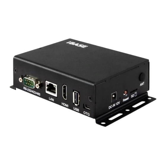
Page 12: Overview
I/O View Top View No. Name No. Name COM RS-232/422/485 Port Reset Button GbE LAN Port MicroSD Card Slot HDMI Port Antenna Hole USB 2.0 Ports GPIO Port USB OTG Port DIN Rail Mounting Holes DC Jack ISR101 User Manual... -
Page 13: Dimensions
DIN Rail Mounting View (Optional) 1.7 Dimensions Unit: mm ISR101 User Manual... -
Page 14: Chapter 2 Hardware Configuration
Chapter 2 Hardware Configuration This section contains general information about: • Installations • Jumper and connectors... -
Page 15: Installations
1. Align the keys of the M.2 card with that of the M.2 slot, and insert the card slantwise. 2. Push the M.2 card downwards as shown in the picture below, and fix it onto the brass standoff with a screw. ISR101 User Manual... -
Page 16: Wifi / 3G / 4G Antenna Installation
Wall Mounting Installation 1. Turn your device upside down. 2. Prepare at least 4 screws (M3) to Attach the wall-mount kit to the install the device on the wall. device and secure with the supplied 4 screws. ISR101 User Manual... -
Page 17: Com Rs-232/422/485 Port
TXD, Transmit data CTS, Clear to send DTR, Data terminal ready Ground Assignment RS-232 RS-422 RS-485 DATA- DATA+ Ground Ground Ground 2.1.5 GPIO Port ➔ Signal Name Signal Name DIO1 DIO5 DIO2 DIO6 DIO3 DIO7 DIO4 DIO8 Ground ISR101 User Manual... -
Page 18: Setting The Jumpers
1 2 3 When two pins of a jumper are encased in a jumper cap, this jumper is closed, i.e. turned On. When a jumper cap is removed from two jumper pins, this jumper is open, i.e. turned Off. ISR101 User Manual... -
Page 19: Jumper & Connector Locations On Motherboard
2.3 Jumper & Connector Locations on Motherboard Motherboard: IBR115 ISR101 User Manual... -
Page 20: Jumper & Connectors Quick Reference
MicroSD Card Connector GbE LAN Port USB 2.0 Type A Port Mini-USB OTG Port NGFF M.2 Slot HDMI Port Factory Use Only SW1, P11, P19 Jumpers: Function Connector Name Page LVDS Power Setting LVDS Backlight Power Setting ISR101 User Manual... -
Page 21: Rs-232/422/485 Selection (Sw3)
Panel Type RS-422 Full Duplex Pure RS232 (3T/5R) RS-485 Half Duplex (TX Low-Active) RS-485 Half Duplex (TX High-Active) RS-422 Full Duplex RS-485 Half Duplex Shutdown (Default) 2.4.2 RTC Lithium Cell Connector (P2) Signal Name Signal Name RTC_VCC Ground ISR101 User Manual... -
Page 22: Com Rs-232/422/485 Port (P10)
Signal Name DCD, Data carrier detect DSR, Data set ready RXD, Receive data RTS, Request to send TXD, Transmit data CTS, Clear to send DTR, Data terminal ready Ground Assignment RS-232 RS-422 RS-485 DATA- DATA+ Ground Ground Ground ISR101 User Manual... -
Page 23: Usb Hub Connector (P13)
2.4.4 USB Hub Connector (P13) Signal Name Signal Name Ground USB1_DP USB2_POWER USB1_DM USB2_DM USB1_POWER USB2_DP Ground 2.4.5 Digital (GPIO) Connector (P18) Signal Name Signal Name 3.3V DIO5 DIO1 DIO6 DIO2 DIO7 DIO3 DIO8 DIO4 Ground ISR101 User Manual... -
Page 24: Chapter 3 Software Setup
Chapter 3 Software Setup This chapter introduces the following setup on the device: • Make a recovery microSD card (for advanced users only) • Display parameter setting in kernel... -
Page 25: Make A Recovery Microsd Card
3.1 Make a Recovery MicroSD Card Note: This is for advanced users who has IBASE standard image file only. Basically, ISR101 is preloaded with O.S (Android / Linux) into eMMC by default. Connect the TFT-LCD with ISR101 (or HDMI), and 12V power directly. - Page 26 32 976762584 sdc 3880960 sdd 512000 sdd1 3367936 sdd2 6-D. Compare 6-A and 6-C, and get sdd. 7. Run make_card script. ./make_emmc_sd.sh /dev/sdd 20150814-111827 8. The string "file system create done" means success. 9. Pull out the microSD card. ISR101 User Manual...
-
Page 27: Upgrade Firmware Through The Recovery Microsd Card
3.1.2 Upgrade Firmware through the Recovery MicroSD Card 1. Insert the microSD card into ISR101. 2. Insert power to boot up and upgrade the firmware via the microSD card. 3. It takes about 15 minutes. After 10 minutes, the screen goes into sleep. -
Page 28: Chapter 4 Bsp Source Guide
Chapter 4 BSP Source Guide This chapter is dedicated for advanced software engineers only to build BSP source. The topics covered in this chapter are as follows: • Preparation • Installing Toolchain • Building U-Boot • Building Kernel • Building RAMdisk Image (Optional) •... -
Page 29: Building Bsp Source
2. Decompress the ISR101 source file ISR101.tar.xz into "/home/" folder. 4.1.2 Installing Toolchain Decompress Toolchain poky.tar into directory "/opt". 4.1.3... -
Page 30: Building Ramdisk Image (Optional)
BSP Source Guide 4.1.5 Building RAMdisk Image (Optional) 1. Enter ISR101. cd /home/ISR101 2. Running the script below. ./build.sh ISR101 3. See the image in the "release" directory. ls release/ISR101-20170519-030011/ rootfs.tar.bz2 u-boot-imx6dlsabresd.imx zImage zImage-imx6dl- sabresd.dtb 4.1.6 Install Linux to MicroSD Card 1. -
Page 31: Appendix
Appendix This section provides the information of reference code. -
Page 32: How To Use Gpio In Linux
//open watchdog device fd = open("/dev/watchdog", O_WRONLY); //get watchdog support ioctl(fd, WDIOC_GETSUPPORT, &ident); //get watchdog status ioctl(fd, WDIOC_GETSTATUS, &status); //get watchdog timeout ioctl(fd, WDIOC_GETTIMEOUT, &timeout_val); //set watchdog timeout ioctl(fd, WDIOC_SETTIMEOUT, &timeout_val); //feed dog ioctl(fd, WDIOC_KEEPALIVE, &dummy); ISR101 User Manual... -
Page 33: Emmc Test
#read data2, and compare with data1 cmp $MOUNT_POINT_STR/data2 /tmp/data1 • eMMC speed test MOUNT_POINT_STR="/var" #get emmc write speed" time dd if=/dev/urandom of=$MOUNT_POINT_STR/test bs=1024k count=10 # clean caches echo 3 > /proc/sys/vm/drop_caches #get emmc read speed" time dd if=$MOUNT_POINT_STR/test of=/dev/null bs=1024k count=10 ISR101 User Manual... -
Page 34: Usb (Flash Disk) Test
Appendix D. USB (flash disk) Test Insert the USB flash disk then assure it is in ISR101 device list. Note: This operation may damage the data stored in the USB flash disk. Before starting the test, make sure there is no critical data in the eMMC flash being used. -
Page 35: Microsd Card Test
MicroSD Card Test When ISR101 is booted from eMMC, microSD card is “/dev/mmcblk1” and able to see by “ls /dev/mmcblk1*” command: /dev/mmcblk1 /dev/mmcblk1p2 /dev/mmcblk1p4 /dev/mmcblk1p5 /dev/mmcblk1p6 When booting from microSD card, replace test pattern “/dev/mmcblk1” to “/dev/mmcblk0”. Note: This operation may damage the data stored the microSD card. Before starting the test, make sure there is no critical data in the eMMC flash being used. -
Page 36: Rs-232 Test
&= ~CSIZE; options.c_lflag &= ~(ICANON | ECHO | ECHOE | ISIG); /*Input*/ options.c_oflag &= ~OPOST; /*Output*/ //options.c_cc options.c_cc[VTIME] = 150; options.c_cc[VMIN] = 0; #set parity tcsetattr(fd, TCSANOW, &options) //write ttymxc1 write(fd, write_buf, sizeof(write_buf)); //read ttymxc1 read(fd, read_buf, sizeof(read_buf))) ISR101 User Manual... -
Page 37: Rs-485 Test
&= ~CSIZE; options.c_lflag &= ~(ICANON | ECHO | ECHOE | ISIG); /*Input*/ options.c_oflag &= ~OPOST; /*Output*/ //options.c_cc options.c_cc[VTIME] = 150; options.c_cc[VMIN] = 0; #set parity tcsetattr(fd, TCSANOW, &options) //write ttymxc1 write(fd, write_buf, sizeof(write_buf)); //read ttymxc1 read(fd, read_buf, sizeof(read_buf))) ISR101 User Manual... -
Page 38: Ethernet Test
-c 192.168.1.123 -i 1 -t 20 -w 32M -P 4 • Ethernet UDP test #server 192.168.1.123 run command “iperf3 -s” #communicate with server 192.168.1.123 in udp mode by iperf3 iperf3 -c $SERVER_IP -u -i 1 -b 200M ISR101 User Manual... -
Page 39: Hdmi Test
*(fbp + location + 1) = color_g; *(fbp + location + 2) = color_r; //close framebuffer fd close(framebuffer_fd); • HDMI audio test #enable hdmi audio echo 0 > /sys/class/graphics/fb2/blank #play wav file by hdmi audio aplay /home/root/testscript/hdmi/1K.wav -D plughw:0,0 ISR101 User Manual...
Need help?
Do you have a question about the ISR101 and is the answer not in the manual?
Questions and answers