Table of Contents
Advertisement
Quick Links
Advertisement
Table of Contents

Subscribe to Our Youtube Channel
Related Manuals for IBASE Technology IDOOH-210-IR


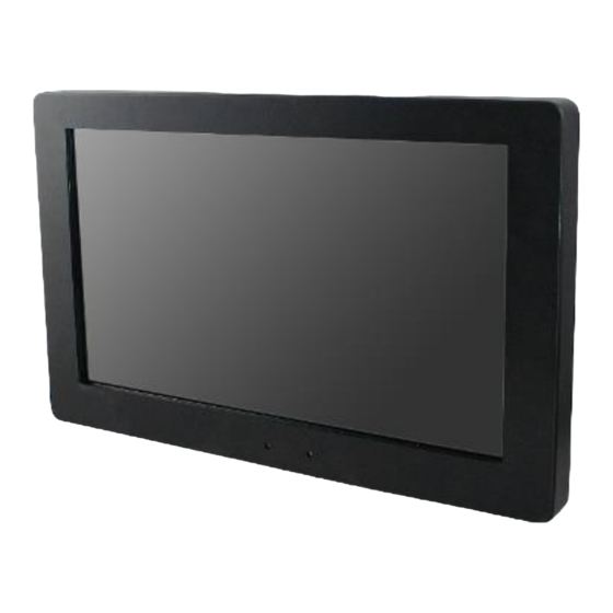
Summary of Contents for IBASE Technology IDOOH-210-IR
- Page 1 IDOOH-210-IR User Manual IBASE Technology Inc.
- Page 2 IDOOH-210-IR User Manual Revision Release Date 2015/07/01 Copyright © 2013 IBASE Technology Inc. All Rights Reserved.
- Page 3 IDOOH-210-IR User Manual Copyright © 2013 IBASE Technology Inc. All Rights Reserved. No part of this manual, including the products and software described in it, may be reproduced, transmitted, transcribed, stored in a retrieval system, or translated into any language in any form or by any means, except documentation kept by the purchaser for backup purposes, without the express written permission of IBASE Technology INC.
-
Page 4: Table Of Contents
IDOOH-210-IR User Manual Table of Contents Safety Information ....................iii Setting up your system ....................iii Care during use ......................iv Acknowledgments ......................v CHAPTER 1 INTRODUCTION ................... 1 1.1 General Description ....................1 1.2 System Specification ....................2 1.2.1 Hardware Specifications ..................2 1.2.2 Dimensions ...................... -
Page 5: Safety Information
STORAGE TEMPERATURE MAY GO BELOW -40° C OR ABOVE 60° C. THIS COULD DAMAGE THE EQUIPMENT. THE EQUIPMENT SHOULD BE IN A CONTROLLED ENVIRONMENT. *With 1120W/m² solar energy: 44 °C or with 900W/m² solar energy: 50 °C Copyright © 2013 IBASE Technology Inc. All Rights Reserved. -
Page 6: Care During Use
IDOOH-210-IR User Manual Care during use Do not walk on the power cord or allow anything to rest on it. Do not spill water or any other liquids on your system. When the system is turned off, a small amount of electrical current still flows. -
Page 7: Acknowledgments
FINTEK is a registered trademark of FINTEK Electronics Corporation. REALTEK is a registered trademark of REALTEK Electronics Corporation. All other product names or trademarks are properties of their respective owners. Copyright © 2013 IBASE Technology Inc. All Rights Reserved. -
Page 9: Chapter 1 Introduction
E3800 series processor to provide high computing performance and low power consumption The IDOOH-210-IR operates silently and reliably in harsh environments. It comes with two SODIMM slots to accommodate up to 8GB of DDR3L 1333MHz system memory and one 2.5” SATA SSD for data storage. It is provided with two Gigabit Ethernet, one RS-232/422/485 port. -
Page 10: System Specification
IDOOH-210-IR User Manual 1.2 System Specification 1.2.1 Hardware Specifications Model Name IDOOH-210-IR Intel® Atom™ QC E3845 (1.91GHz, 2MB cache) ® Chipset Integrated in Intel Atom Memory 2x DDR3L-1333 SO-DIMM, up to 8GB, Default 4GB(4GBx1) 1 x USB 3.0 flag type Blue color I/O Interface 1 x USB 2.0 Type A flag type... -
Page 11: Dimensions
IBASE Technology Inc. 1.2.2 Dimensions IDOOH-210-IR Copyright © 2013 IBASE Technology Inc. All Rights Reserved. -
Page 12: I/O View
IDOOH-210-IR User Manual 1.2.3 I/O View IDOOH-210-IR I/O side 1.3 Accessory List Part No. Description Quantity Wi-Fi/BT Antenna 2 pc 1 pc Motherboard manual 1 pc Power Cord 1 pc... -
Page 13: Installation
Please use 4 x M4 screw to fix your mounting accessories. Power on Please just connect your power cord to power inlet. IDOOH-210-IR supports auto- power on, you can change the setting under BIOS menu:Advance-iSmart controller Power-On after Power failure If your setting is Enable, the system will auto-turn on when power linked. - Page 14 IDOOH-210-IR User Manual Additional Antenna IDOOH-210-IR comes with 2 IP65 wireless antennas, just fix to the connector of the back-top side of the system. Please note: Due to the attached anteena is waterproof type which cannot adjust position, you have to keep 5cm space from backcover to backwall.
-
Page 15: Chapter 2 Motherboard Introduction
IBASE Technology Inc. CHAPTER 2 MOTHERBOARD INTRODUCTION Warning: IDOOH-210-IR is a finished end product, we don’t suggest you change any setting of motherboard by yourself. That might cause any unexpected problem. If need, you can contact our FAE to support in advance. - Page 16 IDOOH-210-IR User Manual extra USB 2.0 x4 ports (Thru SMSC HUB USB2514) Serial ATA Intel® Atom SoC built-in SATA II controller, supports 2 ports ® Audio Intel Atom SoC built-in HD Audio controller + Realtek ALC269QHD Codec w/class-D speaker amplifier (2.3W per channel @ 5V power supply) [7mm x 7mm @ 48-QFN];...
- Page 17 IBASE Technology Inc. Board Dimensions Copyright © 2013 IBASE Technology Inc. All Rights Reserved.
-
Page 18: Installing The Memory
IDOOH-210-IR User Manual 2.2 Installing the Memory The IB897 board supports TWO DDR3L memory socket for a maximum total memory of 8GB DDR3L memory type. Installing and Removing Memory Modules To install the DDR3 modules, locate the memory slot on the board and perform the... -
Page 19: Setting Jumpers
Contact your supplier if you have doubts about the best configuration for your needs. The following lists the connectors on IB897 and their respective functions. Jumper Locations on IB897 Copyright © 2013 IBASE Technology Inc. All Rights Reserved. - Page 20 IDOOH-210-IR User Manual JP2: LVDS Panel Brightness Control Selection Brightness Control (PWM mode) Open 3.3V Close 5V(Default) J5: LVDS Panel Power Selection Setting Panel Voltage Pin 1-2 3.3V (default) Short/Closed Pin 2-3 Short/Closed...
- Page 21 JP5: Clear ME Contents Setting Function Pin 1-2 Normal Short/Closed Pin 2-3 Clear ME REGISTER Short/Closed JP6: Clear CMOS Contents Setting Function Pin 1-2 Normal Short/Closed Pin 2-3 Clear CMOS Short/Closed Copyright © 2013 IBASE Technology Inc. All Rights Reserved.
- Page 22 IDOOH-210-IR User Manual Connector Locations Bottom side CN3: USB3.0 Connector CN4, CN5: Gigabit LAN Connector CN4: Intel® I210IT Connector CN5: Intel® I210IT Connector CN6: USB2.0 Connector CN7: DP Connector...
- Page 23 COM1 is jumper-less for RS-232, RS-422 and RS-485 and is to be configured with BIOS Selection. Pin # Signal Name RS-232 R2-422 RS-485 DATA- DATA+ Ground Ground Ground CN9: Micro SD (3.3V) Connector SW1: Power Switch Copyright © 2013 IBASE Technology Inc. All Rights Reserved.
- Page 24 IDOOH-210-IR User Manual LED1: Power LED and HDD LED Connector The green LED at the bottom is power LED. The red LED on top is the HDD LED. Signal Name Pin # Pin # Signal Name HDD_LED VCC3 VCC5...
- Page 25 IBASE Technology Inc. CN1: SATAII /share mSATA/ Connectors CN2: SATAII Connectors SYS_FAN1: SYSTEM Fan Power Connector Pin # Signal Name Ground +12V(500mA) Rotation detection Copyright © 2013 IBASE Technology Inc. All Rights Reserved.
- Page 26 IDOOH-210-IR User Manual J1: Audio Connector (DF11-12DP-2DSA) Signal Name Pin # Pin # Signal Name LINEOUT_R LINEOUT_L Ground JD_FRONT LINEIN_R LINEIN_L Ground JD_LINEIN MIC-R MIC_L Ground JD_MIC1 J2: Amplify Connector (JST B4B-PH-K-S ) Pin # Signal Name OUTL+ OUTL- OUTR-...
- Page 27 J6: Second Channel LVDS Signal Name Pin # Pin # Signal Name TX0N TX0P Ground Ground TX1N TX1P Ground Ground TX2N TX2P Ground Ground CLKN CLKP Ground Ground TX3N TX3P Power(1A) Power Copyright © 2013 IBASE Technology Inc. All Rights Reserved.
- Page 28 IDOOH-210-IR User Manual J9: MCU Flash Connector (factory use only) J10: SATA HDD Power Connectors(JST B4B-XH-A) Pin # Signal Name +5V(1A) Ground Ground +12V(1A)
- Page 29 IBASE Technology Inc. J11: Smart Battery(JST B5B-PH-K-S ) Pin # Signal Name RST# ICHSWI# Ground SMB_DATA SMB_CLK J12: Mini PCIE Connector (share mSATA) J13: Mini PCIE Connector (Half Size) Copyright © 2013 IBASE Technology Inc. All Rights Reserved.
- Page 30 IDOOH-210-IR User Manual J14: USB 2.0 Connector(DF11-8DP-2DSA) Signal Name Pin # Pin # Signal Name Ground Ground J15: COM2/RS232 Serial Port(DF11-10DP-2DSA) Signal Name Pin # Pin # Signal Name DCD, Data carrier detect RXD, Receive data TXD, Transmit data Data terminal ready...
- Page 31 Pin # Pin # Signal Name Ground Green Blue DDCDATA H_SYNC V_SYNC DDCCLK N.C. J17: Digital I/O(signal level 5V)Connector(2.54mm) Signal Name Pin # Pin # Signal Name VCC(500mA) OUT3 OUT1 OUT2 OUT0 Copyright © 2013 IBASE Technology Inc. All Rights Reserved.
- Page 32 IDOOH-210-IR User Manual J18: Board Input Power Connector(HK_WAFER396-2S-WV ) Pin # Signal Name +9V to +30V(10A) J19: Reset Switch(2mm) Pin # Signal Name Reset Switch Ground J20: Power Switch(2mm) Pin # Signal Name Power Switch Ground...
- Page 33 IBASE Technology Inc. JP3: LCD Backlight Connector(JST B4B-PH-K-S ) Pin # Signal Name +12V(1A) Backlight Enable Brightness Control Ground Copyright © 2013 IBASE Technology Inc. All Rights Reserved.
- Page 34 IDOOH-210-IR User Manual JP4: SPI Flash Connector (factory use only) JP7: Factory use only JP8: Debug 80 Port Connector (factory use only)
-
Page 35: Chapter 3 Bios Setup
These defaults have been carefully chosen by both AMI and your system manufacturer to provide the absolute maximum performance and reliability. Changing the defaults could cause the system to become unstable and crash in some cases. Copyright © 2013 IBASE Technology Inc. All Rights Reserved. -
Page 36: Main Settings
IDOOH-210-IR User Manual 3.3 Main Settings Aptio Setup Utility – Copyright © 2013 American Megatrends, Inc. Main Advanced Chipset Boot Security Save & Exit BIOS Information Choose the system default language → ← Select Screen ↑↓ Select Item System Language... - Page 37 S3 only (Suspend to …) ACPI Sleep State F2: Previous Values F3: Optimized Defaults F4: Save & Exit ESC: Exit Enabled ACPI Auto Configuration Enables or Disables BIOS ACPI Auto Configuration. Copyright © 2013 IBASE Technology Inc. All Rights Reserved.
- Page 38 IDOOH-210-IR User Manual Enable Hibernation Enables or Disables System ability to Hibernate (OS/S4 Sleep State). This option may be not effective with some OS. ACPI Sleep State Select ACPI sleep state the system will enter when the SUSPEND button is pressed.
- Page 39 This field sets the system power status whether Disable or Enable when power returns to the system from a power failure situation. Schedule Slot 1 / 2 Setup the hour/minute for system power on. Copyright © 2013 IBASE Technology Inc. All Rights Reserved.
- Page 40 IDOOH-210-IR User Manual Super IO Configuration Aptio Setup Utility – Copyright © 2013 American Megatrends, Inc. Advanced Main Chipset Boot Security Save & Exit Super IO Configuration → ← Select Screen ↑↓ Select Item Enter: Select ► Serial Port 1 Configuration Change Opt.
- Page 41 80 ℃ 90 ℃ Shutdown Temperature This field enables or disables the Shutdown Temperature Disabled (default) 70 ℃/158 F 75 ℃/167 F 80 ℃/176 F 85 ℃/185 F 90 ℃/194 F Copyright © 2013 IBASE Technology Inc. All Rights Reserved.
- Page 42 IDOOH-210-IR User Manual 90 ℃/203 F Temperatures/Voltages These fields are the parameters of the hardware monitoring function feature of the motherboard. The values are read-only values as monitored by the system and show the PC health status CPU Configuration This section shows the CPU configuration parameters.
- Page 43 CPU PPM Configuration → ← Select Screen ↑↓ Select Item EIST Enabled Enter: Select Change Field F1: General Help F2: Previous Values F3: Optimized Default F4: Save ESC: Exit EIST Enable/Disable Intel SpeedStep. Copyright © 2013 IBASE Technology Inc. All Rights Reserved.
- Page 44 IDOOH-210-IR User Manual IDE Configuration SATA Devices Configuration. Aptio Setup Utility – Copyright © 2013 American Megatrends, Inc. Advanced Main Chipset Boot Security Save & Exit IDE Configuration Serial-ATA (SATA) Enabled SATA Mode AHCI → ← Select Screen ↑↓ Select Item...
- Page 45 Auto Option: Access SD device in DMA mode if controller supports it. Otherwise, in PIO mode. DMA options: Access SD device in DMA mode. PIO Option: Access PIO device in DMA Copyright © 2013 IBASE Technology Inc. All Rights Reserved.
- Page 46 IDOOH-210-IR User Manual Chipset Settings Aptio Setup Utility – Copyright © 2013 American Megatrends, Inc. Chipset Main Advanced Boot Security Save & Exit → ← Select Screen ► North Bridge ↑↓ Select Item Enter: Select Change Opt. F1: General Help...
-
Page 47: Security Settings
F1: General Help Minimum length F2: Previous Values Maximum length F3: Optimized Defaults F4: Save & Exit Administrator Password ESC: Exit User Password Administrator Password Set Administrator Password. Copyright © 2013 IBASE Technology Inc. All Rights Reserved. - Page 48 IDOOH-210-IR User Manual Boot Settings This section allows you to configure the boot settings. Aptio Setup Utility – Copyright © 2013 American Megatrends, Inc. Boot Main Advanced Chipset Security Save & Exit Boot Configuration Setup Prompt Timeout → ← Select Screen Bootup NumLock State ↑↓...
- Page 49 Reset system setup without saving any changes. Save Changes Save Changes done so far to any of the setup options. Discard Changes Discard Changes done so far to any of the setup options. Copyright © 2013 IBASE Technology Inc. All Rights Reserved.
- Page 50 IDOOH-210-IR User Manual Restore Defaults Restore/Load Defaults values for all the setup options. Save as User Defaults Save the changes done so far as User Defaults. Restore User Defaults Restore the User Defaults to all the setup options.
-
Page 51: Chapter 4 Drivers Installation
Insert the DVD that comes with the board. Click Intel and then Intel(R) Baytrail Chipset. 2. Click Intel(R) Chipset Software Installation Utility. 3. When the Welcome screen to the Intel® Chipset Device Software appears, click Next to continue. Copyright © 2013 IBASE Technology Inc. All Rights Reserved. - Page 52 IDOOH-210-IR User Manual 4. Click Yes to accept the software license agreement and proceed with the installation process. 5. The Setup process is now complete. Click Finish to restart the computer and for changes to take effect.
-
Page 53: Vga Drivers Installation
2. When the Welcome screen appears, click Next to continue. 3. Click Yes to accept the license agreement and continue the installation. 4. Setup complete. Click Finish to restart the computer and for changes to take effect. Copyright © 2013 IBASE Technology Inc. All Rights Reserved. -
Page 54: Realtek High Definition Audio Driver Installation
IDOOH-210-IR User Manual 4.3 Realtek High Definition Audio Driver Installation 1. Insert the DVD that comes with the board. Click Intel and then Intel(R) Baytrail Chipset. Click Realtek High Definition Audio Driver. 2. On the Welcome screen, click Next to proceed with the installation. -
Page 55: Intel Trusted Execution Engine Installation
1. Insert the DVD that comes with the board. Click Intel and then Intel(R) Baytrail Chipset. Click Intel(R) Baytrail Graphics Driver. 2. On the Setup Welcome screen, click Next to proceed with the installation process. Copyright © 2013 IBASE Technology Inc. All Rights Reserved. - Page 56 IDOOH-210-IR User Manual 3. Click Next accept the license agreement and continue the installation. 4. Installation of the Intel Trusted Execution Engine is now complete. Click Finish.
-
Page 57: Appendix
F040h-F05Fh Intel(R) 8 Series/C220 Series SMBus Controller - 8C22 F060h-F07Fh Intel(R) 8 Series/C220 Series SATA AHCI Controller - 8C02 F0A0h-F0A3 Intel(R) 8 Series/C220 Series SATA AHCI Controller - 8C02 F0B0h-F0B7 Intel(R) 8 Series/C220 Series SATA AHCI Controller - 8C02 Copyright © 2013 IBASE Technology Inc. All Rights Reserved. - Page 58 IDOOH-210-IR User Manual F0C0h-F0C3 Intel(R) 8 Series/C220 Series SATA AHCI Controller - 8C02 F0D0h-F0D7 Intel(R) 8 Series/C220 Series SATA AHCI Controller - 8C02 F0E0h-F0E7 Intel(R) Active Management Technology - SOL (COM3)
-
Page 59: Interrupt Request Lines (Irq)
Intel(R) 8 Series/C220 Series SATA AHCI Controller - 8C02 IRQ 19 Intel(R) Active Management Technology - SOL (COM3) IRQ 22 High Definition Audio Controller IRQ 23 Intel(R) 8 Series/C220 Series USB EHCI #1 - 8C26 Copyright © 2013 IBASE Technology Inc. All Rights Reserved. -
Page 60: Digital I/O Sample Code
IDOOH-210-IR User Manual C. Digital I/O Sample Code File of the NCT5523D.H //--------------------------------------------------------------------------- // THIS CODE AND INFORMATION IS PROVIDED "AS IS" WITHOUT WARRANTY OF ANY // KIND, EITHER EXPRESSED OR IMPLIED, INCLUDING BUT NOT LIMITED TO THE // IMPLIED WARRANTIES OF MERCHANTABILITY AND/OR FITNESS FOR A PARTICULAR // PURPOSE. - Page 61 SIO; SIO = Init_NCT5523D(); if (SIO == 0) printf("Can not detect Nuvoton NCT5523D, program abort.\n"); return(1); Dio5Initial(); //for GPIO20..27 Dio5SetDirection(0x0F); //GP20..23 = input, GP24..27=output printf("Current DIO direction = 0x%X\n", Dio5GetDirection()); Copyright © 2013 IBASE Technology Inc. All Rights Reserved.
- Page 62 IDOOH-210-IR User Manual printf("Current DIO status = 0x%X\n", Dio5GetInput()); printf("Set DIO output to high\n"); Dio5SetOutput(0x0F); printf("Set DIO output to low\n"); Dio5SetOutput(0x00); return 0; //---------------------------------------------------------------------------...
- Page 63 //switch to logic device 7 result = Get_NCT5523D_Reg(0xE1); return (result); //--------------------------------------------------------------------------- void Dio5SetDirection(unsigned char NewData) //NewData : 1 for input, 0 for output Set_NCT5523D_LD(0x07); //switch to logic device 7 Set_NCT5523D_Reg(0xE8, NewData); //--------------------------------------------------------------------------- unsigned char Dio5GetDirection(void) Copyright © 2013 IBASE Technology Inc. All Rights Reserved.
- Page 64 IDOOH-210-IR User Manual unsigned char result; Set_NCT5523D_LD(0x07); //switch to logic device 7 result = Get_NCT5523D_Reg(0xE8); return (result); //---------------------------------------------------------------------------...
- Page 65 (ucDid == 0xC4) //NCT5523D?? goto Init_Finish; NCT5523D_BASE = 0x2E; result = NCT5523D_BASE; ucDid = Get_NCT5523D_Reg(0x20); if (ucDid == 0xC4) //NCT5523D?? { goto Init_Finish; } NCT5523D_BASE = 0x00; result = NCT5523D_BASE; Init_Finish: return (result); Copyright © 2013 IBASE Technology Inc. All Rights Reserved.
- Page 66 IDOOH-210-IR User Manual //--------------------------------------------------------------------------- void Unlock_NCT5523D (void) outportb(NCT5523D_INDEX_PORT, NCT5523D_UNLOCK); outportb(NCT5523D_INDEX_PORT, NCT5523D_UNLOCK); //--------------------------------------------------------------------------- void Lock_NCT5523D (void) outportb(NCT5523D_INDEX_PORT, NCT5523D_LOCK); //---------------------------------------------------------------------------...
- Page 67 Set_NCT5523D_Reg( unsigned char REG, unsigned char DATA) Unlock_NCT5523D(); outportb(NCT5523D_INDEX_PORT, REG); outportb(NCT5523D_DATA_PORT, DATA); Lock_NCT5523D(); //--------------------------------------------------------------------------- unsigned char Get_NCT5523D_Reg(unsigned char REG) unsigned char Result; Unlock_NCT5523D(); outportb(NCT5523D_INDEX_PORT, REG); Result = inportb(NCT5523D_DATA_PORT); Lock_NCT5523D(); return Result; //--------------------------------------------------------------------------- Copyright © 2013 IBASE Technology Inc. All Rights Reserved.
-
Page 68: Watchdog Timer Configuration
IDOOH-210-IR User Manual D. Watchdog Timer Configuration The WDT is used to generate a variety of output signals after a user programmable count. The WDT is suitable for use in the prevention of system lock-up, such as when software becomes trapped in a deadlock. - Page 69 WDTEnable(unsigned char); void WDTDisable(void); //--------------------------------------------------------------------------- int main (void) char SIO; SIO = Init_NCT5523D(); if (SIO == 0) printf("Can not detect Nuvoton NCT5523D, program abort.\n"); return(1); WDTInitial(); WDTEnable(10); WDTDisable(); return 0; Copyright © 2013 IBASE Technology Inc. All Rights Reserved.
- Page 70 IDOOH-210-IR User Manual //--------------------------------------------------------------------------- void WDTInitial(void) unsigned char bBuf; Set_NCT5523D_LD(0x08); //switch to logic device 8 bBuf = Get_NCT5523D_Reg(0x30); bBuf &= (~0x01); Set_NCT5523D_Reg(0x30, bBuf); //Enable WDTO //--------------------------------------------------------------------------- void WDTEnable(unsigned char NewInterval) unsigned char bBuf; Set_NCT5523D_LD(0x08); //switch to logic device 8 Set_NCT5523D_Reg(0x30, 0x01);...
- Page 71 = Get_NCT5523D_Reg(0x20); if (ucDid == 0xC4) //NCT5523D?? goto Init_Finish; NCT5523D_BASE = 0x2E; result = NCT5523D_BASE; ucDid = Get_NCT5523D_Reg(0x20); if (ucDid == 0xC4) //NCT5523D?? goto Init_Finish; NCT5523D_BASE = 0x00; result = NCT5523D_BASE; Init_Finish: Copyright © 2013 IBASE Technology Inc. All Rights Reserved.
- Page 72 IDOOH-210-IR User Manual return (result); //--------------------------------------------------------------------------- void Unlock_NCT5523D (void) outportb(NCT5523D_INDEX_PORT, NCT5523D_UNLOCK); outportb(NCT5523D_INDEX_PORT, NCT5523D_UNLOCK); //--------------------------------------------------------------------------- void Lock_NCT5523D (void) outportb(NCT5523D_INDEX_PORT, NCT5523D_LOCK); //---------------------------------------------------------------------------...
- Page 73 Set_NCT5523D_Reg( unsigned char REG, unsigned char DATA) Unlock_NCT5523D(); outportb(NCT5523D_INDEX_PORT, REG); outportb(NCT5523D_DATA_PORT, DATA); Lock_NCT5523D(); //--------------------------------------------------------------------------- unsigned char Get_NCT5523D_Reg(unsigned char REG) unsigned char Result; Unlock_NCT5523D(); outportb(NCT5523D_INDEX_PORT, REG); Result = inportb(NCT5523D_DATA_PORT); Lock_NCT5523D(); return Result; //----------------------------------------------------------------------- Copyright © 2013 IBASE Technology Inc. All Rights Reserved.
- Page 74 IDOOH-210-IR User Manual Optional Wi-Fi Module IDOOH-210-IR offers optional Wi-FI module, please check with iBASE to get details information.
Need help?
Do you have a question about the IDOOH-210-IR and is the answer not in the manual?
Questions and answers