Table of Contents
Advertisement
Quick Links
Advertisement
Table of Contents

Related Manuals for IBASE Technology SI-58 Series


Summary of Contents for IBASE Technology SI-58 Series
- Page 1 SI-58 Series User Manual 2012 Jun V1...
- Page 2 Copyright © 2012 All Rights Reserved. No part of this manual, including the products and software described in it, may be reproduced, transmitted, transcribed, stored in a retrieval system, or translated into any language in any form or by any means, except documentation kept by the purchaser for backup purposes, without the express written permission of the owner.
-
Page 3: Table Of Contents
Table of Contents Safety Information .................... 4 Setting up your system .................... 4 Care during use ...................... 4 Acknowledgments ...................... 5 Accessories ...................... 7 Components ...................... 8 I/O View ........................ 8 Specification ...................... 10 Mounting SI‐58 to the Wall ................... 10 Wall mounting requirements .................. 11 Selecting the location .................... 11 Exploded view of the SI‐58 assembly .............. 12 Parts description ...................... 12 Installation ...................... 13 ... -
Page 4: Safety Information
Safety Information Your SI-58 is designed and tested to meet the latest standards of safety for information technology equipment. However, to ensure your safety, it is important that you read the following safety instructions. Setting up your system Read and follow all instructions in the documentation before you operate your system. - Page 5 cleaning the system. If you encounter the following technical problems with the product, unplug the power cord and contact a qualified service technician or your retailer. The power cord or plug is damaged. Liquid has been spilled into the system. ...
-
Page 6: Acknowledgments
Acknowledgments AMI is a registered trademark of AMI Software International, Inc. AMD and ATI are registered trademarks of AMD Corporation. Microsoft Windows is a registered trademark of Microsoft Corporation. FINTEK is a registered trademark of FINTEK Electronics Corporation. ... -
Page 7: Accessories
Accessories... -
Page 8: Components
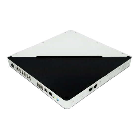
Components I/O View Refer to the diagram below to identify the components on this side of the system. Power Bottom The power switch allows powering ON and OFF the system. The hard disk LED blinks when data is being written into or read from the hard disk... - Page 9 The power LED illuminated when system been power on. HDMI 1/2/3/4/5/6 The HDMI (High Definition Multimedia Interface) (connector 6 exclusive) interface to transmitting uncompressed digital data come from E6760 (discrete graphic chip). LAN 1/ LAN2 The eight-pin RJ-45 LAN port supports a standard Ethernet cable for connection to a local network.
-
Page 10: Specification
Specification System Mainboard IB958‐58 Construction SGCC 1.0t Chassis Color Black / White Storage 2.5” 160GB SATA HDD x 1 Mounting Wall mount Power Supply 150W DC adapter Operating Temperature 0°C ~ 45°C (32°F ~ 113°F) Storage Temperature ‐20°C ~ 80°C Relative Humidity 5~90% @45°C (non‐condensing) Vibration HDD: 0.25 Grms/5~500Hz random operation Shock HDD: 15 Grms peak acceleration (11 msec duration) RoHS Available ‧ This specification is subject to change without prior notice. Mounting SI-58 to the Wall You can install SI-58 on plastic (LCD monitor), wood, drywall surface over studs, or... -
Page 11: Wall Mounting Requirements
a solid concrete or metal plane directly. Ensure the installer uses at least four M3 length 6mm screws to secure the system on wall. Six M3 length 6mm screws are recommended to secure the system on wall. Fasteners are not included with the unit, and must be supplied by the installer. The types of fasteners required are dependent on the type of wall construction. -
Page 12: Exploded View Of The Si-58 Assembly
reduces the risk that someone may accidentally walk into and damage the device. Local laws governing the safety of individuals might require this type of consideration. Exploded view of the SI-58 assembly Parts description Part NO. Description Part NO. Description Top cover Fan Bracket Heatsink-1 Front Panel... -
Page 13: Installation
Installation Installing CPU The SI-58 (IB958 board) supports rPGA988B socket for Intel® Sandy Bridge Dual Core mobile processors. The processor socket comes with a screw to secure the processor. As shown in the left picture below, loosen the screw first before inserting the processor. Place the processor into the socket by making sure the notch on the corner of the CPU corresponds with the notch on the inside of the socket. -
Page 14: Setting Jumper
(approximately 30 degrees). Note that the socket and module are both keyed, which means that the module can be installed only in one direction. To seat the memory module into the socket, apply firm and even pressure to each end of the module until you feel it slip down into the socket. With the module properly seated in the socket, rotate the module downward. -
Page 15: Jumper Locations
Jumper Locations JP1: Clear CMOS Setting Setting Function Pin 1-2 Normal Short/Closed Pin 2-3 Clear CMOS Short/Closed... - Page 16 JP2: Clear ME Setting Setting Function Pin 1-2 Normal Short/Closed Pin 2-3 Clear ME Short/Closed JP8: Flash Descriptor Security Overide (Factory use only) Flash Descriptor Security Overide Disabled Open (Default) Close Enabled Connector Locations on IB958...
- Page 17 CN1: SATA HDD Dock The SATA HDD dock combines a SATA power connector and a SATA interface connector Signal Signal Name Name V3.3 V3.3 V3.3 Reserve CN3, CN 4: Console Port (CN3 COM2, CN4 COM1) The console port is an RJ45 RS-232 serial port. Pin # Signal Name...
- Page 18 CN5: Express Card CN6, CN7, CN8, CN9, CN10, CN11: ATI E6760 HDMI Connectors Signal Name Signal Name DATA 2- DATA 2+ DATA 1+ DATA 1- DATA 0+ DATA 0- CLOCK + CLOCK - DDC CLOCK DDC DATA HOT POWER N.C. Remarks: CN6/CN7 supports HDMI.
- Page 19 CN12, CN13: Intel Chipset HDMI Connectors Signal Name Signal Name DATA 2- DATA 2+ DATA 1+ DATA 1- DATA 0+ DATA 0- CLOCK + CLOCK - DDC CLOCK DDC DATA HOT POWER N.C. Remarks: CN12/CN13 supports HDMI.
- Page 20 CN14, CN15: Gigabit LAN RJ45 Ports CN16, CN17, CN18: USB1/2/3 Ports CN19, CN20: Audio Line In and Line Out CN21: DC Power Jack (+12V only) Signal Name +12V +12V SW1: Power Button LED3: Power LED and HDD LED The green LED at the bottom is power LED. The red LED on top is the HDD LED. J1: SPI Flash Connector (factory use only) J2: LPC Connector (factory use only) J3: DDR II DIMM Socket CHA...
- Page 21 Signal Signal Name Name Ground Ground...
- Page 22 CPU_FAN: CPU Fan Power Connector Pin # Signal Name Ground +12V Rotation detection SYS_FAN: SYSTEM Fan Power Connector Pin # Signal Name Ground +12V Rotation detection AUX_FAN: SYSTEM Fan Power Connector Pin # Signal Name Ground +12V Rotation detection...
-
Page 23: Bios Setup
BIOS Setup BIOS Introduction The BIOS (Basic Input/Output System) installed in your computer system’s ROM supports Intel processors. The BIOS provides critical low-level support for a standard device such as disk drives, serial ports and parallel ports. It also password protection as well as special support for detailed fine-tuning of the chipset controlling the entire system. - Page 24 Main BIOS Setup This setup allows you to record some basic hardware configurations in your computer system and set the system clock. Aptio Setup Utility – Copright © 2010 American Megatrends, Inc. Main Advanced Chipset Boot Security Save & Exit BIOS INFORMATION System Language [English]...
- Page 25 System Time Set the Time. Use Tab to switch between Data elements. Advanced Settings This section allows you to configure and improve your system and allows you to set up some system features according to your preference. Aptio Setup Utility Advanced Main Chipset...
- Page 26 This section allows you to configure the PCI, PCI-X and PCI Express settings. Aptio Setup Utility Advanced Main Chipset Boot Security Save & Exit PCI Bus Driver Version V 2.03.00 PCI ROM Priority EFI Compatible ROM PCI Common Settings PCI Latency Timer 32 PCI Bus Clocks VGA Palette Snoop Disabled...
- Page 27 PERR# Generation Enables or Disables PCI Device to Generate PERR#. SERR# Generation Enables or Disables PCI Device to Generate SERR#. Relaxed Ordering Enables or Disables PCI Express Device Relaxed Ordering. Extended Tag If ENABLED allows Device to use 8-bit Tag field as a requester. No Snoop Enables or Disables PCI Express Device No Snoop option.
- Page 28 ACPI Settings System ACPI Parameters. Aptio Setup Utility Advanced Main Chipset Boot Security Save & Exit → ← Select Screen Enable ACPI Auto Configuration Disabled ↑↓ Select Item Enable Hibernation Enabled Enter: Select ACPI Sleep State S3 (Suspend to R…) Change Field Lock Legacy Resources Disabled...
- Page 29 Wake up event settings Enable/Disable Wake up event. Aptio Setup Utility Advanced Main Chipset Boot Security Save & Exit Wake system with Fixed Time Disabled → ← Select Screen ↑↓ Select Item Wake on Ring Disabled Enter: Select Wake on PCIE Wake Event Disabled Change Field F1: General Help...
- Page 30 CPU Configuration This section shows the CPU configuration parameters. Aptio Setup Utility Advanced Main Chipset Boot Security Save & Exit CPU Configuration Intel® Core™ i7-7210QE CPU @ 2.10GHz EMT64 Supported Max Processor Speed 2100 MHz Min Processor Speed 800 MHz Processor Speed 2100 MHz Processor Stepping...
- Page 31 Limit CPUID Maximum Disabled for Windows XP. Execute Disable Bit XD can prevent certain classes of malicious buffer overflow attacks when combined with a supporting OS (Windows Server 2003 SP1, Windows XP SP2, SuSE Linux 9.2, RedHat Enterprise 3 Update 3.) Hardware Prefetcher To turn on/off the MLC streamer prefetcher.
- Page 32 Auto Power On Schedule Advanced Main Chipset Boot Security Save & Exit [Enable Provide the Standby Power for devices. Schedule Slot 1 None [Disable] Shutdown the standby power. Schedule Slot 2 None Schedule Slot 1 Setup the hour/minute for system power on. Schedule Slot 2 Setup the hour/minute for system power on.
- Page 33 SATA Mode Determines how SATA controllers(s) operate. The options are IDE, AHCI and RAID. PCH-FW Configuration Configure Management Engine Technology Parameters. Aptio Setup Utility Advanced Main Chipset Boot Security Save & Exit Configure Management Engine Technolory Parameters. ME FW Version 7.0.4.1197 ME Firmware Mode ME Firmware Type...
- Page 34 AMT Configuration Configure Active Management Technology Parameters. Aptio Setup Utility Advanced Main Chipset Boot Security Save & Exit Intel AMT Enabled Intel AMT Setup Prompt Enabled BIOS Hotkey Pressed Disabled MEBx Selection Screen Disabled Verbose Mebx Output Enabled Hide Un-Configure ME Confirmation Disabled MeBx Debug Message Output Disabled...
- Page 35 Intel AMT Setup Prompt OEMFLag Bit 0: Enable/Disable Intel AMT Setup Prompt to wait for hot-key to enter setup. BIOS Hotkey Pressed OEMFLag Bit 1: Enable/Disable BIOS hotkey press. MeBx Selection Screen OEMFLag Bit 2: Enable/Disable MEBx selection screen. Verbose Mebx Output OEMFLag Bit 3: Enable/Disable Verbose Mebx Output.
- Page 36 Activate Remote Assistance Process Trigger CIRA boot. USB Configuration USB Configuration Parameters. Aptio Setup Utility Advanced Main Chipset Boot Security Save & Exit USB Configuration USB Devices: 2 Hubs → ← Select Screen Legacy USB Support Enabled ↑↓ Select Item XHCI Hand-off Enabled Enter: Select...
- Page 37 Device reset time-out USB mass storage device Start Unit command time-out. Device power-up delay Maximum time the device will take before it properly reports itself to the Host Controller. ‘Auto’ uses default value: for a Root port it is 100 ms, for a hub port the delay is taken from Hub Descriptor.
- Page 38 H/W Monitor Monitor hardware status. Aptio Setup Utility Advanced Main Chipset Boot Security Save & Exit PC Health Status ►Smart Fan Mode Configuration SYSTIN Temperature +46 C CPUTIN Temperature +45 C → ← Select Screen AUXTIN Temperature +47 C ↑↓ Select Item System Fan Speed 5976 RPM Enter: Select...
- Page 39 Serial Port Console Redirection Aptio Setup Utility Advanced Main Chipset Boot Security Save & Exit COM0 (Disabled) Console Redirection Port is Disabled COM4(PCI Dev0, Func0) (Disabled) Console Redirection Port is Disabled → ← Select Screen ↑↓ Select Item Serial Port for Out-of-Band Management/ Enter: Select Windows Emergency Management Services (EMS) Change Field...
- Page 40 Sandybridge PPM Configuration Aptio Setup Utility Advanced Main Chipset Boot Security Save & Exit Sandybridge PPM Configuration EIST Enabled → ← Turbo Mode Enabled Select Screen ↑↓ Select Item CPU C3 Report Enabled Enter: Select CPU C6 Report Enabled +- Change Field CPU C7 Report Enabled F1: General Help...
- Page 41 Chipset Main Advanced Boot Security Save & Exit ► System Agent (SA) Configuration ► PCH-IO Configuration System Agent (SA) Configuration Aptio Setup Utility Chipset Main Advanced Boot Security Save & Exit System Agent RC Version 1.1.0.0 VT-d Capability Supported VT-d Enabled →...
- Page 42 Intel IGFX Configuration Aptio Setup Utility Chipset Main Advanced Boot Security Save & Exit Intel IGFX Configuration IGFX VBIOS Version 2108 IGFX Frequency 650 MHz → ← Select Screen ↑↓ Select Item Primary Display Auto Enter: Select Internal Graphics Auto Change Field GTT Size F1: General Help...
- Page 43 Select DVMT5.0 Total Graphic Memory size used by the Internal Graphics Device: 128M, 256M, MAX. Gfx Low Power Mode This option is applicable for SFF only. LCD Control Aptio Setup Utility Chipset Main Advanced Boot Security Save & Exit LCD Control Primary IGFX Boot Display VBIOS Default →...
- Page 44 PCH-IO Configuration Aptio Setup Utility Chipset Main Advanced Boot Security Save & Exit Intel PCH RC Version 1.1.2.0 PCH LAN Controller Enabled Wake on Lan Disabled Azalia Auto Azalia PME Enable Disabled Azalia Internal HDMI Codec Enabled High Precision Event Timer Configuration High Precision Timer Enabled →...
- Page 45 Advanced Main Chipset Boot Security Save & Exit EHCI1 Enabled EHCI2 Enabled EHCI1 Control the USB EHCI (USB2.0) functions. One EHCI controller must always be enabled. Boot Settings This section allows you to configure the boot settings according to your preference. Aptio Setup Utility Boot Main...
- Page 46 GateA20 Active UPON REQUEST – GA20 can be disabled using BiOS services. ALWAYS – do not allow disabling GA20; this option is useful when any RT code is executed above 1MB. Option ROM Messages Set display mode for Option ROM. Options are Force BIOS and Keep Current. Interrupt 19 Capture Enable: Allows Option ROMs to trap Int 19.
- Page 47 User Password Set User Password. Save & Exit Settings Aptio Setup Utility Advanced Main Chipset Boot Security Save & Exit Save Changes and Exit Discard Changes and Exit Save Changes and Reset Discard Changes and Reset Save Options Save Changes →...
- Page 48 Reset system setup without saving any changes. Save Changes Save Changes done so far to any of the setup options. Discard Changes Discard Changes done so far to any of the setup options. Restore Defaults Restore/Load Defaults values for all the setup options. Save as User Defaults Save the changes done so far as User Defaults.
-
Page 49: Drivers Installation
Drivers Installation This section describes the installation procedures for software and drivers. The software and drivers are included with the motherboard. If you find the items missing, please contact the vendor where you made the purchase. The contents of this section include the following: IMPORTANT NOTE: After installing your Windows operating system, you must install first the Intel Chipset Software Installation Utility before proceeding with the drivers installation. - Page 50 3. When the Welcome screen to the Intel® Chipset Device Software appears, click Next to continue. 4. Click Yes to accept the software license agreement and proceed with the installation process. 5. On the Readme File Information screen, click Next to continue the installation. 6.
-
Page 51: Vga Drivers Installation
VGA Drivers Installation NOTE: Before installing the Intel(R) QM67 Chipset Family Graphics Driver, the Microsoft .NET Framework 3.5 SPI should be first installed. To install the VGA drivers, follow the steps below. 1. Insert the CD that comes with the board. Click Intel and then Intel(R) QM67/Q67 Chipset Drivers. -
Page 52: Realtek Hd Audio Driver Installation
6. On Setup Progress screen, click Next to continue. 7. Setup complete. Click Finish to restart the computer and for changes to take effect. Realtek HD Audio Driver Installation Follow the steps below to install the Realtek HD Audio Drivers. 1. Insert the CD that comes with the board. Click Intel and then Intel(R) QM67/Q67 Chipset Drivers. -
Page 53: Lan Drivers Installation
LAN Drivers Installation 1. Insert the CD that comes with the board. Click Intel and then Intel(R) QM67/Q67 Chipset Drivers. 2. Click Intel(R) PRO LAN Network Driver. 3. When the Welcome screen appears, click Next. On the next screen, click Yes to to agree with the license agreement. - Page 54 5. The wizard is ready to begin installation. Click Install to begin the installation. 6. When InstallShield Wizard is complete, click Finish.
-
Page 55: Appendix
Appendix A. I/O Port Address Map Each peripheral device in the system is assigned a set of I/O port addresses which also becomes the identity of the device. The following table lists the I/O port addresses used. Address Device Description 000h - 01Fh DMA Controller #1 020h - 03Fh...
Need help?
Do you have a question about the SI-58 Series and is the answer not in the manual?
Questions and answers