
Related Manuals for IBASE Technology ISR301


Summary of Contents for IBASE Technology ISR301
- Page 1 ISR301 Ruggedized Embedded System ® ® with NXP ARM Cortex A53 i.MX8M Quad SoC User’s Manual Document Version 1.2 (Oct. 2020)
- Page 2 No part of this publication may be reproduced, copied, stored in a retrieval system, translated into any language or transmitted in any form or by any means, electronic, mechanical, photocopying, or otherwise, without the prior written consent of IBASE Technology, Inc. (hereinafter referred to as “IBASE”).
-
Page 3: Compliance
0.1% by weight (1000 ppm) except for cadmium, limited to 0.01% by weight (100 ppm). • Lead (Pb) • Mercury (Hg) • Cadmium (Cd) • Hexavalent chromium (Cr6+) • Polybrominated biphenyls (PBB) • Polybrominated diphenyl ether (PBDE) ISR301 User’s Manual... -
Page 4: Important Safety Information
Do not try to repair, disassemble, or make modifications to the device. Doing so will void the warranty and may result in damage to the product or personal injury. CAUTION Replace only with the same or equivalent type recommended by the manufacturer. Dispose of used batteries by observing local regulations. ISR301 User’s Manual... -
Page 5: Warranty Policy
The arrangement of the peripherals • Software used (such as OS and application software) 3. If repair service is required, please download the RMA form at http://www.ibase.com.tw/english/Supports/RMAService/. Fill out the form and contact your distributor or sales representative. ISR301 User’s Manual... -
Page 6: Table Of Contents
RS232 COM Port Connector (P19) ......... 19 2.4.6 LVDS Backlight Control Connector (P18) ........ 20 2.4.7 Audio Line-In & Line-Out Connector (P9) ........ 21 2.4.8 Internal USB3.0 Connector (P7) ..........22 2.4.9 Digital I/O (GPIO) Connector (P24) ......... 23 ISR301 User’s Manual... - Page 7 4.1.1 Preparation ................35 4.1.2 Installing Toolchain ..............35 4.1.3 Building release ............... 35 For Yocto/uBuntu/Debian ................ 35 ./build-bsp-4.14.sh ................... 35 For Android ....................35 4.1.4 Installing release to board ............36 ........................37 Appendix ...................... 37 ISR301 User’s Manual...
-
Page 8: Chapter 1 General Information
Chapter 1 General Information The information provided in this chapter includes: • Features • Packing List • Specifications • Product View • Dimensions... -
Page 9: Introduction
General Information 1.1 Introduction ® ® ISR301 is an ARM -based embedded system built with NXP Cortex i.MX8M A53 processor. The device features 2D, 3D graphics and multimedia acceleration, aside from the numerous peripheral support it has that are well suited for industrial applications, including RS-232/422/485, GPIO, USB, USB OTG, LAN, HDMI interface, M.2 E2230 for wireless connectivity and a mini-... -
Page 10: Specifications
2 x RS-232 COM ports (DB9 male connector) Digital IO 8-In/Out • 1 x M.2 E-key (2230) Expansion • 1 x Mini-PCIe (interrelated with the SIM socket) Slots • 1 x SD socket (UHS-I SDR-104, 104MB/s max.) ISR301 User’s Manual... - Page 11 General Information Environment Operating -10 ~ 60 °C (32 ~ 140 °F) Temperature Relative 10 ~ 90 %, non-condensing Humidity All specifications are subject to change without prior notice. ISR301 User’s Manual...
-
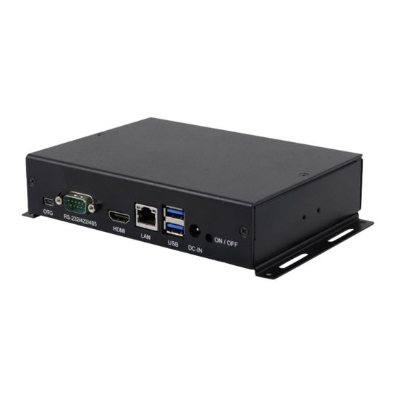
Page 12: Product View
Antenna Holes HDMI Port RS-232 COM1 & COM2 Ports GbE LAN Port GPIO Port USB 3.0 Ports Wall Mount Kit LED Indicators (from left to right: DC Jack Power, Wi-Fi status, OS status) On/Off Button SD Card Slot ISR301 User’s Manual... -
Page 13: Dimensions
General Information DIN Rail Mounting View (Optional) 1.6 Dimensions Unit: mm ISR301 User’s Manual... -
Page 14: Chapter 2 Hardware Configuration
Chapter 2 Hardware Configuration This section contains general information about: • Installations • Jumper and connectors... -
Page 15: Installations
(Insert the M.2 card in the same way as instructed above.) 2. Push the mini-PCIe card downwards as shown below, and fix the card onto the brass standoff with a screw. (Fix the M.2 card also with one screw.) ISR301 User’s Manual... -
Page 16: Wifi / Lte Antenna Installation
Wall Mounting Installation 1. Turn the device upside down. 2. Prepare at least 4 screws (M3) to Attach the wall-mount kit to the install the device on the wall. device using the supplied 4 screws. ISR301 User’s Manual... -
Page 17: Rs-232/422/485 Com Port
Hardware Configuration 2.1.4 RS-232/422/485 COM Port ➔ Assignment RS-232 RS-422 RS-485 DATA- DATA+ Ground Ground Ground ISR301 User’s Manual... -
Page 18: Com1 & Com2 Port
Hardware Configuration 2.1.5 COM1 & COM2 Port ➔ Signal Name Signal Name RXD, Receive data TXD, Transmit data Ground 2.1.6 GPIO Port ➔ Signal Name Signal Name DIO1 DIO5 DIO2 DIO6 DIO3 DIO7 DIO4 DIO8 Ground ISR301 User’s Manual... -
Page 19: Setting The Jumpers
Open When two pins of a jumper are encased in a jumper cap, this jumper is closed, i.e. turned On. When a jumper cap is removed from two jumper pins, this jumper is open, i.e. turned Off. ISR301 User’s Manual... -
Page 20: Jumper & Connector Locations On Motherboard
Hardware Configuration 2.3 Jumper & Connector Locations on Motherboard Motherboard: IBR210 ISR301 User’s Manual... -
Page 21: Jumper & Connectors Quick Reference
P1, P27 SD Card Slot HDMI Port GbE LAN Port Dual USB 3.0 Type-A Port Mini-USB OTG Port NGFF M.2 E2230 Slot Mini-PCIe Slot SIM Card Socket System ON/OFF Button Factory Use Only SW1, P25 27, 28 ISR301 User’s Manual... -
Page 22: Rtc Lithium Cell Connector (P2)
Hardware Configuration 2.4.1 RTC Lithium Cell Connector (P2) Signal Name Signal Name RTC_VCC Ground ISR301 User’s Manual... -
Page 23: Rs-232/422/485 Selection (Sw3)
Hardware Configuration 2.4.2 RS-232/422/485 Selection (SW3) Panel Type RS-422 Full Duplex RS-232 Rx/Tx (Default) RS-485 Half Duplex (TX Low-Active) RS-485 Half Duplex (TX High-Active) Function Off ISR301 User’s Manual... -
Page 24: Rs-232/422/485 Com Port (P20)
Hardware Configuration 2.4.3 RS-232/422/485 COM Port (P20) Refer to the SW3 setting for RS-232/422/485 mode selection. Assignment RS-232 RS-422 RS-485 DATA- DATA+ Ground Ground Ground ISR301 User’s Manual... -
Page 25: Lvds Display Connector (P13, P14)
Ground LCD_VDD LCD0_TX3_P LCD0_TX3_N LCD0_TX2_P LCD0_TX2_N Ground Ground LCD0_CLK_P LCD0_CLK_N BTL_PWM LCD_VDD BKLT_VCC BKLT_VCC P14: Assigment Assigment LCD1_TX0_P LCD1_TX0_N Ground Ground LCD1_TX1_P LCD1_TX1_N Ground LCD_VDD LCD1_TX3_P LCD1_TX3_N LCD1_TX2_P LCD1_TX2_N Ground Ground LCD1_CLK_P LCD1_CLK_N BTL_PWM LCD_VDD BKLT_VCC BKLT_VCC ISR301 User’s Manual... -
Page 26: Rs232 Com Port Connector (P19)
Hardware Configuration 2.4.5 RS232 COM Port Connector (P19) Assigment Assigment COM5_TXD COM3_TXD COM5_RXD COM3_RXD Ground Ground ISR301 User’s Manual... -
Page 27: Lvds Backlight Control Connector (P18)
Hardware Configuration 2.4.6 LVDS Backlight Control Connector (P18) Assigment Assigment BKLT_VCC LCD_BKLT_PWM LCD_BKLT_EN Ground ISR301 User’s Manual... -
Page 28: Audio Line-In & Line-Out Connector (P9)
Hardware Configuration 2.4.7 Audio Line-In & Line-Out Connector (P9) Pin Assigment Pin Assigment Ground LINE_IN_R Ground LINE_IN_L Ground Ground LINE_OUT_L Ground LINE_OUT_R ISR301 User’s Manual... -
Page 29: Internal Usb3.0 Connector (P7)
Hardware Configuration 2.4.8 Internal USB3.0 Connector (P7) Assigment Assigment VCC(900mA) P1_SSRX- P1_SSRX+ P1_SSTX- P1_SSTX+ P1_U2_D- P1_U2_D+ P2_U2_D+ P2_U2_D- P2_SSTX+ P2_SSTX- P2_SSRX+ P2_SSRX- VCC(900mA) ISR301 User’s Manual... -
Page 30: Digital I/O (Gpio) Connector (P24)
Hardware Configuration 2.4.9 Digital I/O (GPIO) Connector (P24) Assigment Assigment DIO5 3.3V (gpio74) DIO1 DIO6 (gpio146) (gpio75) DIO2 DIO7 (gpio147) (gpio76) DIO3 DIO8 (gpio148) (gpio77) DIO4 Ground (gpio149) ISR301 User’s Manual... -
Page 31: Mipi-Csi Connector (P10, P26)
MIPI_CSI1_CKP MIPI_CSI1_CKN MIPI_CSI1_DP0 MIPI_CSI1_DN0 MIPI_CSI1_DP1 MIPI_CSI1_DN1 MIPI_CSI1_DP2 MIPI_CSI1_DN2 MIPI_CSI1_DP3 MIPI_CSI1_DN3 CSI1_SCL CSI1_SDA CSI1_RST_B VDD_2V8 CSI1_PWEN_B VDD_1V8 CSI1_MCLK P26: Assigment Assigment MIPI_CSI2_CKP MIPI_CSI2_CKN MIPI_CSI2_DP0 MIPI_CSI2_DN0 MIPI_CSI2_DP1 MIPI_CSI2_DN1 MIPI_CSI2_DP2 MIPI_CSI2_DN2 MIPI_CSI2_DP3 MIPI_CSI2_DN3 CSI2_SCL CSI2_SDA CSI2_RST_B VDD_2V8 CSI2_PWEN_B VDD_1V8 CSI2_MCLK ISR301 User’s Manual... -
Page 32: Mipi-Dsi Connector (P12)
Hardware Configuration 2.4.11 MIPI-DSI Connector (P12) Assigment Assigment MIPI_DSI_CKP MIPI_DSI_CKN MIPI_DSI_DP0 MIPI_DSI_DN0 VCC_LCD MIPI_DSI_DP1 MIPI_DSI_DN1 MIPI_DSI_DP2 MIPI_DSI_DN2 HDMI_INT MIPI_DSI_DP3 MIPI_DSI_DN3 I2C2_SCL VCC_LCD I2C2_SDA BKLT ISR301 User’s Manual... -
Page 33: I 2 C Connector (P17)
Hardware Configuration 2.4.12 C Connector (P17) Pin Assigment Pin Assigment I2C2_SCL TP_INT_B I2C2_SDA TP_RST_B ISR301 User’s Manual... -
Page 34: Boot Mode Select (Sw1 Factory Use Only)
Hardware Configuration 2.4.13 Boot mode select (SW1 Factory use only) Panel Type USB download mode EMMC Normal Boot SD Normal Boot ISR301 User’s Manual... -
Page 35: Rs232 Debug Port (P25)
Hardware Configuration 2.4.14 RS232 Debug Port (P25) Assigment Debug_RX Deubg_TX ISR301 User’s Manual... -
Page 36: Chapter 3 Software Setup
Chapter 3 Software Setup This chapter introduces the following setup on the device: (for advanced users only) • Make a recovery SD card • Upgrade firmware through the recovery SD card... -
Page 37: Make A Recovery Sd Card
3.1 Make a Recovery SD Card Note: This is for advanced users with the IBASE standard image file only. In general, ISR301 is preloaded with O.S (Android or Yocto) into eMMC by default. Connect the HDMI cable to ISR301, and the12V-24V power directly. -
Page 38: Upgrade Firmware Through The Recovery Sd Card
Upgrade Firmware through the Recovery SD Card 1. Put the recovery files into the USB flash disk (FAT32) A) Yocto/Ubuntu: Copy all the recovery files into the PATH: /USB_flash_disk/hmsupdate/yocto/ B) Android: Copy all the recovery files into the PATH: /USB_flash_disk/hmsupdate/android/ ISR301 User Manual... - Page 39 2. Plug (Chapter 3.1.1) SD and (Chapter 3.1.2)USB flash disk into IBR210 3. Normal boot IBR210 (SW1 Pin1 OFF), start recovery eMMC automatically. 4. The update information will show on HDMI. 5. Show “Flashing successfully completed”, then power off and remove recovery SD and USB flash disk. ISR301 User Manual...
-
Page 40: Display Parameter Setting In Kernel (Feature Not Ready Yet)
1. If you have used the HDMI display, run the command below. /home/root/display_config/config_displag_mode.sh 1 2. If you use an LVDS 21.5” display, run the command below. /home/root/display_config/config_displag_mode.sh 4 Note: Script content may be changed by different LVDS models. ISR301 User Manual... -
Page 41: Chapter 4 Bsp Source Guide
Chapter 4 BSP Source Guide This chapter is dedicated for advanced software engineers only to build BSP source. The topics covered in this chapter are as follows: • Preparation • Installing Toolchain • Building release • Installing release to board... -
Page 42: Building Bsp Source
2. Decompress the IBR210 source file (e.g. ibr210-bsp.tar.bz2) into "/home/" folder. 4.1.2 Installing Toolchain Decompress Toolchain poky.tar into directory "/opt". fsl-imx-wayland-glibc-x86_64-meta-toolchain-cortexa9hf-neon-toolchain-4.14-sumo.sh 4.1.3 Building release For Yocto/uBuntu/Debian cd /home/bsp-folder ./build-bsp-4.14.sh For Android cd /home/bsp-folder source build/envsetup.sh lunch evk_8mq-userdebug make ANDROID_COMPILE_WITH_JACK=false ISR301 User’s Manual... -
Page 43: Installing Release To Board
1.copy out the following file in out/target/product/imx8mq/ 2.set board to download mode, and connect otg to usb 3. run : For 7GByte emmc uuu_imx_android_flash.bat -f imx8mq -tos -c 7 –e For 16GByte emmc uuu_imx_android_flash.bat -f imx8mq -tos –e ISR301 User’s Manual... -
Page 44: Appendix
Appendix Appendix This section provides information on the reference code. ISR301 User’s Manual... - Page 45 //open watchdog device fd = open("/dev/watchdog", O_WRONLY); //get watchdog support ioctl(fd, WDIOC_GETSUPPORT, &ident); //get watchdog status ioctl(fd, WDIOC_GETSTATUS, &status); //get watchdog timeout ioctl(fd, WDIOC_GETTIMEOUT, &timeout_val); //set watchdog timeout ioctl(fd, WDIOC_SETTIMEOUT, &timeout_val); //feed dog ioctl(fd, WDIOC_KEEPALIVE, &dummy); ISR301 User’s Manual...
- Page 46 #read data2, and compare with data1 cmp $MOUNT_POINT_STR/data2 /tmp/data1 • eMMC speed test MOUNT_POINT_STR="/var" #get emmc write speed" time dd if=/dev/urandom of=$MOUNT_POINT_STR/test bs=1024k count=10 # clean caches echo 3 > /proc/sys/vm/drop_caches #get emmc read speed" time dd if=$MOUNT_POINT_STR/test of=/dev/null bs=1024k count=10 ISR301 User’s Manual...
- Page 47 #read data2, and compare with data1 cmp $USB_DIR/data2 /var/data1 • USB speed test USB_DIR="/run/media/mmcblk1p1" # usb write speed dd if=/dev/zero of=$BASIC_DIR/$i/test bs=1M count=1000 oflag=nocache # usb read speed dd if=$BASIC_DIR/$i/test of=/dev/null bs=1M oflag=nocache ISR301 User’s Manual...
- Page 48 SD_DIR/data2 bs=1024k count=100 #read data2, and compare with data1 cmp $SD_DIR/data2 /var/data1 • SD card speed test SD_DIR="/run/media/mmcblk1" # SD write speed dd if=/dev/zero of=$SD_DIR/test bs=1M count=1000 oflag=nocache # SD read speed dd if=$SD_DIR/test of=/dev/null bs=1M oflag=nocache ISR301 User’s Manual...
- Page 49 &= ~CSIZE; options.c_lflag &= ~(ICANON | ECHO | ECHOE | ISIG); /*Input*/ options.c_oflag &= ~OPOST; /*Output*/ //options.c_cc options.c_cc[VTIME] = 150; options.c_cc[VMIN] = 0; #set parity tcsetattr(fd, TCSANOW, &options) //write ttymxc1 write(fd, write_buf, sizeof(write_buf)); //read ttymxc1 read(fd, read_buf, sizeof(read_buf))) ISR301 User’s Manual...
- Page 50 //read ttymxc1 read(fd, read_buf, sizeof(read_buf))) Audio Test // play mp3 by audio (ALC5640) gplay-1.0 /home/root/ testscript/audio/a.mp3 --audio-sink=”alsasink –device=hw:1” // record mp3 by audio (ALC5640) arecord -f cd $basepath/b.mp3 -D plughw:1,0 Note: for Android, please use apk to test. ISR301 User’s Manual...
- Page 51 -c 192.168.1.123 -i 1 -t 20 -w 32M -P 4 • Ethernet UDP test #server 192.168.1.123 run command “iperf3 -s” #communicate with server 192.168.1.123 in udp mode by iperf3 iperf3 -c $SERVER_IP -u -i 1 -b 200M ISR301 User’s Manual...
- Page 52 = (x+g_xoffset) * (g_bits_per_pixel/8) + (y+g_yoffset) * g_line_length; *(fbp + location + 0) = color_b; *(fbp + location + 1) = color_g; *(fbp + location + 2) = color_r; //close framebuffer fd close(framebuffer_fd); Note: Android is not supported. ISR301 User’s Manual...
- Page 53 *(fbp + location + 1) = color_g; *(fbp + location + 2) = color_r; //close framebuffer fd close(framebuffer_fd); • HDMI audio test #enable hdmi audio echo 0 > /sys/class/graphics/fb2/blank #play wav file by hdmi audio aplay /home/root/testscript/hdmi/1K.wav -D plughw:0,0 ISR301 User’s Manual...
- Page 54 # make sure that the simcard is inserted right, and ANT connected pppd call quectel-ppp echo "ping www.baidu.com to make sure the network ok" ping www.baidu.com Note: Due to Android includes 3G config in setting, this portion is not suit for Android version. ISR301 User’s Manual...
- Page 55 Well-Lin, 1010H MIPI-CSI Hirose Hirose P10, P26 Connector DF13E-20DP-1.25V DF13-20DS-1.25C Hirose Hirose MIPI-DSI DF13E-20DP-1.25V DF13-20DS-1.25C TechBest C Connector WT02M-30002-06132 SHR-03V-S-B Internal DC Power TechBest 2542-WS- Input 04-LF Connector types may be subject to change without prior notice. ISR301 User’s Manual...
- Page 56 //open watchdog device fd = open("/dev/watchdog", O_WRONLY); //get watchdog support ioctl(fd, WDIOC_GETSUPPORT, &ident); //get watchdog status ioctl(fd, WDIOC_GETSTATUS, &status); //get watchdog timeout ioctl(fd, WDIOC_GETTIMEOUT, &timeout_val); //set watchdog timeout ioctl(fd, WDIOC_SETTIMEOUT, &timeout_val); //feed dog ioctl(fd, WDIOC_KEEPALIVE, &dummy); ISR301 User’s Manual...
- Page 57 Appendix ISR301 User’s Manual...
Need help?
Do you have a question about the ISR301 and is the answer not in the manual?
Questions and answers