Table of Contents
Advertisement
Read this manual thoroughly and do not perform installation, operation,
maintenance, or inspection unless you fully understand all contents.
Keep this manual in a safe place where you can refer to it easily while
installing, operating, and carrying out maintenance or inspections.
This manual is for use by service personnel of our company or qualified to
perform maintenance services for this machine.
Manual No. 0153A
IWQ Series
Service Manual
First Edition
Warning
Advertisement
Table of Contents

Related Manuals for ISHIDA IWQ Series


Summary of Contents for ISHIDA IWQ Series
- Page 1 IWQ Series Service Manual First Edition Warning Read this manual thoroughly and do not perform installation, operation, maintenance, or inspection unless you fully understand all contents. Keep this manual in a safe place where you can refer to it easily while installing, operating, and carrying out maintenance or inspections.
- Page 2 This manual is edited for servicing personnel. Use by other personnel is not permitted. • This manual may be revised in accordance with modification when made in the machine. • All rights are reserved. Copying any part of this manual is prohibited without our permission. IWQ Series Service Manual 1/54...
-
Page 3: Table Of Contents
3.3.10 C9 Mode A/D flickering check, I/F inspection mode ............30 3.4 Country No. List .......................31 3.5 Scale No. List ........................32 3.6 EEPROM Map........................33 EEPROM (0 ∼ 127) data format..................33 3.6.1 3.6.2 Measurement conditions setup table .................35 IWQ Series Service Manual 2/54... - Page 4 5.1 Periodical Replacement Parts..................48 5.2 Replacing and Adjusting Load Cell ..................48 5.3 Troubleshooting .......................51 Chapter 6 Others (Appendix) ..................54 6.1 RS-232C Connecting Cables (Optional) ................54 6.1.1 RS232C cable DSUB9Pin ....................54 6.1.2 RS232C cable DSUB25 Pin ....................54 IWQ Series Service Manual 3/54...
-
Page 5: Chapter 1. Product Overview
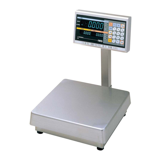
Chapter 1. Product Overview 1.1 Product Overview • The IWQ Series is waterproof type electronic scale (waterproof conforming to the class IP-65). • Both IWQ-150 and IWQ-30 are equipped with checking and counting functions for the upper and lower limits of weight. -
Page 6: Appearance
1.3 Appearance IWQ-150 Rear of display Display fastening Display knob Display pole Weighing platter Display Level pole indicator Bracket base Level adjusting Bracket foot 1.4 Appearance of Operation Panel Common to IWQ-150 and IWQ-30 European specification IWQ Series Service Manual 5/54... - Page 7 Asian specification Chinese specification 重量 IWQ Series Service Manual 6/54...
-
Page 8: Chapter 2. Installation, Placement And Setup
Chapter 2. Installation, Placement and Setup 2.1 Outer Dimensions IWQ-150 Unit: mm IWQ-30 Unit: mm IWQ Series Service Manual 7/54... -
Page 9: Procedures Of Installation And Placement
4 points. The bracket is asymmetric about the mid-horizontal line. The figure in the right shows the direction Rounded corner of the bracket when it is fastened. with greater Fit position radius is on top. Bracket IWQ Series Service Manual 8/54... - Page 10 6. (1) Push the ON/OFF key on the operation panel for display. (2) Initialize the Test Mode to ensure that weighing capacity and span (weight) meet. (3) Base operation-related training for users on the User’s Manual. IWQ Series Service Manual 9/54...
-
Page 11: Chapter 3. Each Setting Mode
The start-up procedure for registration, setup and test mode requires pressing the Caution ON/OFF key while the scale is OFF (immediately while the buzzer is sound-ing), then pressing the CALL , CLR and 1 keys for a while. IWQ Series Service Manual 10/54... -
Page 12: Setup Mode
5: 38400bps 0: Specifically designed Selecting serial for printer. output format Refer to Item 4 Reference 1: DAP-01 format Output format. Reference 2: IWQ1 format (DAP-01 expanded) 3: MZ-7000 format 4: IWQ2 format (MZ-7000 expanded) IWQ Series Service Manual 11/54... - Page 13 Under & Stable Accept display Over Stable Under Accept Over Tare Under Accept Over deduction Selecting 0: “ON/OFF” key relay input 1: “TARE” key 2: “ZERO” key 3: Scale data output (same response as O8 command) IWQ Series Service Manual 12/54...
- Page 14 4: Only during key input or when stable; 5: Only during key input 6: Upper/lower limits verification function; (regardless of being stable/unstable) UNDER: Successive “Blips” with an interval ACCEPT : Long continuous “Beeps” OVER : Successive “Blips” IWQ Series Service Manual 13/54...
-
Page 15: Start-Up Of Setup Mode, Setup, And End Of Setup
(3) Input item number and call up. then press CALL . Input item number(s) 3. Setting data Input data and set using the PCS key. Normal display 4. End of setup Press the ZERO key. IWQ Series Service Manual 14/54... -
Page 16: Input Command Format
For an insufficient text receipt, the receipt buffer will be reset if LF (OAH) is received. • Input command text (0DH) (0AH) Command Terminator • Response command text Affirmative response (06H) Negative response (15H) IWQ Series Service Manual 15/54... - Page 17 Not executed within 1 second. Character Having received an invalid text. Code (15H) Having received an invalid command. Timing: Upon receiving an invalid text/command. Upon verifying outside execution range. 1 second elapsed after receiving a command. IWQ Series Service Manual 16/54...
- Page 18 No output within 1 second (for O8 command). Command Having received an invalid text. Character Having received an invalid command Code (15H) Timing: Upon receiving an invalid text/command. Upon verifying outside scale operation range. 1 second elapsed after receiving a command. IWQ Series Service Manual 17/54...
-
Page 19: Output Format
<Output when weight conditions meet, even the quantity number is zero> <個数が0の場合でも、重量条件一致で出力する> ∗ With Japanese specifications (country code 10), does not print “PT” (prints “T” instead), or “N”. ※ 国内仕様(国コード10)では、'PT'の印字なし(代わりに'T'印字) ∗ The sub-total is printed automatically when weight / unit is changes. ※ 単重変更時、自動的に小計印字を行う IWQ Series Service Manual 18/54... - Page 20 5) Necessary/not necessary toggling for Serial No. print is changeable. 5)シリアルNo.印字あり/なしの切替可能 (when print is not necessary, the sub-total is not printed.) 6) Selting for single chit print is possible (6 line feeding) after printing. (印字なし設定の場合、小計印字機能なし) 6)単票印字(印字後6行改行)仕様に設定可能 IWQ Series Service Manual 19/54...
- Page 21 E (45H): Weight value is over the scale or error. - (2DH): Weight negative kg (6BH, 67H): kg g (20H, 67H): g lb (6CH, 62H): oz oz (6FH, 7AH): oz CR = 0DH ps (70H, 73H): pcs LF = 0AH IWQ Series Service Manual 20/54...
- Page 22 30H: Weight value is stable. For example, weight value 12345 is to 31H: Weight value is unstable. read; 32H: Weight value is over the scale or 01:12345.6 error. 02:1234.56 05:1.23456 STX = 02H ETX = 03H IWQ Series Service Manual 21/54...
-
Page 23: Test Mode
Test item number displayed 2. Return to the Test Mode initial display Same as above. Press UNDER Limit key. (Not available during key check in the C2 mode) 3. End Display turns OFF. Press ON/OFF key IWQ Series Service Manual 22/54... -
Page 24: C1 Mode ⋅⋅ Country No. Scale No. And Span Adjustment
5. Zero adjustment Press the ZERO key. Set the A/D converter count value to 20000 for the zero point adjustment. ∗ Press PCS key to switch between lb/kg specifications. A/D converter count value (For USA only) IWQ Series Service Manual 23/54... - Page 25 True A/D converter data 9. Data memory Inpulting into EEPROM is necessary when changes are made to Country No., Scable No., or Span adjustment. • Press MEMORY on the main board. While A/D converter data is displayed; IWQ Series Service Manual 24/54...
- Page 26 ♦ Memory switch Remove 10 screws fastening the display case, the seal on the back of the case, and the seal screws. The memory switch is located on the main board P-932-2 as illustrated. IWQ Series Service Manual 25/54...
-
Page 27: C2 Mode ⋅⋅⋅⋅ Key Check
(Example: Press the CALL key.) Key data Keys and key data Key data Key data Key data ZERO OVER TARE TARE SET UNDER CALL 3. How to end key check In the OFF state. Press the ON/OFF key. IWQ Series Service Manual 26/54... -
Page 28: C3 Mode ⋅⋅⋅⋅ Display Check (1)
Press the ten-key 4 and confirm it by pressing the TARE key. Set data Input data Check digits successively from segments a to g. (The illustration is omitted) 2. Ending display check (2) Press the UNDER key. IWQ Series Service Manual 27/54... -
Page 29: C5 Mode ⋅⋅⋅⋅ Program No. Display
4. Ending initialization Press the UNDER key. The program starts at Test Mode when the initialization flag is set. The flag is reset when span adjustment is performed, and the normal mode then becomes available. IWQ Series Service Manual 28/54... -
Page 30: C7 Mode ⋅⋅⋅⋅ Individual Setup Of Country Specifications And Weighing Conditions
The address ranges from 0 to 127. TARE key: address going forward. ZERO key: address going backward. Note Address Data This data can not be changed nor looked into for maintenance service. 3. Ending C8 Mode Press the UNDER key. IWQ Series Service Manual 29/54... -
Page 31: C9 Mode A/D Flickering Check, I/F Inspection Mode
When stable When unstable. 3. I/F check (for factory inspection) ∗ Requires an inspection tool connector. Press the CLR key to return to C9 Mode. Press the TARE key. Error if not using the tool. IWQ Series Service Manual 30/54... -
Page 32: Country No. List
When this switching function is used, difference not exceeding 0.2 in scale (0.2 e) may occur in the measurement immediately after switching. However, the difference will be compensated by zero point adjustment (or zero tracking) and correct measurement is guaranteed. When using only lb or kg specifications, North America 1 should be used. IWQ Series Service Manual 31/54... -
Page 33: Scale No. List
60lb/ 30kg (1/3000) Multi-interval 30lb/ 15kg (1/3000) Multi-interval 15lb/ 6kg (1/3000) Individual weighing capacity setup ∗ Individual weighing capacity “99” can not be set. It is displayed only when setup is changed in C7 mode. IWQ Series Service Manual 32/54... -
Page 34: Eeprom Map
105A Contact input signal setup (bit4∼7) 0∼16 (F14) 105B Loud buzzer output setup (bit0∼3) 0∼16 (F15) 106A Internal buzzer selection function (bit4∼7) 0∼16 (F16) 106B 107A Reserve 107B Reserve 102 ∼ 109 checksum 108∼109 ― IWQ Series Service Manual 33/54... - Page 35 0 ∼ 15 1 ∼ 16 areas 125A Area code (refer to area code table) 125B Span adjusted flag 5H or others 5H = OK others = Error No. 100 ∼ 113 checksum ― 126,127 IWQ Series Service Manual 34/54...
-
Page 36: Measurement Conditions Setup Table
6: 1.31 Hz 5.00 Hz 200 ms 8: 1.68 Hz 6.40 Hz 156 ms A: 2.10 Hz 8.00 Hz 125 ms C: 2.62 Hz 10.00 Hz 100 ms E: 3.35 Hz 12.80 Hz 78 ms IWQ Series Service Manual 35/54... - Page 37 <Printer output form> <with ’PT’,’N’ prints> <without ‘PT’,’N’ prints> Counting function 0: Available 2: Not available Weight unit cursor 0: Normally lighting 4: Lighting shutoff for non indication (at normal switching switching lb-kg) (Not available) (Available) Reserve IWQ Series Service Manual 36/54...
-
Page 38: Chapter 4. Hardware Configuration
Chapter 4. Hardware Configuration 4.1 Mechanisms 4.1.1 Display section (IWQ-30/150 common) IWQ Series Service Manual 37/54... -
Page 39: Scale Section
4.1.2 Scale section IWQ-30 IWQ Series Service Manual 38/54... - Page 40 IWQ-150 IWQ Series Service Manual 39/54...
- Page 41 ♦Load Cell AT-50 (IWQ-30) Strain gage Butyl rubber Silicon coat Aluminum frame Water-proof lock Bushing Load cell cable 3m ♦Load cell AT-200 (IWQ-150) Strain gage Butyl rubber Silicon coat Water-proof lock Bushing Load cell cable 3m Aluminum frame IWQ Series Service Manual 40/54...
-
Page 42: Display Pole Section
4.1.3 Display pole section Display angle adjusting knob Display pole Bracket Cell cable (cell cord) Parts in the same package IWQ Series Service Manual 41/54... -
Page 43: Electric Concerns
4.2 Electric Concerns 4.2.1 Block diagram IWQ Series Service Manual 42/54... -
Page 44: Main Board P-932
PIN No. to P-933 PIN No. to P-933 Signal code Signal code ASWF2 ASWR2 ASWF1 DRDY ASWR1 SCLK AIN+ STANBY AIN- (4) Connector XJ3 • +5VDC input PIN No. Signal code Wire color to power supply IWQ Series Service Manual 43/54... -
Page 45: A/D Board P-933
• Load cell-connecting terminal with screws • Tools: 2.5 mm Phillips screwdriver, or [Soldering side] flatblade screwdriver for adjustment. Terminal No. Signal code Wire color Contents Cell supply +5V White Input + Green Input − Blue IWQ Series Service Manual 44/54... -
Page 46: I/F Board P-934-1 (Option)
“relay input Orange select” in Setup IN1 (C) Input Mode F14. cathode Empty Refer to “relay output setup” in “Setup Mode F13” and “relay input Reference select” in “Setup Mode F14”, for input/output contents. Reference IWQ Series Service Manual 45/54... - Page 47 Circuit diagram I/F board P-934 IWQ Series Service Manual 46/54...
-
Page 48: Sw Power Supply
SW power supply Fastener ∗Outer shape of power plug varies according to country. (2) Connector CN2 A PIN No. Signal code Wire color B, to main board XJ3 Fastener PH Connector 4P (JST) XH Connector 4P (JST) IWQ Series Service Manual 47/54... -
Page 49: Chapter 5. Maintenance
Seal Sealing screw Front case 5.2 Replacing and Adjusting Load Cell Specifications Input Output Insulation Type Model code Rated output resistance resistance resistance 2.3mV/V±15% 2000∼2600Ω 2000∼2600Ω 10GΩ IWQ-150 LC'AT-200' 2.3mV/V±15% 2000∼2600Ω 2000∼2600Ω 10GΩ IWQ-30 LC'AT-50' IWQ Series Service Manual 48/54... - Page 50 The cell cable may rupture when forcefully pulled. Surface flaws may invite water Caution intrusion and inner corrosion, resulting in fluctuated measurement and/or other malfunctioning. (8) Confirming the lower limit IWQ Series Service Manual 49/54...
- Page 51 Spacer (10) Confirming and adjusting the four-corner limit gaps Refer to Item 2. C1 Mode, Section 3. Test Mode in Chapter 3. Setup Mode, in Reference this manual for zero point and span adjustment. Reference IWQ Series Service Manual 50/54...
-
Page 52: Troubleshooting
1.Influence of wind or • If the scale is exposed to wind, fluctuated. vibrations at the set move the scale to an other location. place, etc. • If influenced by vibrations from floor or platform, move the scale. IWQ Series Service Manual 51/54... - Page 53 • Check that there is connection via the main board XJ4 connector. • Replace the main board. 1.Mis-matching transmission • Confirm that the scale side and 2. Mis-printing (garbled) specifications the printer side match. • Replace the main board. IWQ Series Service Manual 52/54...
- Page 54 • Check the XJ4 connector and 2. Insufficient conductivity at contact. harness C2 RS232C for contact or disconnection. • Check for contacts or disconnection of the cable coming from the loud buzzer. • Replace the main board. 3. Board-related defect. IWQ Series Service Manual 53/54...
-
Page 55: Chapter 6 Others
A PH connector PIN No. Signal code Wire color B D-SUB 25 PIN No. White Green Black RTS/CTS Orange 4 (4/5 jumper wire) RTS/CTS Orange 5 (4/5 jumper wire) Terminal C Shield wire Shield wire Connected at the shell IWQ Series Service Manual 54/54...
Need help?
Do you have a question about the IWQ Series and is the answer not in the manual?
Questions and answers