
Subscribe to Our Youtube Channel
Related Manuals for MAHA ZS SQUARE II 3.5


Summary of Contents for MAHA ZS SQUARE II 3.5
- Page 1 ZS SQUARE II Two Post Lifts with Flat Head or Swing Arm Supports Original Operating Instructions BA322301-en ZS SQUARE II 3.5 ZS SQUARE II 4.5 ZS SQUARE II 5.5 ZS SQUARE II 6.5...
- Page 2 MAHA's claim is to also be a leader in the areas of reliability, safety and sustainability – this can be seen in many details that have been developed with these aspects in mind.
-
Page 3: Table Of Contents
Contents General Safety Instructions ..........................5 Introduction ..............................5 Symbols and Signal Words ......................... 5 1.2.1 Personal Injury ............................5 1.2.2 Property Damage ..........................5 What to Do in the Event of Defects or Malfunctions ................. 6 What to Do in the Event of an Accident ...................... 6 Requirements for the Operating Personnel .................... - Page 4 4.6.3 Wheel Engaging Support........................33 4.6.4 Ceiling Light Barrier ..........................34 4.6.5 Cable Remote Control ......................... 35 Troubleshooting ............................35 Troubleshooting ............................. 35 Safety Information ............................. 35 LED Signal Codes ............................37 Error Table ..............................39 Inspection ............................... 40 Safety Information ............................. 40 Daily Inspection before Starting Work ......................
-
Page 5: General Safety Instructions
General Safety Instructions Introduction • These operating instructions must be read carefully and understood before work commences. • Please observe the specific safety information provided for the respective sections of the operating instructions. • Adhering to the procedures, sequences and corresponding safety instruc- tions is essential. -
Page 6: What To Do In The Event Of Defects Or Malfunctions
What to Do in the Event of Defects or Malfunctions • If any irregularities occur, immediately lower or support the lift to the basic position. • Turn off the main switch and secure against unauthorised use. • Contact service team. What to Do in the Event of an Accident •... -
Page 7: Intended Use
have under operational conditions in the sequence and how wear, aging and the like will affect the safety of the lift. Intended Use • The lift is intended exclusively for the safe lifting and lowering of passenger cars and commercial vehicles up to the total weight according to the type plate within the scope of service and repair work. -
Page 8: Description
Description Applicable Standards and Directives The lift has been designed in accordance with the applicable standards and regulations. The most important of these are: • 2006/42/EC Machinery Directive • 2014/30/EU Electromagnetic Compatibility Directive • 2014/35/EU Low Voltage Directive • DIN EN 1493:2011 Vehicle Lifts •... -
Page 9: Control Description
to the foundation. The piston rod is guided in the cylinder head. An anti-rotation device mounted in the piston rod and tank tube prevents the piston rod from rotating. A mechanical end stop limits the maximum stroke of the lift. The cylinder head also guides the toothed rack. -
Page 10: Safety Devices
lift is equipped with additional options, it is equipped with the large control element. 2.3.3 Safety Devices • Synchronisation connection The lifting units are connected to a synchronous shaft via the toothed racks. This limits the height offset between the two piston rods to a maximum of 50 mm. -
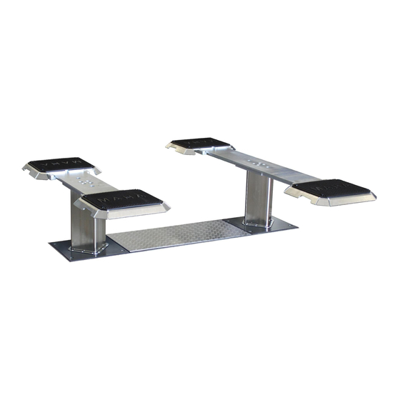
Page 11: Overall View With Components
2.3.4 Overall View with Components Lifting unit Lifting unit left Switch rod Lifting unit right Lifting column Clamping element Synchronisation connection Cover Hydraulic cylinder Hydraulic power unit Installation box (incomplete illustration) BA322301-en... - Page 12 Flat head support Illustration without rubber pad Flat head Rubber pad Pull-out Grooved pin BA322301-en...
- Page 13 Swing arm support Swing arm carrier Support plate Support arm, telescopic Lock BA322301-en...
-
Page 14: Technical Data
Technical Data 2.4.1 Danger Zone 1000 mm 1000 mm 1000 mm 1000 mm 1000 mm 1000 mm 1000 mm BA322301-en... -
Page 15: Technical Data
2.4.2 Technical Data ZS SQUARE II model Rated load capacity [kg] 3500 4500 5500 6500 Stroke height [mm]* 1900 1890 Installation depth incl. installation 2395 2395 box T [mm]* 2690 Post spacing SA [mm]* 1350 2300 2500 2700 Clear width between lifting units SA - 400 LW [mm]* Overall width head plate-... -
Page 16: Set-Up Diagrams
2.4.3 Set-up Diagrams BA322301-en... - Page 17 ZS SQUARE II model 3.5 FT Pull-out Standard Long Wide a max* [mm] BG max* [mm] SA + 530 SA + 530 SA + 810 LG* [mm] 2086 2286 2086 BA322301-en...
- Page 18 ZS SQUARE II model F [mm] SA + SA + SA + SA + SA + SA + SA + SA + BG* [mm] 1360 2030 2030 DP* [mm] SA + 2 x F SA + SA + SA + SA + SA + SA +...
-
Page 19: Transport, Handling And Storage
Transport, Handling and Storage Safety Information WARNUNG • Wear personal protective equipment. • Standing under a suspended load is prohibited. • Transport and storage of packages is allowed only in original packaging • Before removing the packaging straps, secure the packages against falling and maintain a safe distance. -
Page 20: Operation
Operation Safety Information WARNUNG • Comply with legal accident prevention regulations. • Wear personal protective equipment. • Carry out visual and operational checks daily before the commencement of work (see also section “Inspection and maintenance schedule”). • Defects must be corrected immediately in a competent manner. •... - Page 21 load during the lifting and lowering process. • Monitor the load and the lift during lifting and lowering. In the event of ir- regularities, one of the emergency stop switches must be actuated immedi- ately (main switch on the control box or emergency stop button on the ca- ble remote control).
-
Page 22: Preparations
Preparations 4.2.1 Initial Position/Ready for Operation • The main switch must be at position 0. • The lift must be lowered all the way down. Preparing the support: Flat head support • The pull-outs must rest fully on the flat head support. •... -
Page 23: Positioning Of The Supports
4.2.3 Positioning of the Supports Flat head supports Lift the pull-outs at the front and move them so that the pull-outs are positioned as accurately as possible under the pick-up points. The notched pin must engage in one of the holes in the pull-out. CAUTION •... - Page 24 Swing arm supports By swiveling and pulling out the support arms, bring the support discs under the support points specified by the vehicle manufacturer. Rotate the support discs so that all four support points are reached evenly. Use support disc raisers as required. WARNING The support disc raisers with a length of 300 mm are only available for a load of 4500 kg and higher.
-
Page 25: Raising And Lowering Cycles
Raising and Lowering Cycles WARNING When installing or removing heavy vehicle components, ensure that the centre of gravity does not shift to a dangerous extent! The vehicle may tip off the lift. The vehicle must be secured against tipping by suitable means. 4.3.1 Control Elements The buttons of the control elements are assigned with the following functions:... - Page 26 Large control element Function Short form Comments Raise the lift LIFT UP Lower the lift LIFT DOWN Lift wheel-free jack WFJ UP Lower wheel-free jack WFJ DOWN without function, only Multifunction key 1 for service personnel without function, only Multifunction key 2 for service personnel LED light, red: see section “LED Signal...
-
Page 27: Checking The Support And The Lifting Process
Function Short form Comments Lighting – switches on above the pinch protection, off below = LED on – is always off = LED off 4.3.2 Checking the Support and the Lifting Process Set the main switch to position I and wait until the control unit is ready for operation. -
Page 28: Driving Off The Lift And Changeover
Driving off the Lift and Changeover • Lifts with swing arm supports: After the lift has been lowered completely, turn the support arms out to the side and bring them back into home posi- tion. • All supports: Then drive the vehicle off the lift. WARNING Contact of the support arms with the wheels or other vehicle parts during drive- off can cause damage to the support arm lock. -
Page 29: Emergency Lowering
Emergency Lowering WARNING In the event of an emergency lowering, the safety devices of the lift are completely or partially overridden. Emergency lowering may only be performed by trained personnel. The lift must not be put back into operation until the fault has been rectified. In the event of an electrical or mechanical malfunction, two emergency lowering options are available for the lift. -
Page 30: Mechanical Emergency Lowering
4.5.2 Mechanical Emergency Lowering The mechanical emergency lowering takes place via the bleeding blocks of the lifting units. +C-M2.B +C-M2.A Remove the centre cover and store it outside the danger zone (see section “Danger zone”. WARNING The lift can/will lower on one side when the respective lowering valves are opened (tilt on one side approx. -
Page 31: Optional Equipment
Optional Equipment 4.6.1 Hinged Cover Frame To lower lifts with swing arm supports to floor level, they can be supplied with a hinged cover frame. NOTICE The hinged cover frame must be set in concrete with the installation box. A subsequent installation is no longer possible. - Page 32 BA322301-en...
-
Page 33: Installation Frame For Flat Head Lifts
4.6.2 Installation Frame for Flat Head Lifts CAUTION In this installation situation, there is no floor compensation; when raised, this results in additional tripping hazards. This must be observed when working on the vehicle. 4.6.3 Wheel Engaging Support Lifts with a nominal load capacity of 4500 kg and above can be equipped with wheel engaging supports as an alternative to the disc supports. -
Page 34: Ceiling Light Barrier
NOTICE Lightly grease the sliding surfaces before mounting the wheel engaging supports. Screw the support disc all the way down (protruding at the bottom) and remove it. Position the guide plate (A) and insert the support pin (B). Screw in fastening screws (C) and tighten them hand-tight. Make sure that there is no tension between support pin and guide plate. -
Page 35: Cable Remote Control
4.6.5 Cable Remote Control WARNING Connection only permitted by qualified electrician. The operator is responsible for ensuring that nobody is within the danger area. A cable remote control is optionally available for the lift. With this it is possible to operate the lift away from the control box. This gives the operator the opportunity to gain improved visibility into the hazardous area. - Page 36 after the system has been switched off! • Maintenance and repair work should only be carried out when the lift is load-free. • Only use original replacement parts. • Substances that are hazardous to the environment must be disposed of appropriately.
-
Page 37: Led Signal Codes
In case of recurrence, contact MSC. Replace roller feeler. Switch monitoring „CE Lights Flashes 8x In case of recurrence, stop“ contact MSC. *MSC = MAHA Service Center Large control element LED code Status/ Note / Error Remedy YELLOW GREEN Equipment ready for Lights... - Page 38 Switch monitoring “Lift up” In case of recurrence, contact MSC. Replace “Lift up” sensor. Switch monitoring Lights Flashes 10x --- In case of recurrence, “CE stop” contact MSC. Lights Service interval expired Contact MSC. *MSC = MAHA Service Center BA322301-en...
-
Page 39: Error Table
Axle lift is not in defined end Push axle lift into defined position end position Lift with pneumatic lifting floor and axle lift cannot be Position switch for defined lowered completely end position of axle lift de- Notify MSC fective/misadjusted *MSC = MAHA Service Center BA322301-en... -
Page 40: Inspection
Inspection Depending on the conditions of use, the lift must be inspected at intervals of no more than 12 months. In particular, safety devices, fastenings and load-bearing components must be inspected. This inspection must be carried out by a competent person to ensure safe operation also until the next inspection. The inspection and its findings shall be documented. -
Page 41: Daily Inspection Before Starting Work
Daily Inspection before Starting Work All checks must be carried out with the system in an unloaded condition! 6.2.1 Cables and Actuators Cables must not show any visible damage. Cables with visible pinch points, damaged sheathing, kinks or clanks must be replaced immediately with new ones. -
Page 42: Load Supports
6.2.5 Load Supports A = Rubber pad B = Support plate with thread Support plates take over the load and hold it in position. The rubber pad yields selectively under load. This protects the vehicle's lifting point and prevents the vehicle from slipping. -
Page 43: Six-Monthly Inspection
Six-Monthly Inspection 6.3.1 Oil Level and Hydraulic Oil Trouble-free operation of the lift is only possible with functioning hydraulic oil. The hydraulic oil may be non-functional if it has the following characteristics and should then be replaced immediately: • Turbidity •... -
Page 44: Tightness Of The Hydraulic System
All accessible weld seams shall be visually inspected for irregularities, such as cracks or corrosion. In the event of such an irregularity, do not continue to operate the lift under any circumstances. The MAHA Service Center must be contacted immediately. - Page 45 • Damage to the outer layer (e.g. scuff marks, cuts, cracks) • Embrittlement of the outer layer • Deformations that do not correspond to the natural shape of the hose or hose assembly (both in depressurised and pressurised condition) • Storage and or use period of the hose BA322301-en...
-
Page 46: Maintenance
Maintenance In order to ensure the safe operation and function of the lift, maintenance must be carried out at the latest after the intervals of the maintenance plan to the extent described. Maintenance work may only be carried out by specially trained and authorised personnel. -
Page 47: Lubrication
Lubrication NOTICE Only the following lubricants are permitted for maintenance of the lift! Lubrication point Lubricant – Piston rod Hydraulic oil HLP-D 22 (HLP-D 22 Synth) – Support arm pull-outs – Threads of support plates Multipurpose grease – Support arm lock –... -
Page 48: Hydraulic Hose Lines
Hydraulic Hose Lines NOTICE Hydraulic hose lines that have already been used must not be used to repair damaged hydraulic hose lines. In the event of damage of any kind, hydraulic hose lines must be replaced with new ones. In addition, hydraulic hose lines must be replaced after six years at the latest due to aging processes. - Page 49 Check the oil level in the hydraulic unit and top up with hydraulic oil if necessary. Venting with mounted support structure The lift is in a completely retracted state. Extend the lift about halfway. Remove the middle sealing plug (C) of the respective holder. Further steps analogous to section “Bleeding via the lifting unit”.
-
Page 50: Care Instructions
Care Instructions NOTE • Any damage to the paintwork should be repaired immediately to prevent corrosion. • To prevent damage, cleaning work must not be carried out with harsh clea- ners or with high and steam pressure equipment. Repairs NOTICE See repair instructions in the lift's technical handbook. - Page 51 MAHA Maschinenbau Haldenwang GmbH & Co. KG, Hoyen 20, 87490 Haldenwang, Germany Haldenwang, 2022-08-08 Andreas Maier CE-Bevollmächtigter | Authorised CE Representative MAHA Maschinenbau Haldenwang GmbH & Co. KG ꞏ Hoyen 20 ꞏ 87490 Haldenwang ꞏ Germany ☎ +49 8374 585-0 | maha@maha.de | www.maha.de...
- Page 52 PL670000_002-de...
Need help?
Do you have a question about the ZS SQUARE II 3.5 and is the answer not in the manual?
Questions and answers