Table of Contents
Advertisement
Quick Links
Advertisement
Table of Contents
Troubleshooting

Related Manuals for HANGCHA CDD12-AC1


Summary of Contents for HANGCHA CDD12-AC1
- Page 1 Hi Range CDD12/14/16/20-AC1 ELECTRIC STACKER CDD12/14/16/20-AZ3 CTD12/14/16/20-AC1 CTD12/14/16/20-AZ3 CDD12/14/16/20-AC1S CDD12/14/16/20-AZ3S CTD12/14/16/20-AC1S CTD12/14/16/20-AZ3S OPERATION AND MAINTENANCE MANUAL Original Instruction HANGCHA GROUP CO., LTD. 11/2018...
- Page 2 FOREWORD Thank you very much for purchasing the A series hi range electric stacker of Hangcha Group . A series hi range electric stacker is a newly developed product for warehouse logistic, it owns characteristics as advanced performance, comfort operation, safety and security, low maintenance cost, and is an ideal tool for handling goods in warehouse, supermarket and workshop.
-
Page 3: Table Of Contents
Content Part Ⅰ: Operation and maintenance ................... 1 Truck Introduction ........................1 1.1 General ............................ 1 1.2 Use occasion and condition ..................... 3 1.3 Main part name ........................4 1.4 Display and control ........................7 1.4.1 Display ............................. 8 1.4.2 Control ........................... 10 1.4.3 Others ............................ - Page 4 1.3.3 Brake air gap adjustment ...................... 86 1.3.4 Maintenance .......................... 87 1.3.5 Common fault and troubleshooting ..................88 Hydraulic system ........................89 2.1 Hydraulic system working principle ..................90 2.2 Hydraulic unit ......................... 91 2.3 Hydraulic unit dismantle......................95 2.4 Hydraulic system fault diagnosis and correction ..............96 Electric system ........................
-
Page 5: Part Ⅰ: Operation And Maintenance
Part Ⅰ: Operation and maintenance Truck Introduction 1.1 General This manual introduces A series hi range electric stacker. According to different operation way, it has two types as pedestrian-type and Stand-on type. Users can get relevant information as rated load from the product model. Model CDD20-AC1S as an example: CDD20-AC1S Mode... - Page 6 Truck body system – Beautiful and compact outline, concise and fluent line. – Chassis welded by high-performance steel plate guarantees enough load capacity. – Chassis adopts 4-wheel structure, including one drive wheel, one auxiliary wheel as stabilizing and two load wheels, thus guarantee the good stability and safe travelling. –...
-
Page 7: Use Occasion And Condition
1.2 Use occasion and condition Truck in this manual is only for lifting and transporting loads. It must be used, operated and maintained according to the information in this manual. Any other uses are outside the design envelope and can lead to injury to persons or damage to equipment or property. -
Page 8: Main Part Name
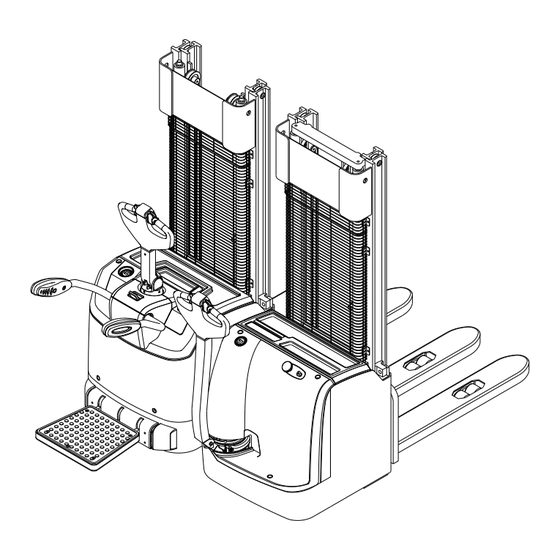
1.3 Main part name Pedestrian-type: CDD12/14/16/20-AC1, CDD12/14/16/20-AZ3... - Page 9 Stand-on type: CDD12/14/16/20-AC1S, CDD12/14/16/20-AZ3S...
- Page 10 Item Description Item Description Control handle Frame Instrument Load wheel Arm guard lock switch Fork Key switch Arm guard Emergency stop switch Rear hood assy Driving wheel Battery cover Mast Pedal Auxiliary wheel...
-
Page 11: Display And Control
1.4 Display and control... -
Page 12: Display
recharged. 1.4.1 Display Hourmeter indicator(green LED) Curtis 840 Instrument [2] Said when the green LED light is normally on the timer is timing, the smallest unit of time for 0.1 hours. Every time when starting the vehicle LCD screen will display the vehicle's total run time, this time is for regular maintenance on the basis of the vehicle. - Page 13 appears. The string shown on the display is XXAYY, where XX and AYY represent respectively the alarmed node and the alarm It is normally off; when it appears (fixed) it code. The alarm code meaning must be shows request programmed present in the controller user manual.
-
Page 14: Control
1.4.2 Control Control handle Key switch [12] Control truck steering and braking. When turn the control handle right and left, it can realize the truck right and left turn. The max turning angle of this handle is about 175°. Turn on the key switch, and the power is on. Turn When press the handle to horizontal position off the switch, and the power is off. - Page 15 Press this button and indicator light[19] is on, it means the truck changes to low speed travel mode. When in low speed mode, the truck will travel in low speed, 40% of max. travelling speed. – Press this control handle downwards. Press this button and indicator light[19] is off, it Turn this button towards the side of body means the truck changes to normal travelling...
-
Page 16: Others
1.4.3 Others Rear hood assembly [5] When check battery, take out the plug, charge or replace the battery, you can easily open the battery cover. There install main parts as hydraulic unit, main drive unit and electric system etc. under the CAUTION hood. -
Page 17: Standard Technical Data
1.5 Standard technical data The following technical data are all standard data. Our company reserves the right of alteration and extension. Model CDD12-AC1 CDD14-AC1 CDD16-AC1 CDD20-AC1 Operator type Pedestrian Pedestrian Pedestrian Pedestrian Load capacity Q (kg) 1200 1400 1600 2000... - Page 18 Model CDD12-AZ3 CDD14-AZ3 CDD16-AZ3 CDD20-AZ3 Operator type Pedestrian Pedestrian Pedestrian Pedestrian Load capacity Q (kg) 1200 1400 1600 2000 Load center c(mm) Wheelbase y(mm) 1405 1405 1425 1425 Service weight with battery 1177 1182 1215 1258 Weight Tyre type Tyre size/Quantity,operator side Φ230×75/1 Φ230×75/1 Φ230×75/1...
- Page 20 Model CDD12-AC1S CDD14-AC1S CDD16-AC1S CDD20-AC1S Operator type Stand-on Stand-on Stand-on Stand-on Load capacity Q (kg) 1200 1400 1600 2000 Load center c(mm) Wheelbase y(mm) 1405 1405 1425 1425 Service weight with battery 1310 1315 1362 1405 Weight Tyre type Tyre size/Quantity,operator side Φ230×75/1 Φ230×75/1 Φ230×75/1...
- Page 21 Model CDD12-AZ3S CDD14-A Z3S CDD16-A Z3S CDD20-A Z3S Operator type Stand-on Stand-on Stand-on Stand-on Load capacity Q (kg) 1200 1400 1600 2000 Load center c(mm) Wheelbase y(mm) 1405 1405 1425 1425 Service weight with battery 1310 1315 1362 1405 Weight Tyre type Tyre size/Quantity, operator side Φ230×75/1...
- Page 23 Model CTD12-AC1 CTD14-AC1 CTD16-AC1 CTD20-AC1 Operator type Pedestrian Pedestrian Pedestrian Pedestrian Load capacity Q (kg) 1200 1400 1600 2000 Load center c(mm) Wheelbase y(mm) 1405 1405 1425 1425 Service weight with battery 1247 1252 1285 1328 Weight Tyre type Tyre size/Quantity,operator side Φ230×75/1 Φ230×75/1 Φ230×75/1...
- Page 24 Model CTD12-AZ3 CTD14-AZ3 CTD16-AZ3 CTD20-AZ3 Operator type Pedestrian Pedestrian Pedestrian Pedestrian Load capacity Q (kg) 1200 1400 1600 2000 Load center c(mm) Wheelbase y(mm) 1405 1405 1425 1425 Service weight with battery 1247 1252 1285 1328 Weight Tyre type Tyre size/Quantity,operator side Φ230×75/1 Φ230×75/1 Φ230×75/1...
- Page 26 Model CTD12-AC1S CTD14-AC1S CTD16-AC1S CTD20-AC1S Operator type Stand-on Stand-on Stand-on Stand-on Load capacity Q (kg) 1200 1400 1600 2000 Load center c(mm) Wheelbase y(mm) 1405 1405 1425 1425 Service weight with battery 1380 1385 1432 1475 Weight Tyre type Tyre size/Quantity,operator side Φ230×75/1 Φ230×75/1 Φ230×75/1...
- Page 27 Model CTD12-AZ3S CTD14-AZ3S CTD16-AZ3S CTD20-AZ3S Operator type Stand-on Stand-on Stand-on Stand-on Load capacity Q (kg) 1200 1400 1600 2000 Load center c(mm) Wheelbase y(mm) 1405 1405 1425 1425 Service weight with battery 1380 1385 1432 1475 Weight Tyre type Tyre size/Quantity,operator side Φ230×75/1 Φ230×75/1 Φ230×75/1...
- Page 29 Mast Specification: 1.2t/1.4t/1.6t Max Lifting Ground Lowered Extended Mast type Height Clearance,fork Height Height Free lift (h3+h13) 2000 2090 1542 2542 2500 2590 1792 3042 2700 2790 1892 3242 3000 3090 2042 3542 Double 3300 3390 2192 3842 cylinders duplex wide 3500 3590 2292...
- Page 30 Mast Specification: 2.0t Max Lifting Ground Lowered Extended Mast type Height Clearance,fork Height Height Free lift (h3+h13) 2000 2090 1647 3647 2500 2590 1897 3147 2700 2790 1997 3347 Double cylinders 3000 3090 2147 3647 duplex wide view 3300 3390 2297 3947 3500...
-
Page 31: Product Plates And Warning Labels Location
WEIGHT WITHOUT BATTERY BATTERY VOLTAGE MAX.ALLOWABLE BATTERY WEIGHT RATED DRIVE POWER MIN.ALLOWABLE BATTERY WEIGHT MAX .LIFT HEIGHT YEAR OF MANUFACTURE HANGCHA GROUP CO.,LTD. Ad d: Lin' an Econ omic De velopm ent Zone ,Zheji ang,Chi na Li cense No.:TS 2510002 -2016... - Page 32 Item Description Nameplate: The rated capacity on the nameplate is the max. load capacity by the label listed equipment. Any change to the forklift or other equipment may change rated capacity. Manufacturer’s logo Key switch:“OFF” position is off,“ON” position is on. Emergency stop label:“O”...
-
Page 33: Safety Rules
battery when checking. Safety Rules – Be careful of scald when checking motor Only trained and authorized operator shall and controller. be permitted to operate the forklift. controller equips with energy accumulator, do not touch between B+ and B- to avoid electric injury. If you need check or clean the controller, connect load(like contactor coil or horn) between controller B+ and B- to discharge the... - Page 34 poles of the battery to avoid spark or short it is not allowed to run on the street, and circuit. only for driving in specified stacking place. 18) It’s forbidden to put the head, hand, foot or body under the forks. Never stand on the fork.
- Page 35 air relative humidity: less than 90% (20℃) . business, may the user arrange for a modification or alteration to a powered Altitude should not exceed 2000m. industrial truck, however, that the user 22) After power off, brake works and the ....
-
Page 36: Transport
Transport The forklift truck is designed for short-distance lifting, lowering and transporting load units, not suitable for long-distance travel. If needed, the forklift truck must be transported by using lifting device or platform to place on truck or trailer. 3.1 Lifting by crane WARNING ... -
Page 37: Securing The Truck During Transport
3.2 Securing the truck during transport Correctly fix the forklift truck to avoid move when using truck or trailer. Procedure: – Park the truck securely. – Sling the tensioning belt around the truck and attach it to the fastening rings of the transporting vehicle. -
Page 38: How To Remove A Broken Truck
3.3 How to remove a broken truck It’s not allowed to tow the forklift truck on the ground directly when the truck is broken down or damaged since the brake of the truck is closed under normal circumstances. Appropriate vehicles should be used to remove the broken trucks. -
Page 39: Battery
add distilled water to the level appointed. Battery 4.1 Attention for using battery WARNING The shortage of the electrolyte will No firing cause storage battery Explosive gas can be produced in the internal overheated, even cause the system of storage battery, smoking, flame and sparkle part of storage battery and electric can easily cause storage battery explosion. - Page 40 Measures in summer In summer, water in the electrolyte is easy to evaporate, therefore, electrolyte must often be inspected if electrolyte is low, you must add distilled water to the level appointed. CAUTION Do not over fill distilled water. Spilt electrolyte will cause corrosion and electricity leakage.
-
Page 41: Dimension/Service Weight
4.2 Dimension/Service Weight CDD12/14/16/20-AC1() CDD12/14/16/20-AZ3() CDD16/20-AC1S() Item CDD12/14/-AC1S() CDD16/20-AZ3S() CDD12/14/-AZ3S() Length(L) Width(W) Height(H) Allowable lightest Allowable heaviest WARNING Battery weight and dimensions have considerable influence on operational safety of the truck. When installing or replacing battery, be sure that battery in the fixed position. -
Page 42: Charging The Battery
4.3 Charging the battery Charging steps – Drive the truck to appointed charging place, park the truck and render if safe. – Open the battery cover (10). – Remove the battery plug from the truck socket (31). – Connect the charging plug (32) to battery plug (31). –... - Page 43 with a little harm; Daily charging e. It often be charged deficient or has not ·The storage battery that has been made first been used for a long time; charging and used in normal condition, then charged again, it is named daily charging. f.
- Page 44 1. Inspect electrolyte The storage battery without a dobber It is proper to pour the electrolyte 15-20mm above the electrode plate. The storage battery with a dobber According to the dobber of the ventilation cover, read the level position of the electrolyte.
- Page 45 ① Use thermometer to measure the temperature for electrolyte. ② Put the straw of densimeter into electrolyte uprightly, extrude rubber tube with hand and the electrolyte will be sucked into the glasses tube and then the floater of the densimeter will float.
- Page 46 temperature seasons, that will hurt charger, if necessary can pause charge. If you don’t want use automatic option, you should adjust the charge current, charge voltage, charge time and etc. manually. And you should measure the specific gravity of electrolyte on time to assure the battery can be charge at best state.
-
Page 47: Replacing The Battery
4.4 Replacing the battery Battery replacing steps: – Park the truck and render it safe. – Open the battery cover(14). – Remove the battery plug (37) from truck socket, and place the battery plug and cable into the battery tank (39), ensure that it does not scratch cable when removing the battery. -
Page 48: New Truck Breaking-In
New truck breaking-in We recommended operating the truck under light load conditions for the first stage of operation to get the most from it. Especially the requirements given below should be observed while the truck is in a stage of 100 hours of operation: –... -
Page 49: Operation
Operation 6.1 Check before operation In order for the safety truck operation and keep the truck in good condition, before starting the truck, you must check it carefully. Oil leak and liquid leak check Park the truck, and check the truck for Close the hood, and open the battery cover hydraulic oil, gear oil or electrolyte leak. - Page 50 10) Brake system When the truck run forward or backward, push the handle to vertical position or press to level position to check the brake condition. 11) Steering system Left or right turn the handle to make the truck run around 3 turns, and then check if the steering system is normal.
-
Page 51: Starting Up
6.2 Starting up Procedure: – Plug into the plug. – Turn on the key switch(3). – Pull up the emergency disconnect switch(11). – If you need to stand on the pedal to operate for the stand-on type truck, you need open the pedal CAUTION ... -
Page 52: Travelling
6.3 Travelling Pedestrian-type Driver should walk in front of the truck and keep at the side front of the truck when travelling. One hand holds the handle, and operate travel switch with thumb. Always watch moving direction and guide truck. Or hold the handle with both hands and push the truck go forward. CAUTION ... - Page 53 Stand-on type Slow down – S lowly loosen the thumb, the direction speed control button will return automatically and the truck slows down. Stand-on type – Start up the truck – Open the pedal – Step on the pedal – Swivel the control handle to driving range (F).
-
Page 54: Braking
6.4 Braking – When the thumb off the direction speed control button, pull the handle to braking range (B1 or B2) position or vertical position, the truck brakes. CAUTION When release the control handle, the handle swivel into the braking range slowly or nor enter braking range, do check the reason and eliminate the fault. -
Page 55: Unloading
– Raise the loads several centimeters to make sure if the loads are firm. – Travel the truck off the area. – Drop the load to lower position 6.8 Unloading Procedure: – Approach the deposit area. – Raise the loads to correct height. - Page 56 – Travel forward, put the load on the unloading position and then stop. – Make sure the loads are right above, drop the forks slowly until the forks are out of the load. – Travel backward and make the fork out of the load. –...
- Page 57 CAUTION Hi-range models (with Triplex full free masts) need to lower the side protective armrests before lifting the mast when lifting above 1.8 meters...
-
Page 58: Parking
6.9 Parking Procedure: – Drive the truck to safe area or appointed area. – Fully lower the forks. – Turn off the key switch(3), and remove the key. – If park for long time, press the emergency disconnect switch(11) and take out the battery plug. -
Page 59: Deposit The Truck
Deposit the truck 7.1 Deposit the truck for long time – Fully check the truck, especially check the wheel damage. – Check fluid oil and electrolyte for leakage. – Apply lubrication grease. – Check the joint face of cylinder piston rod for looseness, and if scratch on the piston rod surface. -
Page 60: Maintenance
Inspection and maintenance are usually ignored, you’d better find the problems early and solve it in time. – Use authentic parts of Hangcha Group. – Don’t use different oil when changing or adding oil. Don’t rave about oil and electrolyte used at will, and carry on handling according to the local environmental protection laws and regulations. -
Page 61: Periodic Maintenance Schedule
8.2 Periodic maintenance schedule D= work every 8 hours(or per day) W= work every 40 hours(or per week) M= work every166 hours(or per month) T= work every 500 hours(or 3 months) S= work every 1000hours(or 6 months) 〇 —Check, revise, adjust ×... -
Page 62: Driving System
Motor Service Service required Tools item Clean the foreign body on the motor 〇 〇 〇 〇 Clean or replace the bearing 〇 Check carbon brush 〇 〇or× 〇or× commutater for worn, whether spring is normal Whether the connection is correct and 〇... -
Page 63: Brake System
Brake system Service Service required Tools item Check for brake condition when the 〇 〇 〇 〇 〇 control handle on horizontal position and vertical position. Check inching switch 〇 〇 〇 looseness or damage. 〇 〇 〇 Check the installation for fastening. Check surface abrasion... - Page 64 Lifting assembly Service Service required Tools item Check chain for tension, damage or 〇 〇 〇 〇 〇 rust 〇 〇 〇 Add lubrication for chains Check chain wheel for deformation or 〇 〇 〇 damage Check chain wheel bearing 〇...
- Page 65 Others Service Service required Tools item 〇 〇 〇 〇 Wire damage or looseness Wire 〇 〇 〇 Looseness of circuit joint Emergency 〇 〇 〇 〇 〇 disconnect Check for work condition switch Direction and 〇 〇 〇 〇 〇...
-
Page 66: Truck Used Oil And Lubrication
8.3 Truck used oil and lubrication Filler plug for hydraulic oil Hydraulic oil drain plug. Gear oil add plug Gear oil drain plug Lubrication part Grease nipples Code Designation Mark, code Remark Normally:L- HM32 Hydraulic oil Hydraulic system High and cold environment:L- HV32 Gear oil GL-5 85W/90... - Page 67 Replace gear oil – Park the truck at level ground. – Wipe off oil add and drain plug. – Unscrew oil add plug(46). – Place an appropriate container under oil drain plug(47), unscrew oil drain plug(47), and drain the oil to the container. –...
- Page 68 Replace hydraulic oil – Park the truck at level ground. – Wipe off oil add and drain plug. – Unscrew oil add plug(48) – Place an appropriate container under oil drain plug(49), unscrew oil drain plug(49), and drain the oil to the container. –...
-
Page 69: Replace The Key Safe Parts Periodically
8.4 Replace the key safe parts periodically Users should replace the parts periodically according to the following table. If the part is abnormal before the replacing time, it should be replaced immediately. Key safe part’s description Term of using (year) Hydraulic hose for lifting system 1~2 High-pressure hose, hose for hydraulic... -
Page 70: Removing The Hood
8.6 Removing the hood Procedure: – Park the truck securely. – Open the arm guard(4).Only for the stand on type – Put down the folding pedal (7).Only for the stand on type – Undo the four groups of bolts(45)on the panel(5)with a wrench. –... -
Page 71: Remove The Fence
8.7 Remove the fence Procedure: – Park the truck securely. – Undo the six groups of screws(47) on the fence(46) with a wrench. – Lift the fence(46),remove it from the truck and place it securely next to the truck. The fence(46) is now disasdembled. Instead of the installation sequence and disassembly sequence. -
Page 72: The Installation Of The Load Backrest
8.8 The installation of the load backrest The electric stacker without load backrest,but with four installed threaded hole. If you want to install load backrest(48), only need to use four composite bolt(49) and tighten. WARNING Install retaining load backrest clamp hand danger. Be careful. -
Page 73: Relevant Safety Directive Or Standard (Ce)
Relevant safety directive or standard (CE) After CE certificated, the truck meets the following directive and standard: – 2006/42/EC machinery directive(namely Directive of the council of the laws of the member states concerning machinery), 2000/14/EC Noise Directive(Namely Directive of the council of the laws of the member states concerning noise radiation of outdoor equipment);... -
Page 75: Part Ⅱ: Structure, Principle And Maintenance
Part Ⅱ: Structure, Principle and Maintenance Drive system Drive system is vertically arranged and rigid coupled with the frame. Drive system is mainly consisted of drive seat, reduction box, drive wheel, drive motor and electromagnetic brake etc.. 1. Electromagnetic brake 2. -
Page 76: Reduction Box
1.1 Reduction box The truck used reduction box, light and controllable vehicle driving device, which adopts two grades reduce speed gear, namely grade-one cylindrical gear and grade-two spiral bevel gear. This reduction gear box owns traits like small size, light weight, large transmission ratio, small radius of gyration, high efficient and simple structure, which enables turn on site and equip with motor vertically that cause the radius of gyration on the carriage is small. -
Page 77: Working Principle
1.1.1 Working principle Simple figure of reduction box is as Fig.2-1, motor driving gear 1 drives driven gear 2, driven gear 2 drives driving spiral bevel gear 3 to transfer to driven spiral bevel gear 4, then the driven spiral bevel gear 4 drives the output of output flange 5. -
Page 78: Dismount And Assemble Order
1.1.2 Dismount and assemble order Dismount and disassemble the reduction box according to the following order: – Dismantle driving wheel (wheels); – Open oil discharging bolt and discharge the oil; – Disassemble swing bearing and top shell articles; – Disassemble driven cylindrical gear –... -
Page 79: Traction Motor
1.2 Motor Traction motor Traction motor is three phase AC motor, maintenance-free, but needs periodical check and clean. When tighten the upper nut on the wiring board, lock the lower nut to avoid looseness, and the suggested tightening torque is T=10.2~12.4N.m. Rated Rated Rated... -
Page 80: Steering Motor
Steering motor DC steering motor is permanent magnet brush motor with planetary reduction box. ①Output shaft ②Output shaft bearing ③Annular gear ④Second stage planet gear ⑤Split type planet carrier ⑥First stage planet gear ⑦Motor shaft ⑧Motor shaft bearing ⑨Motor housing ⑩Motor stator ⑪Motor rotor ⑫Motor rear cover... - Page 81 Motor use notice – Parts of stator have been adjusted; users mustn’t unpack and adjust randomly. – Keep clean and dry around the motor, place no other material on its inner or outer. – Wipe off the sand and other adhesion on the housing in order not to affect heat dissipation. –...
- Page 82 AC Motor fault diagnosis Fault Probable cause ①Power is not on(at least two phase off) After power is on, the motor does not ②Fuse fusing(at least two phase fusing) rotate, but without noise, odor or ③Overcurrent relay adjusts too small smoke.
- Page 83 Fault Probable cause ①Reduce too much number of stator windings when repair motor winding. ②Power voltage too high. ③Y connected motor wrongly connect to Δ Motor without load, current ④During motor assemble, rotor oppositely connects, balance, but the value is large make stator core unaligned, effective length shortens.
- Page 84 Fault Probable cause ②Too low power voltage, the motor drives rated load, over large current heats the winding. ③When remove winding for overhaul, use improper way that burn the iron core. ④Rotor and stator core rub. ⑤Motor overloads or start up frequently. ⑥Cage rotor break.
- Page 85 DC Motor fault diagnosis Correctives Probable cause Fault Small brush contact surface Grind brush Over brush wear Replace new brush Oil stain on commutator surface Clean commutator surface Commutator decentration or commutator Process commutator outer circle segment extrusion Large spark Motor overload Motor overload Large mechanical vibration...
-
Page 86: Electromagnetic Brake
1.3 Electromagnetic brake The adopted brake of this truck is spring weighted electromagnetic brake. This brake is one-chip brake, owns two friction surfaces. It can generate strong brake torque through compressed spring in the state of power off, and electromagnetic induction realizes brake release. 1. -
Page 87: Working Principle
1.3.1 Working principle Shaft(9) connects shaft sleeve(4)through flat key; shaft sleeve(4) connects friction disk assembly(3) through spline. When the stator (11) is off power, spring (10) generated force works on the armature(8), friction disk assembly(3) that drives the shaft(9) to rotate, grips between armature(8) and friction disk(5), thus generates braking torque. -
Page 88: Brake Installment
1.3.2 Brake installment – Place flat key(12) to the key groove of motor shaft(9), press shaft sleeve(4) to the shaft(9), and fix with inner snap ring(13). – Place friction disc(5) on the end face of motor. – Cover friction brake disc(3) to the shaft sleeve. –... - Page 89 WARNING No damage on the outer of wire to avoid circuit damage. Never process the locating face and hold of the product to avoid magnetic return path. Mount on the motor shaft lightly, no damage the friction surface, get rid of burr from mounting hold and face, install shaft sleeve on the shaft, and fix with snap spring.
-
Page 90: Brake Air Gap Adjustment
1.3.3 Brake air gap adjustment Rated air gap ”Z” will be large for wear. Make sure the brake get enough brake torque, readjust air gap before the air gap reach the largest air gap value. Air gap can be adjusted repeatedly, when the thickness of friction braking plate reaches the allowable minimum thickness (refer to specification table), replace the friction disk assembly. -
Page 91: Maintenance
1.3.4 Maintenance – If work in high temperature environment for long time, please prevent rust, it may influence use if there is rust on the suction surface. – Do not touch the friction surface with hand, no oil stain, otherwise it cannot reach the maximum torque. -
Page 92: Common Fault And Troubleshooting
1.3.5 Common fault and troubleshooting Fault Probable cause Corrective action Power is obstructed Connect Too low exciting voltage Check voltage and adjust. Brake does not work Improper air gap Adjust air gap Stator coil breaks Replace stator Oil dirt mixed in Clean oil dirt Install the switch to the DC circuit Switch installed to AC circuit... -
Page 93: Hydraulic System
Hydraulic system Hydraulic system is mainly composed of hydraulic unit, lifting cylinder and rubber tube etc. 1. Hydraulic unit 2. Rubber tube assembly 3. Rubber tube assembly 4. Pipeline assembly 5. Left lifting cylinder 6. Right lifting cylinder Fig. 2-1 Hydraulic system... -
Page 94: Hydraulic System Working Principle
2.1 Hydraulic system working principle Brief introduction to the working principle of hydraulic system: When press the lifting button of the control handle, lifting motor works, drive the hydraulic pump through coupling device, hydraulic oil enters lifting cylinder through one-way valve, and forks lift. When press the lowering button of the control handle, lifting motor does not rotate, the solenoid valve open by this time, hydraulic oil in the lifting cylinder through solenoid valve and governor valve returns to the oil tank, and the forks drop. -
Page 95: Hydraulic Unit
2.2 Hydraulic unit The truck adopts combined hydraulic unit, and is composed of DC motor, relay, coupling, valve seat and valves (solenoid directional valve, safety valve, one-way valve, governor valve and oil blockage), gear pump, pipeline, oil filter and fuel tank etc. Data Rated power 2.2 kW /3.0 kW... - Page 96 Pressure adjustment of safety valve Set pressure of safety valve a is 20.0MPa. The pressure has been adjusted before sold, and users do not need adjust under in general conditions. If needed, user can adjust the pressure through pressure regulating valve knob according to the actual condition, but should not exceed the nominal pressure.
- Page 97 Manually Lowering the Unloading When the battery runs out or the electromagnetic valve fails to work , and the loading can not be lowered mechanically, the emergency lowering device of the hydraulic unit can be applied manually to lower the loading. Procedure: –...
- Page 98 Notice – Examine motor and solenoid valve wiring, virtual earth is prohibited. – When install for the first time, notice inner oil in the oil tank, add enough oil after one working cycle – When wiring motor and solenoid valve, notice the power voltage is in accordance with the marked one.
-
Page 99: Hydraulic Unit Dismantle
2.3 Hydraulic unit dismantle – Dismantle the hood. – Dismantle the connector of the hydraulic unit and the cylinder. – Remove the wiring on the motor, contactor and control valve. – Remove the tightening bolt that fix hydraulic unit. – Take out hydraulic unit. -
Page 100: Hydraulic System Fault Diagnosis And Correction
2.4 Hydraulic system fault diagnosis and correction Fault Probable cause Corrective action Low oil level Fill to the specified oil level No oil pumps from Clean oil pipe and oil tank. If hydraulic oil is Blocking of strainer the pump dirty, please change it. -
Page 101: Electric System
Electric system Electric system of this truck is double wire system, all circuits do not ground. Working voltage is DC24V. 3.1 Principles of electrical system... -
Page 105: Ac Motor Controller
3.2 AC motor controller 3.2.1 Maintenance AC motor controller, fuse protector and fuse are installed on the electronic control mounting bracket, when mounting the controller, apply heat conduction silicon grease to its bottom. Maintenance Controller has no user repair parts. Do not try to open, repair or alter the controller. Otherwise it may damage the controller and also invalid the guarantee. -
Page 106: Diagnosis And Troubleshooting
3.2.2 Diagnosis and troubleshooting Diagnosis procedure Truck cannot travel Check if the controller LED light flashes Flash Light is off If normally flashes Switch in encoder Normal flashing way Fault flashing way If battery has electricity If motor is normal Display No display Refer to... - Page 107 Get the fault information from three ways: – Get fault information from the instrument: When the truck has fault, the LED3(RED) indicator light is on, LCD displays fault type and code. – Get fault information by switching in handheld programmer. Refer to Handheld Programmer. Get fault information by observe controller built-in LED indicator lights.
- Page 108 Handheld Programmer 1311 1311Handheld Programmer is a handheld tool that allows user programming, testing and diagnosing the traction motor controller, refer to the following picture. Program setting handheld terminal owns one menu navigation key, one data Inc/Dec key and three bookmark keys to control all programmable functions.
- Page 109 can skip to the corresponding menu interface of your chosen bookmark. After close the programmer, the bookmark button will not be kept.
-
Page 110: Led Status Indicator
3.2.3 LED Status Indicator Controller built in one LED status indicator light(display red or yellow) Display Information Controller power is not on; or vehicle has dead battery; or other LED light is off severe damage. LED light flashes yellow Controller is in normal working status. Controller failed to supervise or did not load software. -
Page 111: Fault Code Table
3.2.4 Fault code table This fault codes provide the following information: – Fault code – Display fault name on the Curtis programmer – Display caused by the fault – Probable fault reason – Fault deep reason – Troubleshooting When there is fault, if it’s affirmed not the wiring error or truck malfunction, you can try to restart through key switch. - Page 112 Programmer display Deep fault Code Probable fault reason reason/troubleshooting Fault display Pump stops working Controller Severe Overtemp Severe controller working Reason:Radiator temperature is Motor stops working environment. higher than 95℃. Main contactor disconnects 2. Truck overloads. Troubleshooting:Drop the temp Electromagnetic brake disconnects 3.
- Page 113 Programmer display Deep fault Code Probable fault reason reason/troubleshooting Fault display Troubleshooting : 3. Too large battery impedance. Reduce 4. When regenerating braking, capacitor voltage. battery disconnects. +5V Supply Failure 1. External load impedance is too Reason: 5V supply outside the fault(unless low.
- Page 114 Programmer display Deep fault Code Probable fault reason reason/troubleshooting Fault display Throttle invalid Troubleshooting:Correct open Brake circuit/short circuit, restart output. Pump stops working Coil2 Driver Open/Short 1. Connected load open or short. Reason: Driver 2 output(pin 5) is Driver 2 output shut 2.
- Page 115 Programmer display Deep fault Code Probable fault reason reason/troubleshooting Fault display Brake connection terminal) Pump stops working Main Contactor Did Not Close 1. Main contactor does not close Reason: When the main contactor Motor stops working 2. Contactor contacts have is closed, capacitor voltage does Main contactor disconnects oxidized, melted, or connection...
- Page 116 Programmer display Deep fault Code Probable fault reason reason/troubleshooting Fault display Motor stops may be caused by VCL writing to write into EEPROM but failed. Main contractor stops. EEPROM, or CANBUS, or Troubleshooting:Download EM brake stops incorrect parameter editing. correct software(OS), set correct Throttle stops parameter, and then restart the Interlock stops...
- Page 117 Programmer display Deep fault Code Probable fault reason reason/troubleshooting Fault display supplies too high or too low. power supply(total current: 5V(pin 2. Parameter error in the Checking 26) and 12V(pin 25) is defined by Menu, like “ExtSupply Max”,,“Ext External Supply Max and lower Supply Min”...
- Page 118 Programmer display Deep fault Code Probable fault reason reason/troubleshooting Fault display Shutdown Driver1 100 milliseconds. Shutdown Driver2 Shutdown Driver3 Shutdown Driver4 Shutdown PD FullBrake Supervisor Fault 1.The main OS is not compatible Set: Incompatible software. ShutdounMotor with the Supervisor OS Clear: Load properly matched OS Shutdown MainContactor code or update the Supervisor...
- Page 119 Programmer display Deep fault Code Probable fault reason reason/troubleshooting Fault display failure 6= Low voltage cutback failure 7= High pressure cutback f failure 8= Controller can’t detect encoder signal and passage signal disappears. 9= Motor parameter setting exceeds the scope. Motor Type Fault 1.
- Page 120 Programmer display Deep fault Code Probable fault reason reason/troubleshooting Fault display EM brake stops match. controller, and download correct Throttle stops 3. Controller damage. controller software. Brake Pump stops Dualmotor Parameter Mismatch Enable parameter of dualmotor is Reason:When the dual drive Close main contactor set as ON, and control mode software enabled, control mode...
- Page 121 Curtis controller 1220 diagnosis and troubleshooting 1220 controller is capable of detecting faults of various kinds of cases.As shown in troubleshooting table, steering controller failure usually affect the traction controller. You can get controller fault information in two ways: ① through the instrument display on two two fault code to obtain the fault information (the first two fault code for walking controller, the second two fault code for steering controller);...
-
Page 122: Attachment:table For Bolt's Tightening Torque
Attachment:Table for bolt’s tightening torque Unit: N·m Grade Bolt’s diameter 4~5 5~7 6~8 9~12 10~12 12~15 14~18 22~29 20~25 25~31 29~39 44~58 35~44 44~54 49~64 76~107 54~69 69~88 83~98 121~162 88~108 108~137 127~157 189~252 118~147 147~186 176~216 260~347 167~206 206~265 245~314 369~492 225~284... -
Page 123: Maintenance Record
Maintenance Record Date Repair, maintenance content Serviceman... - Page 124 HANGCHA GROUP CO. , LTD. ■ Address For: OVERSEAS USERS ■ Address: 88 Donghuan Road, Lin'an Economic Development Zone,Zhejiang, China ■ Fax: 0086-571-88926789 0086-571-88132890 ■ ZIP:311305 ■ Web: http://www.hcforklift.com ■ E-mail: sales@hcforklift.com...
Need help?
Do you have a question about the CDD12-AC1 and is the answer not in the manual?
Questions and answers