Sign In
Upload
Download
Table of Contents
Contents
Add to my manuals
Delete from my manuals
Share
URL of this page:
HTML Link:
Bookmark this page
Add
Manual will be automatically added to "My Manuals"
Print this page
×
Bookmark added
×
Added to my manuals
Manuals
Brands
HANGCHA Manuals
Forklifts
CDD10-AMC1
Operation and maintenance manual
HANGCHA CDD10-AMC1 Operation And Maintenance Manual
Electric stacker
Hide thumbs
1
2
Table Of Contents
3
4
5
6
7
8
9
10
11
12
13
14
15
16
17
18
19
20
21
22
23
24
25
26
27
28
29
30
31
32
33
34
35
36
37
38
39
40
41
42
43
44
45
46
47
48
49
50
51
52
53
54
55
56
57
58
59
60
61
62
63
64
65
66
67
68
69
70
71
72
73
74
75
76
77
78
79
80
81
82
83
84
85
86
87
88
89
90
91
92
93
94
95
96
97
98
99
100
101
102
103
104
105
106
107
108
109
110
111
112
113
114
115
116
117
page
of
117
Go
/
117
Contents
Table of Contents
Troubleshooting
Bookmarks
Table of Contents
Table of Contents
Part Ⅰ:operation and Maintenance
Notice for Use
General
Use as Required
Normal Service Condition
Attachment Installation or Modification to the Truck
Truck Introduction
General
Main Part Introduction
Display and Control
Display
Control
Standard Technical Data
Product Plates and Warning Labels Location
Safety Instructions
Transport
Lifting by Crane
Securing the Truck During Transport
How to Remove a Broken Truck
Battery
Safe Operation Rules for Battery Use
Maintenance of the Battery
Battery Charging
Power Interface
Battery Charging Steps
Check Charging State
Additional Charge
Replacing Battery
New Truck Breaking-In
Operation
Check before Operation
Start up
Travelling
Braking
Steering
Stopping
Loading
Unloading
Parking
Deposit the Truck for Long Time
Deposit for Long Time
Start Running after Deposit for a Long Time
Maintenance
Maintenance General
Periodic Maintenance Schedule
Driving System
Brake System
Truck Used Oil and Lubrication
Replace Hydraulic Oil
Replace Wheels
Replace Drive Wheel
Replace Load Wheels
Replace Auxiliary Wheel
Replace the Key Safe Parts Periodically
Part Ⅱ:structure, Principle and Maintenance
Drive Unit
Drive Unit Structure and Principle
Dismantle Drive Unit from the Truck
Assemble and Use Notice
Fault and Troubleshooting
Drive Motor
Electromagnetic Brake
Electromagnetic Brake Working Principle
Electromagnetic Brake Installation
Maintenance
Adjust the Air Gap of the Brake
Common Fault and Troubleshooting
Hydraulic System
Hydraulic System Working Principle
Hydraulic Unit
Hydraulic Unit Dismantle
Dismantle the Lifting Cylinder from the Truck or Replace
Hydraulic System Fault Diagnosis and Correction
Electric System
Electrical Schematic Diagram
Drive Motor Controller
Maintenance
Fault Code Table
Attachment:table for Bolt's Tightening Torque
Maintenance Record
Ec Declaration of Conformity
Revision Table
Advertisement
Quick Links
Download this manual
Mini Range
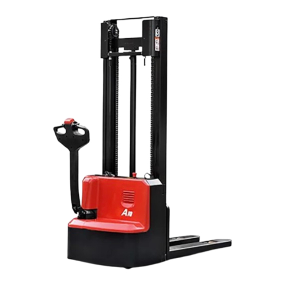
CDD10/12-AMC1
ELECTRIC STACKER
CTD10/12-AMC1
CDD10/12-AMC1-SZ
CTD10/12-AMC1- SZ
CDD10/12-AMC2
CTD10/12-AMC2
OPERATION AND MAINTENANCE
MANUAL
Original Instruction
HANGCHA GROUP CO., LTD.
12 /2022
Table of
Contents
Previous
Page
Next
Page
1
2
3
4
5
Advertisement
Table of Contents
Troubleshooting
Assemble and use notice
71
Common fault and troubleshooting
83
Need help?
Do you have a question about the CDD10-AMC1 and is the answer not in the manual?
Ask a question
Questions and answers
Related Manuals for HANGCHA CDD10-AMC1
Forklifts HANGCHA Mini Range CDD12-A2MJ-SZ Operation And Maintenance Manual
(82 pages)
Forklifts HANGCHA Mini Range CDD15-A2MJ-SZ Operation And Maintenance Manual
(82 pages)
Forklifts HANGCHA Mini Range CDD15-A2MJ-ISZ Operation And Maintenance Manual
(82 pages)
Forklifts HANGCHA CDD15-WS Operating Instructions Manual
Electric stacker (60 pages)
Forklifts HANGCHA A Series Operation And Maintenance Manual
Initial lifting pallet stacker (112 pages)
Forklifts HANGCHA A Series Operation And Maintenance Manual
Electric stacker (119 pages)
Forklifts HANGCHA X Series Operation And Maintenance Manual
Electric pallet jack, pallet stacker (84 pages)
Forklifts HANGCHA CDD16-AC2-L Operation And Maintenance Manual
Initial lifting pallet stacker (112 pages)
Forklifts HANGCHA CDD16-AC2-LI Operation And Maintenance Manual
Initial lifting pallet stacker (112 pages)
Forklifts HANGCHA CDD14-ES Operation Manual
Stand-on pallet stacker (35 pages)
Forklifts HANGCHA CDD12-AC1 Operation And Maintenance Manual
Hi range (124 pages)
Forklifts HANGCHA CDD12/15-A2MA-SZ Operation And Maintenance Manual
Electric stacker (98 pages)
Forklifts HANGCHA CDD10-AMC2 Operation And Maintenance Manual
Electric stacker (117 pages)
Forklifts HANGCHA CDD12-AMC1 Operation And Maintenance Manual
Electric stacker (117 pages)
Forklifts HANGCHA CDD12-AMC1-SZ Operation And Maintenance Manual
Electric stacker (117 pages)
Forklifts HANGCHA XF Series Operation Manual
Internal combustion counterbalanced forklift truck (73 pages)
This manual is also suitable for:
Cdd10-amc2
Cdd12-amc1
Cdd12-amc2
Ctd10-amc1
Ctd10-amc2
Ctd12-amc1
...
Show all
Ctd12-amc2
Cdd10-amc1-sz
Cdd12-amc1-sz
Ctd10-amc1-sz
Ctd12-amc1-sz
Table of Contents
Print
Rename the bookmark
Delete bookmark?
Delete from my manuals?
Login
Sign In
OR
Sign in with Facebook
Sign in with Google
Upload manual
Upload from disk
Upload from URL


Need help?
Do you have a question about the CDD10-AMC1 and is the answer not in the manual?
Questions and answers