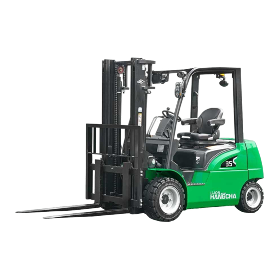
HANGCHA XC Series Operation And Maintenance Manual

HANGCHA XC Series Operation And Maintenance Manual

Electric forklift truck

Advertisement

Quick Links

XC
Series
CPD15/18-XD4-SI16
CPD20/25/30/35-XD4-SI21
CPD20/25/30/35-XD4-SI25
CPD20/25/30/35-XD4-SI26
Electric Forklift Truck
Operation and Maintenance Manual
Original Instruction
HANGCHA GROUP CO., LTD.
05/2020

Advertisement

Table of Contents
loading

Summary of Contents for HANGCHA XC Series

  • Page 1 Series CPD15/18-XD4-SI16 CPD20/25/30/35-XD4-SI21 CPD20/25/30/35-XD4-SI25 CPD20/25/30/35-XD4-SI26 Electric Forklift Truck Operation and Maintenance Manual Original Instruction HANGCHA GROUP CO., LTD. 05/2020...
  • Page 2 FOREWORD Thanks for you purchasing our XC seies Lithium Battery Counterbalanced XC series electric four-wheel forklift truck is our company’s new product. It has the character of small turning radius, beautiful shape, small dimensions, low gravity, good stability, superior performance.
  • Page 3: Table Of Contents

    CONTENT Electric Forklift Truck ....................2 1 Truck introduction ....................1 1.1 General ......................1 1.2 Use occasion and condition ................2 1.3 Appearance and Main Components .............. 3 1.4 Description of display and operating elements ..........4 1.5 Display instrument ..................11 1.6 Lithium battery charging port structure and side door........
  • Page 4 7.3 Periodic replacement of safety-critical parts ..........92 7.4 Forklift used oil and lubrication ..............93 7.5 Replace wheel ..................... 95 7.6 Check and replace fuse ................97 7.7 Check and maintenance of control system assembly ........98 7.8 Bolt tightening torque table ................99 8 The use, install and safety rules of attachment ..........100 8.1 Attachment install ..................100 8.2 Attachment use...................100...
  • Page 5: Truck Introduction

    1 Truck introduction 1.1 General Truck body system Truck frame can remove the lithium battery from the side. The lithium battery drops to – the bottom of the frame. The vehicle length is shorter (80-100mm shorter than the average truck). Drive and brake system Integral drive axle –...
  • Page 6: Electric Forklift Truck

    1.2 Use occasion and condition Truck in this manual is only for handling and transporting loads in short distance. It must be used, operated and maintained according to the information in this manual. Any other uses are outside the design envelope and can lead to injury to persons or damage to equipment and property.
  • Page 7: Appearance And Main Components

    1.3 Appearance and Main Components Load bracket Fork 1、 2、 3、inner gantry 4、outer door Steering wheel Overhead guard frame 5 、 6 、 7 、 Counterweight Driver’s seat 8、 9、rear wheel 10、frame Cover 11、 12、tilt cyliner 13、front wheel 14、lithium battery side door 15、metar...
  • Page 8: Description Of Display And Operating Elements

    1.4 Description of display and operating elements 1、Steering wheel 2、Horn 3、Combination light switch 4、Key switch 5、Lifting lever 6、Tilting lever 7、Water cup holder 8、Emergency disconnect switch 9、Rocker switch 10、Accelerator pedal 11、Brake pedal 12、Parking brake lever 13、Steering column positioning device 14、Travel direction switch...
  • Page 9 Steering wheel [1] Caution The turn signal lever does not  automatically return to the neutral position, reset it by hand. Control truck direction. When the steering wheel is turned right, the forklift will turn to the right; when the steering wheel is turned left, the forklift will turn to the left.
  • Page 10 Key switch[4] backwards angle of lever and the lowering speed can be controlled by tilt forwards angle of the lever. Tilting lever [6] Connect interrupt control current. Remove the key and make sure the truck does not move suddenly. The key switch has two positions: ON and OFF.
  • Page 11 Teacup seat[7] On the right side of the instrument rack, a teacup holder is provided for the driver to place the teacup. Emergency power off switch [8] Turn the power on or off. In case of emergency, press the red mushroom head button to cut off the main power of the vehicle.
  • Page 12 Hand brake handle[12] wheel up and down to ensure that it is locked. Reversing joystick[14] The reversing lever is mounted on the left side of the directional column. Forward file Neutral Reverse gear Pull the handle back, that is, tighten; push the handle forward to relax.
  • Page 13 Fingertip operation(option) another direction. If the direction lever is not in neutral,  Armrest system is composed of armrest when the key switch is turned to ON, a bracket, fingertip, emergency stop button, fault code will be displayed. Return the horn button and wire etc.
  • Page 14 Caution  The multi-way valve is equipped with a front tilt self-locking valve. When the circuit is cut off, the mast cannot tilt In an emergency, press the red mushroom forward even if the lever is pushed head button to cut off the vehicle's main forward.
  • Page 15: Display Instrument

    1.5 Display instrument 1.5.1 Multi-function display Located in the upper right corner of the overhead guard...
  • Page 16 Number Display Number Display It shows current remaining power Body control shortcut key menu It indicates vehicle status: forward or Handbrake Light:The light is on when backward, and no display forneutral gear. the driver operates hand brake. Seat Light:The light is on when the dr There are four working speed: “S”,“P”,“E”...
  • Page 17 Vehicle Control Shortcut Keypad (Optional) icon name Function function key 1 function key 2 function key 3 drive external relay, and specific function is subject to field usage. function key 4 function key 5 Combinatorial key icon name Function Upper shift key In the main interface, press "up key"...
  • Page 18 Menu Structure Introduction Menu adaptation electronic control model: 2.1Description of pump switch menu describe 43C Instrumen ACE2+ACE2 ACE2+HPG Combi-AC2 AC2+HP t meaning Lifting State of lifting Lifting 2 , Lifting Lifting Lifting 1 switch switch Low speed gear Speed 1 switch Speed 1 switch Lifting 1...
  • Page 19 Operator menu 1、 Traction monitoring ---------------------------------------------------(Operator)T.Tester menu describe Remarks ACE2+ ACE2+ Combi AC2+ ACE2 -AC2 Seat switch Seat switch status ON/OFF ● ● ● ● Forward switch Forward gear switch state ON/OFF ● ● ● ● Backdrop switch Back shift switch status ON/OFF ●...
  • Page 20 speed 5 switch status , attachments 5ST SPEED SWITCH ON/OFF ● ● ● ● speed 6 switch status , standby 6STSPEED SWITCH ON/OFF ● ● ● ● cutback switch status CUTBACK SWITCH ON/OFF ● ● ● ● current battery voltage BATTERY VOLTAGE ●...
  • Page 21 1.2 T.Parameter Change scope : 0~100 ACCELERATION 0 S ● ● ● ● scope : 0~100 ACCELERATION 0 P ● ● ● scope : 0~100 ACCELERATION 0 E ● ● ● scope : 0~100 ACCELERATION 0 ● ● ● scope : 0~100 REL.
  • Page 22 scope : 0~100 THROTTLE 0 ZONE ● ● scope : 0~100 THROTTLE X POINT ● ● scope : 0~100 THROTTLE Y POINT ● ● 2 、 Pump Monitor and Set ------------------------------------------------------------------------------------------------(administrator) 2.1 P.Tester ON/OFF seat switch status Handle/Seat SW ● ●...
  • Page 23 Acceler.Delay ● Deceler.Delay ● HYDSpeedCoarse ● HYDSpeedFine ● HYDRoCompens. ● 2ndSpeedCoarse ● 2ndSpeedFine ● 2ndSpeedComp. ● 3rdSpeedCoarse ● 3rdSpeedFine ● 3rdSpeedComp. ● 4thSpeedCoarse ● 4thSpeedFine ● 4thSpeedComp. ● 5thSpeedCoarse ● 5thSpeedFine ● 5thSpeedComp. ● 6thSpeedCoarse ● 6thSpeedFine ● 6thSpeedComp. ● scope :...
  • Page 24 ● ● ● ● the hourmeter is cleared Reset HM after it is changed to 1. 4----------------------------------------------------------------------------------------------------- (administrator)OTHER SET ● ● ● ● Operator password setting Input OperatorPasswordSet password password shall be input twice. ● ● ● ● Administrator password setting AdminPasswordSet ●...
  • Page 25 The multi-function display can display work in this mode in normal work-time. battery power, operating hours, operating CAUTION mode, running speed, fault information, The default mode of the system is P  steering angle, etc., and can display various mode. After each power failure, it warning information in the form of a graphic.
  • Page 26 Empty light [M] key to correspond to S, P, E three operating modes. Example: In the main interface, press the Lights up when the vehicle stall is in neutral key, the main display shows as follows: Battery low capacity indicator[L](Red) When the battery is below 20%, the light is illuminated to remind the user to charge the battery as soon as possible.
  • Page 27 The number “1” indicates closed, the number “0” indicates disconnection, and the and keys can be used to view the up, down, left, and right of the interface. Press to return to the previous interface Press the key after viewing to return to the main menu interface.
  • Page 28: Lithium Battery Charging Port Structure And Side Door

    1.6 Lithium battery charging port structure and side door The charging port of the lithium battery and the side door of the lithium battery are separately introduced here. As the side door and charging port are often used during charging. Detailed lithium battery and charger are described in the following section.
  • Page 29: Lithium Battery Disassembly And Installation

    head to insert or remove. Lithium battery fastening: The lithium on the right side of the lithium battery clamp the truck frame for fastening purpose through the battery clamping device. There are 2 bolts on the clamping device. The heads of the bolts are welded with gaskets. When the bolts are tightened clockwise, the lithium batteries are installed horizontally.
  • Page 30 seat.  Stop the truck to adjust the seat.  It is not allowed to adjust the seat during driving to avoid accidents  Make sure the lever is moved completely to separate the seat structure before forward and rearward adjustment of th e seat and angle adjustment of seat backrest.
  • Page 31 To avoid opening the hood at discretion, a Use left pollex to press the red button (with the snap close is set here. Open the snap close word PRESS) in the socket, it’s untied. first then the hood can be open. ·Check the belt Air spring Check if the bolt that fixed belt is loosened.
  • Page 32 Warning Pedal and handrail for getting on and off When servicing under the hood, be sure There equips with pedal for getting on and off to turn off the key switch to prevent truck both side of the truck, handrails on left electric shock.However, in the case and right overhead guard brace.
  • Page 33 Brake oiler installs in the instrument stand, Steering column positioning device right below the steering wheel. Translucent reservoir enable us check the brake fluid level Adjust and fix steering column according to from outside. needed distance. In order to meet operator’s need, the tilting Caution angle of steering column is adjustable.
  • Page 34: Adjust And Replace Forks

    1.9 Adjust and replace forks Adjust fork distance In order to guarantee safe operation of picking loads, before operation, adjust the fork distance to proper position according to the tray dimension. Procedures: Pull up the fork locating pin upward, and –...
  • Page 35: Ops System(Optional

    OPS in the startup state. OPS abnormal function handling Park the truck in safe place and contact Hangcha agency to check if any below condition is occurred. a. after the driver leaves the seat, the seat indicator light does not light up;...
  • Page 36: Technical Specifications

    1.11 Technical Specifications The technical data given below are standard data. The company reserves the right to make technical changes and additions. CPD20/25/30/35-XD4-SI25 Serial Project CPD20-XD4-SI25 CPD25-XD4-SI25 CPD30-XD4-SI25 CPD35-XD4-SI25 number Rated lifting capacity 2000 2500 3000 3500 Load center distance Standard mast lift height 3000 3000...
  • Page 37 CPD20/25/30/35-XD4-SI26 Serial Project CPD20-XD4-SI26 CPD25-XD4-SI26 CPD30-XD4-SI26 CPD35-XD4-SI26 number Rated lifting capacity 2000 2500 3000 3500 Load center distance Standard mast lift height 3000 3000 3000 3000 Free lift height Mast Tilt angle (front/back) (°) 6/12 6/12 6/12 6/12 Maximum lifting speed mm/s 560/450 560/430...
  • Page 38 CPD20/25/30/35-XD4-SI21 Serial Project CPD20-XD4-SI21 CPD25-XD4-SI21 CPD30-XD4-SI21 CPD35-XD4-SI21 number Rated lifting capacity 2000 2500 3000 3500 Load center distance Standard mast lift height 3000 3000 3000 3000 Free lift height Mast Tilt angle (front/back) (°) 6/12 6/12 6/12 6/12 Maximum lifting speed mm/s 450/350 450/350...
  • Page 39 CPD15/18-XD4-SI16 Serial Project CPD15-XD4-SI16 CPD18-XD4-SI16 number Rated lifting capacity 1500 1800 Load center distance Standard mast lift height 3000 3000 Free lift height Mast Tilt angle (front/back) (°) 6/12 6/12 Maximum lifting speed 460/430 460/420 (no load/full load) Maximum travel speed km/h 17/16 17/16...
  • Page 40: Nameplate And Safety Labels

    1.12 Nameplate and Safety Labels Warnings and notices such as Rated capacities and load centers graph, Warning label and name plate mustbe legible at all times. Replace if necessary. The figure below shows the approximate location of the various markers. Before operating the truck, please understand the meaning of the various symbols.
  • Page 41 编号 名称 Nameplate:Located at the top left of the instrument rack Warning label Warning label:Do not step onto or beneath the load CE label (for CE vehicles) Lift method Lift method Warning label Warning label:Risk of trapping with moving mast Emergency stop switch label Warning label: Measures to be taken when the forklift rolls over.
  • Page 42: The Structure And Stability Of Truck

    1.13 The Structure and Stability of Truck Prevent the forklift to turn over! It is very important for operator to know the truck’s structure and relationship between load and stability. Structure CAUTION The basic structure of the truck is mast (include mast and forks) and body (include tire).
  • Page 43 The max. load and load center CAUTION The load center distance is defined that: the distance between the load center and the fork carriage or the front of the fork carriage. The max. load means the maximum load the truck can charge at the normal load center distance.
  • Page 44 Capacity chart CAUTION The chart given shows the relation between the load center and the weight of loads. Before loading, make sure that the load and the load center distance in the range of capacity chart. If the load’s shape is complex, put the most weightily part on the middle of the forks, and close to the fork carriage.
  • Page 45: Safety Instructions

    mast, front and rear lights, or other high Safety instructions places, be safely secured and take care Only tr ained and accredited operators are not to slip. permitted to operate the forklift truck. Be careful do not be scalded when –...
  • Page 46 speed 5 m/s; maximum relative air may cause the vehicle to tip over. humidity 90% (at 20°C). The truck is not suitable for use in – flammable explosive working environments. – Altitude not exceeds 2000m. Never mount or dismount the forklift while it is in motion.
  • Page 47 17. Hangcha can provide users with a variety 22. Do not stack loads on forks in such a way of attachments including rotating clamps, flat that the top of the load exceeds the backrest clamps, side-shift forks, jibs, etc.
  • Page 48 mast backwards after lowering. Never 27. Be sure to keep your distance from the attempt to tilt the mast with the load roadside or platform edge. elevated. 28. When driving over a ship's gangway or a 24. It is dangerous to travel with the forks bridge, make sure that it is properly secured elevated, regardless of whether loaded or not.
  • Page 49 31. Never lift loads with the truck inclined. Avoid loading and unloading work on a grade. 34. Park the forklift on a level surface and 32. Inspect the surface over which you will apply the handbrake securely. If parking on an run.
  • Page 50 37. The workplace should be equipped with fire extinguishers. Users can also select a vehicle equipped with fire extinguisher. The fire extinguisher is generally installed on the rear leg of the safety frame and is easily accessible. Drivers and managers need to be familiar with the location and use of fire 38.
  • Page 51: Operation And Safety Regulations To Lithium Battery Forklift Truck

    3 Operation and safety regulations to lithium battery forklift truck 1. Contact the manufacturer immediately in case of battery malfunction. Do not open the battery cover for maintenance. 2. Do not reverse charge. 3.Whether charging or discharging, it should be ensured that the battery management system is properly connected and working properly to ensure normal communication of the battery management system.
  • Page 52 Daily charging of lithium battery forklift 1. Charge in time when the forklift meter power shows 1-2 bar (that is, 20%-30% remaining). 2. Turn off the forklift switch power supply and press the emergency stop switch. 3. Close the charger input electric master valve to ensure that the emergency stop switch pops up, the charging device automatically turns on, the power indicator light is on, and the display interface starts automatically.
  • Page 53: Truck Lifting, Carrying And Towing

    4 Truck Lifting, Carrying and Towing 4.1 Lifting Securely fasten wire ropes to the lifting holes in both ends of the outer mast crossbar and to the counterweight hook, and then hoist the forklift with a lifting device. The wire rope fastened to the counterweight end must pass through the gap in the overhead guard, without putting stress on the overhead guard.
  • Page 54: Carrying

    4.2 Carrying Forklift trucks are generally used for loading, unloading and short-distance transportation. They are not designed to be a long-distance mode of transport. A forklift that needs to be transported over a long distance should be transported in a ship, train or a truck having a load capacity over Procedures:...
  • Page 55: Towing

    4.3 Towing Forklift is not permitted to use for daily traction or traction task. Towing pin(13) in the lower counterweight is only used for the following occasions: – Forklift malfunctions on the working road and move the truck urgently. Use when forklift gets into trouble and cannot drive(wheels get stuck in pits etc.) –...
  • Page 56: Lithium Battery

    5 Lithium battery system, mechanical hoisting should be adopted. When moving to the battery system warehouse, the speed should be slow and 5.1 Safety instructions the position should be correct to prevent the extrusion deformation of the battery box. 1.1 It is strictly forbidden to touch the positive When system connected,...
  • Page 57: Instructions For Use

    battery can usually be regarded as the state please contact the vehicle manufacturer for of overcharging. maintenance. Forklift parking environment 3. 7 Explosion: should be kept as dry and ventilated as The battery shell is broken and solid material possible, away from heat sources. 5.5.Maintenance rushes out of the battery and makes sound.
  • Page 58: Size And Weight

    5.7 size and weight 2.0t~2.5t 3.0t~3.5t 2.0t~2.5t 3.0t~3.5t 1.5t,1.8t Item (SI25/26) (SI25/26) (SI21) (SI21) (SI21) Long(L) Width(W) 1084 1064 1084 1064 1014 High(H) Allow the lightest Allow the heaviest...
  • Page 59: Lithium Battery Charging

    5.8 Lithium battery charging The lithium battery special forklift can be equipped with two types of chargers: 1. Titan intelligent charger; 2. Shineng Charger 5.8.1 Titan intelligent charger SLC-80200 Operation instructions for intelligent charger (FAAM battery charger) Start-up interface Start-up interface Click on the icon:...
  • Page 60 The control operation requires password permission. The default password is: 123456. Click on the boot icon: toggle charging control to turn on or off. Click on the purple part of the charging status information bar, enter into the single charging module information display bar.
  • Page 61 Click on the icon: , return to help description interface. Click on the icon:, enter the password modify interface. Click on the icon: , if the password is entered correctly, enter the parameter setting interface, otherwise the password input error is prompted. Please enter it again. Password modification interface Enter in sequence according to the prompt: Enter the user's old password, enter the new password for the first time and enter the new password for the second time.
  • Page 62 Click on the icon: , return to the help description interface. Parameter setting information: rated voltage, rated current and shunt range are related to machine hardware, and must not be arbitrarily modified after the factory. Consult the manufacturer if the above parameters need to be modified. The charging machine number is easy for the user to distinguish, and the user can set it at will.
  • Page 63 1. Choose "turn on" charging control mode. The "CAN" and "485" indicator lights are bright green. 2. DC charging gun and battery connection is normal. 3. "Residual capacity" is less than "allowed to charge the SOC limit" to start charging. 4.
  • Page 64 Power check Make sure that AC input zero wire and DC output positive and negative electrode wiring are correct, and that there is no short circuit in input and output; The input voltage and frequency are normal; At any time in the state of electricity.Offline online charging lines can not be connected at the same time.
  • Page 65 5.8.2 Shineng Charger a. Summarize CZC7SI series intelligent charger uses high-performance embedded charging control unit to control the charging current. Main circuit module designed by parameters optimization provides continuously adjustable charging current for various batteries and lithium batteries to meet various charging process requirements.
  • Page 66 (7)The vertical plane is inclined no more than 5 degrees and there is no strong vibration and impact. c. Main technical parameters CZC7SI-D Model 100V/200A Item Parameter Rated input power Three phase 380V 50Hz Charger rated input power 21.3 Charger input current 32.3 Charger max.
  • Page 67 e. Instructions e.1. Panel schematic Desk type charger Power switch LCD Touch screen Charging state indicator Vertical type charger Power switch——Turn the grid power on or off. (Desk type charger) LCD Touch screen——The human-machine interface of the charger displays the parameters and status of the charging process of the charger and the operation of setting parameters of the charger.
  • Page 68 e.2. LCD touch screen description Clock display Charger type Charging state display Start/stop button Charging process parameterdisplay Setbutton area “Start/Stop” button: The button for charger start/stop charging controls the start and  stop of the charger. “Charging state display”: Display various states prompt texts corresponding to the ...
  • Page 69 welcome click to enter e.4. Operation steps of charging process 1) Turn on the charger input power. 2) Connect the charger and battery charging plug or charging gun. 3) Turn on the power switch of the charger, and the “LCD touch screen” on the panel will be powered on.
  • Page 70 parameter setting. Click "←" to cancel the number of one setting. Click " . " to set the decimal point of the number. e.6. Fault description and corrections It must be repaired by professional electrical technicians. Fault type Fault phenomenon Corrections Battery 1) Check the battery cable...
  • Page 71 or corrosion. Charging procedures: Stop the truck, turn off the key switch, CPD20/25/30/35-XD4-SI25 and the truck is disconnected. Close the charger main input valve, make sure the emergency stop button bounce, the charger turns on automatically, the indicator illuminates, and the display screen starts automatically.
  • Page 72 charging gun out. If it needs stop charging without being fully charged, first press the pause button, wait until the charge current is reduced to 0A, and then press charging gun lock and pull the charging gun out. Insert the charging gun to the charger lay-down position, and pull down the charger main input valve.
  • Page 73 Cautions for use and maintenance of lithium ion battery Basic requirements for battery use Under any circumstances, when testing or using the battery, the terminal voltage of the single battery must be tested in real time. It is strictly forbidden to test the battery pack in series without a management system or a protection board to avoid overcharging or overdischarging of the battery;...
  • Page 74 5. Do not operate an electric vehicle equipped with a lithium battery in an environment where the temperature exceeds 55 °C; if the power battery system is below -25 °C, the power battery system needs to be self-heated above -10 °C to operate the vehicle; 6.
  • Page 75 4、Normal charging, abnormal discharge or normal discharge, abnormal charging.The protective plate is broken.Solution: the protection plate needs to be replaced. Chapter VIII Emergency Preparedness Extreme anomalies that may occur during battery operation:In the process of use, users should establish a good sense of safety prevention, prohibit illegal operation strictly, avoid battery system abuse (overcharge, over-discharge, short-circuit, extrusion, puncture, environmental overheating, high-current discharge, etc.).Possible anomalies in the battery system during charging and use are as follows:...
  • Page 76: Instructions

    6 Instructions 6.1 Running-in of the new truck We recommended operating the machine under light load conditions for the first stage of operation to get the most from it. Especially the requirements given below should be observed while the machine is in a stage of 100 hours of operation. Must prevent the new battery from over discharging when early used.
  • Page 77: Check And Adjust Before Operation

    6.2 Check and adjust before operation For the safe operation of forklift, do relevant check and adjustment to the forklift before operation. Warning If there is damage or potential risk on forklift or attachment after check, then do not  operate the forklift before repairing.
  • Page 78 Check tire pressure(Pneumatic tire only) Turn tire valve cap counter clock-wise and remove it. Using a tire pressure gauge, measure the inflation pressure, and adjust it to the specified pressure, if needed.After confirming leakage free, screw the nut cap, check if the ground surface or side of the tire damaged, and rim transformed.
  • Page 79 surfaces, otherwise it will damage Procedures: the paint. Depress the brake pedal and check that – When adding brake fluid, avoid  it moves freely without jamming. getting dust and water in the The correct braking distance without a – reservoir.
  • Page 80 with your thumb to check whether the tension between the left and right chains is identical. – Tension adjustment: loose the lock nut and turn the adjuster nut to adjust the chains so that they both have the same tension, then tighten the lock nut. Mast and fork check Forks are not cracked or bent, and that –...
  • Page 81: Driving Truck

    6.3 Driving truck welcome screen, and all 6 indicators Driving and Operation are lit.During this time the forklift WARNING could not drive and lift. If the direction Before operating the truck, check all  controls and warning devices for switch or accelerator pedal or hoist proper operation.
  • Page 82 CAUTION CAUTION Don’t dismount from the moving  Decelerate the truck in the situations truck, never jump from the truck. following: Don’t parking the truck on the  Turning;  working road. Close the goods or pallet;  Close the deposit area; ...
  • Page 83 After making sure the forks leave the – load, lower the forks to the basic position (15cm to 20cm off the ground). – Tilt the mast backwards. CAUTION Decelerate the truck in the situations following: Turning;  Close the goods or pallet; ...
  • Page 84 Check after operation CAUTION Clean and check the truck after operation: If the forks are hard to be fully  – Damage or leakage. inserted, following Add grease if necessarily. – procedure: Move forward and insert Check the tire if it is damaged or inset –...
  • Page 85: Maintenance

    Inspection and maintenance are often easily overlooked. Early detection enables problems to – be settled in a timely manner. Use original Hangcha Group spare parts. – Do not use different types of oil when changing or topping up oil. –...
  • Page 86 Caution No open flames.  Turn off the keyswitch and disconnect the battery plug before carrying out any  servicing or maintenance. (except when carrying out certain obstacle checks). Clean electrical parts with compressed air. Do not clean with water. ...
  • Page 87: Periodic Maintenance Schedule

    7.2 Periodic maintenance schedule 〇 —check, correct, adjust ×—replace D—Daily; W—Weekly; M—Monthly; T—Trimonthly; S—Semiannually; Y—Yearly Electrical System lithium battery Service Item Tool required (8 h) (40 h) (166 h) (500 h) (1000h) (2000h) Lithium battery installation and 〇 〇 〇 〇...
  • Page 88 Controller Service required Item Tool (8 h) (40 h) (166 h) (500 h) (1000h) (2000h) Check condition of 〇 〇 〇 contacts Check mechanical movement of 〇 〇 〇 contactors Check pedal microswitches are 〇 〇 〇 functioning properly Check condition of connections between motor, 〇...
  • Page 89 Left right Combinat steering switch 〇 〇 〇 〇 operation switch (steering, Light stalls and 〇 〇 〇 〇 lighting) work conditions Work and 〇 〇 〇 〇 〇 horn installation Lights Work and 〇 〇 〇 〇 〇 installation light bulb Reversin Work and...
  • Page 90 Transmission system Service Item Tool required (8 h) (40 h) (166 h) (500 h) (1000h) abnormal 〇 〇 〇 〇 〇 noise Check 〇 〇 〇 〇 〇 leakage For the first 3 months, Change oil every 6 months thereafter Check for hub bearing...
  • Page 91 Steering System Service required Item Tool (8 h) (40 h) (166 h) (500 h) (1000h) (2000h) Check play 〇 〇 〇 〇 〇 〇 Check axial looseness 〇 〇 〇 〇 〇 〇 Check radial 〇 〇 〇 〇 〇 〇...
  • Page 92 Braking system Service required Item Tool (8 h) (40 h) (166 h) (500 h) (1000h) (2000h) Freeplay Ruler 〇 〇 〇 〇 〇 〇 Pedal stroke 〇 〇 〇 〇 〇 〇 Operation 〇 〇 〇 〇 〇 〇 Check for air in 〇...
  • Page 93 Hydraulic system Service Item Tool required (8 h) (40 h) (166 h) (500 h) (1000h) (2000h) Check oil level, × × 〇 〇 〇 〇 change oil Clean oil filter 〇 〇 Clear foreign 〇 〇 bodies Loose 〇 〇 〇...
  • Page 94 Lifting system Service required Item Tool (8 h) (40 h) (166 h) (500 h) (1000h) Check chain tension, check for deformation, 〇 〇 〇 〇 〇 damage and corrosion Lubricate chain 〇 〇 〇 Riveting pins and loose- 〇 〇 〇...
  • Page 95 Wear and damage of mast support bearing 〇 bushes Looseness of mast Testing 〇 〇 support cover bolts hammer (first time only) Looseness of lift Testing 〇 cylinder piston rod head 〇 hammer (first time only) bolts and plate bolts Cracking and damage of welding on inner 〇...
  • Page 96: Periodic Replacement Of Safety-Critical Parts

    7.3 Periodic replacement of safety-critical parts Some parts are difficult to inspect during periodic maintenance. Therefore, in order to further – improve safety, users should carry out periodic replacement of the parts listed in the following table. If any of these parts are found to be damaged or faulty before they are due for replacement, –...
  • Page 97: Forklift Used Oil And Lubrication

    7.4 Forklift used oil and lubrication Fuel charge Code Description Specification Remark (L) Common environment:L-HM32 Hydraulic oil 35~65 Hydraulic oil tank Refrigerator/cold environment:L-HV32 Choice HZY3 brake fluid(Add before Brake fluid ≈1.0 Braking oiler delivery) or DOT3 brake fluid Lubricating Lubricating General purpose lithium surface or grease...
  • Page 98 Replace hydraulic oil Hydraulic oil should be changed every half year Procedures: Park the truck on level ground – Tilt the mast backward to the end and drop – the forks on the ground; – Remove the rubber pad from baseboard. Remove rear baseboard.
  • Page 99: Replace Wheel

    7.5 Replace wheel Warning Replace in pairs in time when tires wear to limit Use proper tools like wedge or  or is damaged. After running for 10hours with hardwood base to fix to prevent replaced tires, check if the wheel nuts tighten or not.
  • Page 100 block. – Release hub nut, remove the wheel and replace new tire. Warning Do not take out wheel nuts before the  rear wheels leave the ground. Install the new tire on the hub, and – screw down the hub nut symmetrically Place a solid wood block under the truck –...
  • Page 101: Check And Replace Fuse

    7.6 Check and replace fuse Fuse parameter list Fuse position Fuse list Position Capacity Application component DC converter 80V power output end 24V power output end 1 Flasher, 24V power output end 2 Horn, 24V power output end 3 24V 4 output end 4 Headlamp, 24V output end 5 24V Power reserve Emergency stop button...
  • Page 102: Check And Maintenance Of Control System Assembly

    7.7 Check and maintenance of control system assembly Procedures: Park the forklift. – Open the right door and remove the – battery plug. – Open counterweight cover plate. Expose the control system assembly elements, then check, replace and adjust. Description Control circuit Specification controller...
  • Page 103: Bolt Tightening Torque Table

    The magnetic field and magnetic radiation of the environment have a certain influence on the – normal operation of the inverter, and the long-term influence may damage the controller. Therefore, keep away from magnetic fields and magnetic radiation. 7.8 Bolt tightening torque table Unit:N·m Grade Bolt diameter...
  • Page 104: The Use, Install And Safety Rules Of Attachment

    8 The use, install and safety rules of attachment HANGCHA will choose attachment that in accordance with International standard ISO2328 Forklift pothook fork and installation size of carriage, such as sideshifters, fork positioner, rotator, push/pull and clamp ect. sideshifterfork positionerrotatorpush/pull...
  • Page 105: Check And Maintenance

    of cargo and ground is less than 300mm and mast incline back. – The weight of cargo couldn’t exceed the limited value of combination carrying capacity of forklift and attachment. It is not allowed that partial load at high position. It is a short time work for attachment with side-shifter.
  • Page 106: Related Safety Instruction And Standard (For Trucks Exporting To Europe Or Option)

    9 Related safety instruction and standard (for trucks exporting to Europe or option) The model by CE certification which according to the following instruction and standard: The results meet the requirements of Directive 2006/42/EC of the European Parliament and of the council on the approximation of the laws of the Member States relating to machinery、2000/14/EC of the European Parliament and of the council on the approximation of the laws of the Member States relating to the noise emission in the environment by equipment for use outdoors、...
  • Page 108 Maintenance record Date Service content Serviceman...
  • Page 109 HANGCHA GROUP CO. , LTD. ■Address For: OVERSEAS USERS ■Address: 666 Xiangfu Road, Lin'an, Hangzhou,Zhejiang,China ■Fax: 0086-571-889267890086-571-88132890■ ZIP:311305 ■Web: http://www.hcforklift.com■E-mail: sales@hcforklift.com...

Table of Contents