
Subscribe to Our Youtube Channel
Related Manuals for HANGCHA CDD15-WS


Summary of Contents for HANGCHA CDD15-WS
- Page 1 CDD15-WS Electric stacker Operating instructions Original Version No.: STX/CDD15-WS/2302...
- Page 2 Foreword The present ORIGINAL OPERATING INSTRUCTIONS are designed to provide sufficient instruction for the safe operation of the industrial stacker. The information is provided clearly and concisely. Please read and follow all warnings before operation. Please confirm that the safety parts are always intact.
-
Page 3: Table Of Contents
Content A Correct use and application ......................1 B Stacker Introduction ......................... 2 Application............................. 2 General .............................. 1 Use according to regulations ......................1 Precautions for using cold storage stackers ................2 Assemblies............................. 3 Summary ............................3 Main part name........................4 Standard Version Specifications ..................... - Page 4 3.3.2 Travelling, Steering, Braking ....................27 3.3.3 Collecting and depositing loads ....................28 Parking the stacker securely ...................... 29 Deposit the stacker ........................29 3.5.1 Deposit the stacker for long time .................... 29 3.5.2 Start running after deposit for a long time ................29 F Maintenance............................
-
Page 5: A Correct Use And Application
Correct use and application The “Guidelines for the Correct Use and Application of Industrial stackers” are supplied with the stacker. The guidelines are an integral part of the operating instructions and must be observed. National regulations apply in full. The stacker described in the present operator manual is an industrial stacker designed for lifting and transporting load units. -
Page 6: B Stacker Introduction
Stacker Introduction Application 1.1 General This manual only applies to electric stackers, it is designed for use on level floors to lift and transport palletized goods. Open bottom pallets or roll cages can be lifted. The capacity can be obtained from the data plate. The capacity with respect to lifting height and load centre of gravity is indicated on the capacity plate. -
Page 7: Assemblies
This operation manual introduces the electric stacker, which is suitable for use in places with low work intensity and continuous working time not exceeding 1 hour. Users can obtain related information such as rated load from the product model. CDD15-WS Meaning Economic stacker... -
Page 8: Main Part Name
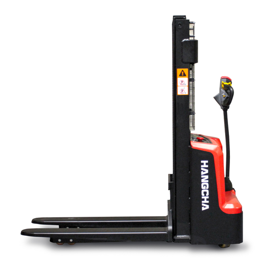
Main parts introduction Item No. Type Parts name ○ Mast ● Cylinder assy. ● Accelerator assy. ● Handle control box ○ Charging plug ● Handle tube ● Bottom cover ● Drive unit assy. ● Universal wheel assy. ● Upper cover ●... -
Page 9: Standard Version Specifications
Standard Version Specifications The technical data provided below are all standard data. Our company reserves the right to make technical changes and supplements. Standard technical data Model No. CDD15-WS Drive Battery Powered Operator type Pedestrians Load capacity/rated load 1500 Load centre distance... -
Page 11: Norms
EN norms Noise emission: <75 dB(A) in accordance with EN 12053 as harmonised with ISO 4871. The noise emission level is calculated in accordance with standard procedures and takes into account the noise level when travelling, lifting and when idle. The noise level is measured at the driver’s ear. -
Page 12: Stacker Data Plate
Item Description Operation warning Handle warning Charging warning Attachment point for lifting by crane "Do not stand on/under the fork" warning Load chart label Switch ON/OFF warning label stacker data plate Stacker data plate Item Description Item Description Model No. Year of manufacture Net weight excl. -
Page 13: C Transport And Commissioning
Transport and Commissioning Lifting by crane The stacker is designed for short-distance lifting, lowering and transporting load units, not suitable for long-distance travel. If needed, the stacker must be transported by using lifting device or platform to place on stacker or trailer. ... -
Page 14: Using The Stacker For The First Time
Using the stacker for the first time Operate the stacker only with battery current. Rectified AC current will damage the electronic components. The battery leads (tow cable) must be less than 6m in length. It is forbidden to raise loads if the stacker is operated via a tow lead with an external battery. To prepare the stacker after delivery or after transport, proceed as follows: –... -
Page 15: D Battery Maintenance, Charging & Replacement
Battery Maintenance, Charging & Replacement This stacker is equipped with two maintenance-free batteries. The battery has the longest lifespan when the temperature is between 25℃~30℃. Lower temperatures decrease the available capacity of the batteries, while higher temperatures shorten their lifespan. Each battery weighs approximately 25kgs. -
Page 16: Battery Storage
Weekly Visual inspection after recharging for signs of dirt and mechanical damage. If the battery is charged regularly with a IU characteristic curve an equalising charge must be carried out. Monthly At the end of the charge the voltages of all cells or bloc batteries should be measured with the charger switched on, and recorded. -
Page 17: Charging The Battery
– Charger matching: The matching of charging parameters of the battery has a significant impact on the performance and lifespan of the battery, so users should choose a high-quality charger with the same charging parameters as the original charger when replacing the charger. -
Page 18: Battery Charging
Battery charging Charging steps: – Drive the stacker to appointed charging place, park the stacker and render if safe. – Open the cover(2) of holder and pull out the charging plug (1), then insert it into a suitable power socket. –... - Page 19 LED display Indicator label Red light flashes every one seconds.Battery level<80%: Yellow light flashes every one Charging:Red light flicker: Battery Indicator Full:Green light is glowing: seconds.Battery level>80%: Green light flashes every one seconds.Battery level 100% Green and red light will be alternately flashes Empty load Over voltage,Over current: Red Green Red - - - Ambient temperature is too high or too low...
-
Page 20: Battery Changed And Installation
Common fault and solution Indicator State Fault indication Solution “-”show pause Check these happen:the connection of battery and charger is Red Green Without load loose, the battery reversed, or the battery voltage is too low. Red-Green-Red Over voltage or over If the error opens again after restart - - - current... -
Page 21: Battery Charge / Discharge Indicator
When replacing a battery always use the same battery type. Extra weights must not be removed and must remain in the same position. – Installation is in the reverse order of operations. When reinstalling the battery, heed the required installation position and make sure the battery is connected correctly. After installing the battery again, check all cables and plug connections for visible signs of damage. -
Page 22: E Operation
Operation Safety Regulations for the Operation of Stackers Driver authorisation: The stacker may only be used by suitably trained personnel, who have demonstrated to the proprietor or his representative that they can drive and handle loads and have been authorised to operate the stacker by the proprietor or his representative. -
Page 23: Display And Control
Parts name Type Function ● Handle tube Control steering and braking of the stacker. Interrupt circuit, stop all electrical functions. The stacker is forced to Emergency stop ● switch brake. ● Display the operating status of the built-in charger. Flashing red light: charging in progress. Charging LED Green light always on: charging completed or waiting for battery. -
Page 24: Display
When the safety protection function is triggered by pressing this button, Emergency the stacker immediately travels in the direction of the fork for about 3 ● reverse button seconds, and the parking brake is activated. The stacker can only be started again when the driving switch is restored to its initial position. - Page 25 Variable Speed Control on Lifting/Lowering – We patented intelligent handle and control system – This handle control box is equipped with an advanced feature known as "infinite speed control" for both lifting and lowering operations. – This innovative function allows for continuous and seamless adjustments to the lifting and lowering speeds, without being limited to predefined speed settings.
- Page 26 Emergency stop switch[2] Press this switch, power is off. Press it when emergency or no use. If re-start needed, pull upward. Key switch assy.(with keys) [4] Turn on the key switch, and the power is on. Turn off the switch, and the power is off. Turn off the key switch before charging.
-
Page 27: Operating
Emergency reverse button[8] - This switch is at the head of control lever, once touch this button, the stacker moves forward. It is used to protect people from being clamped by the control handle. - This switch is also called belly switch. Travel switch[9] ●... - Page 28 3) Front/rear wheel and balance wheel check Check the wheel and see whether there is any crazed, damaged, or abnormal wearing. Check the wheel fasteners for looseness.And inspect whether there is rope on the wheel. 4) Check front fork and linkage mechanism Check the fork and linkage mechanism, see whether bending or crazed.
-
Page 29: Starting Up The Stacker
Steering system Left or right turn the handle to make the stacker run around 3 turns, and then check if the steering system is normal. Check chain tensity – Lift forks up 10~15cm. – Press the middle of the chain and see if the left &... -
Page 30: Using The Stacker
Travel routes and work areas: Only use lanes and routes specifically designated for stacker traffic. Unauthorised persons must stay away from work areas. Loads must only be stored in places specially designated for this purpose. Driving conduct: The driver must adapt the travel speed to local conditions. The stacker must be driven at slow speed when negotiating bends or narrow passageways, when passing through swing doors and at blind spots. -
Page 31: Travelling, Steering, Braking
Never carry passengers. Emergency Stop – Pull down the emergency disconnect switch(2), all electrical functions are deactivated. Automatic braking Automatic braking occurs when the tiller is released – the tiller automatically sets itself to the upper brake zone (B1 & B2). If the tiller moves slowly to the brake zone(F), the cause of this fault must be rectified. -
Page 32: Collecting And Depositing Loads
Plugging: – You can set the travel switch (9) to the opposite direction when traveling. – The stacker braked regeneratively until it starts to move in the opposite direction. Braking with the Coasting Brake: If the travel switch is set to 0, the stacker automatically brakes regeneratively. In hazardous situations set the tiller to the brake position. -
Page 33: Parking The Stacker Securely
When you leave the stacker it must be securely parked even if you only intend to leave it for a short time. Drive the stacker to safe area or appointed area. Do not park the stacker on a slope. The load forks must always be lowered to the ground. -
Page 34: F Maintenance
F Maintenance The servicing and inspection operations contained in this chapter must be performed in accordance with the intervals indicated in the servicing checklists. Any modification to the forklift truck assemblies, in particular the safety mechanisms, is prohibited. The operational speeds of the truck must not be changed under any circumstances. -
Page 35: Servicing And Inspection
Electrical System: Only suitably trained personnel may operate on the truck’s electrical system. Before working on the electrical system, take all precautionary measures to avoid electric shocks. For battery-operated trucks, also de-energise the truck by removing the battery connector. Welding: To avoid damaging electric or electronic components, remove these from the truck before performing welding operations. -
Page 36: Maintenance Checklist
〇—Check, revise, adjust × —Replace Battery Service Service required Tools item 〇 〇 〇 〇 〇 Battery level 〇 〇 〇 〇 〇 Terminal looseness 〇 〇 〇 〇 〇 Looseness of connecting wire 〇 〇 〇 〇 Cleanness of the battery surface 〇... - Page 37 Driving system Service Service required Tools item 〇 〇 〇 〇 〇 Check for noise 〇 〇 〇 〇 〇 Check for leakage Add lubricating grease 2years 〇 〇 〇 〇 Bearing lubrication 〇 〇 〇 〇 〇 Check if the steering flexible 〇...
- Page 38 Lifting assembly Service Service required Tools item 〇 〇 〇 〇 〇 Check chain for tension, damage or rust 〇 〇 〇 Add lubrication for chains Chain & 〇 〇 〇 Check chain wheel for deformation or damage chain wheel 〇...
-
Page 39: Oil And Lubrication
Oil and lubrication Filler plug for hydraulic oil Lubrication part Hydraulic oil drain plug Code Designation Mark, code Remark Normally: L- HM32 Hydraulic oil Hydraulic system High and cold environment:L- HV32 Grease Automobile general 3 # lithium base lubricant Nozzle and lubrication Grease Shell Alvania R3 lubricating grease Gearbox... -
Page 40: Replace The Key Safe Parts Periodically
Only use clean containers when filling up with consumables. Do not mix consumables of different grades. The only exception to this is when mixing is expressly stipulated in the operating Manual. Avoid spillage. Spilled liquids must be removed immediately with suitable bonding agents and the bonding agent / consumable mixture must be disposed of in accordance with regulations. -
Page 41: G Structure, Principle And Maintenance
F Structure, Principle and Maintenance Driving system This stacker adopts a hub type drive unit (see Figure 2-1). The drive unit has the characteristics of high efficiency, large transmission ratio range, compact structure, and small volume. -
Page 42: Working Principle
The transmission line of the driving unit is: the driving unit drives the driving gear directly through the motor. The transmission sequence is part 15 (drive motor) → part 13 (driving gear) → part 4 (driven gear) → part 3 (gear shaft) → part 22 (inner gear ring) to drive the drive wheel output. -
Page 43: Fault And Troubleshooting
– The normal operating oil temperature ≤70℃。 – The drive unit is a maintenance free drive device. If lubricating grease needs to be added, the drive unit must be removed and added from the top. – The injection amount of lubricating grease (Shell Alvania R3 Lubricant) is 2/5-2/3 of the inner cavity. - Page 44 – Overloading is strictly prohibited. – It is strictly prohibited to coexist with strong magnetic objects. – The input voltage level needs to be ensured to be correct. – If any abnormal odor is found during use, the motor should be immediately stopped for inspection.
- Page 45 Motor fault diagnosis Fault diagnosis Probably cause All copper sheets turn Incorrect brush pressure black Short circuit between reversing plates The reversing pads are Armature coil short circuit grouped in a certain order and blackened Poor welding or open circuit between the commutation plate and the armature coil The reversing pad turns Displacement of commutator centerline...
-
Page 46: Electromagnetic Brake
1.6 Electromagnetic brake The brake used in this vehicle is a spring loaded electromagnetic brake. This brake is a single disc brake with dual friction surfaces. By using pressure springs, a strong braking torque can be generated in a power off state, and electromagnetic effects can release the brake. 1.Brake mounting screws 2.Stator assembly 3.Friction brake pads... -
Page 47: Brake Installment
1.6.2 Brake installment – Place the flat key (13) into the keyway on the motor shaft (9), press the shaft sleeve (4) onto the shaft (9), and secure it with an internal circlip (14). – Install the friction disc (5) onto the motor end face using three friction disc mounting screws (12). -
Page 48: Maintenance
1.6.3 Maintenance – If work in high temperature environment for long time, please prevent rust, it may influence use if there is rust on the suction surface. – Do not touch the friction surface with hand, no oil stain, otherwise it cannot reach the maximum torque. -
Page 49: Braking Principle Diagram
– Use a feeler gauge to check if the brake air gap "Z" meets the requirements. – Adjust the three installation screws and hollow screws according to the diagram, adjust the air gap "Z", and then tighten the brake installation screws. In general working condition, the first air gap adjustment should proceed after brake working for 1500~2000hours, frequency of air gap adjustment is every 6 months. -
Page 50: Common Fault And Troubleshooting
1.6.6 Common fault and troubleshooting Fault Probable cause Corrective action Power is obstructed Connect Too low exciting voltage Check voltage and adjust. Brake does Improper air gap Adjust air gap not work Stator coil breaks Replace stator Oil dirt mixed in Clean oil dirt Install the switch to the DC circuit after Switch installed to AC circuit... -
Page 51: Hydraulic System
Hydraulic system Hydraulic system is mainly composed of hydraulic unit, lifting cylinder and rubber tube etc. 1. Circlip 2. Flat washer 3. Cylinder retainer plate Screw M8x25 Cylinder assy. 6. Oil return pipe connector Oil return pipe High-pressure oil pipe connector Screw M12X25 High-pressure oil pipe .Screw M10X25... -
Page 52: Hydraulic System Working Principle
Hydraulic system working principle – Press the lifting button on the control box to start the oil pump motor and transmit torque from the motor to the gear pump through the transmission shaft. The gear pump sucks hydraulic oil out of the oil tank and enters the lifting cylinder through a one-way valve. High pressure oil drives the piston rod to move, thereby driving the fork and load up. -
Page 53: Hydraulic Unit
Hydraulic unit The stacker adopts combined hydraulic unit(Fig.2-7), and is composed of DC motor, coupling, valve board and valves, oil pump and fuel tank etc. Rated power 2.2 kW Rated voltage 24 VDC Hydraulic motor Working system S2=1.5min Working system S3=4%ED Rotation direction Rotate in counterclockwise... -
Page 54: Hydraulic System Fault Diagnosis And Correction
Hydraulic System Fault Diagnosis and Correction Fault Possible reasons Corrective action Low oil level in the fuel tank Fill to the specified oil level No oil output from the Clean the oil circuit and fuel tank. If the hydraulic oil oil pump Filter clogged is dirty, replace it... -
Page 55: Principles Of Electrical System
Electrical Schematic diagram... -
Page 56: Motor Controller
Detailed description of the controller port definition (from the perspective of the direction of the plug in line and the outline) Logic Lowering Lowering Lowering power Horn solenoid solenoid solenoid 14V- Brake+ supply output valve-3 valve-2 valve-1 24V+ Hydraulic Lifting Drive motor Temperature motor... -
Page 57: Handheld Programmer
● Do not allow water to enter the product! ● Do not operate with power on! ● Do not reverse polarity! ● Do not short circuit the motor! 3.2.2 Handheld programmer ► The programmer is for easy maintenance and service of the truck. ►... - Page 58 Controller Controller temperature is too high After a certain period of rest, overheating Err 23 TEMP0_HI_ERROR and used too frequently. use it again. protection Motor overheat The temperature of drive motor is After a certain period of rest, Err 24 MHEAT_LIMIT_FAULT current limiting too high and used too frequently.
-
Page 59: Attachment: List Of Bolt Tightening Torques
Unit: Nꞏm Class Bolt diameter 4 ~ 5 5 ~ 7 6 ~ 8 9 ~ 1 2 1 0 ~ 1 2 1 2 ~ 1 5 1 4 ~ 1 8 2 2 ~ 2 9 2 0 ~ 2 5 2 5 ~ 3 1 2 9 ~ 3 9 4 4 ~ 5 8... - Page 60 Maintenance Date Repair and maintenance content personnel...
Need help?
Do you have a question about the CDD15-WS and is the answer not in the manual?
Questions and answers