Table of Contents
Advertisement
Quick Links
ELECTRIC STACKER
OPERATION AND MAINTENANCE
CDD12/15-A2MA-SZ
CDD12/15-A2MA-ISZ
CDD12/15-A2MA-SZF
CDD12/15-A2MJ-SZ
CDD12/15-A2MJ-ISZ
CDD12/15-A2MJ-SZF
CDD12/15-A2MAS-SZ
CDD12/15-A2MAS-ISZ
CDD12/15-A2MJS-SZ
CDD12/15-A2MJS-ISZ
CDD12/15-A2MJ2-SZ
CDD12/15-A2MJ2-ISZ
CDD12/15-A2MC2-SZ
CDD12/15-A2MC2-ISZ
MANUAL
Original Instruction
HANGCHA GROUP CO., LTD.
3/2023
Mini Range
CTD12/15-A2MA-SZ
CTD12/15-A2MA-ISZ
CTD12/15-A2MA-SZF
CTD12/15-A2MJ-SZ
CTD12/15-A2MJ-SZF
CTD12/15-A2MJ-ISZ
CTD12/15-A2MJ2-SZ
CTD12/15-A2MJ2-ISZ
CTD12/15-A2MC2-SZ
CTD12/15-A2MC2-ISZ
Advertisement
Table of Contents
Troubleshooting

Related Manuals for HANGCHA CDD12/15-A2MA-SZ


Summary of Contents for HANGCHA CDD12/15-A2MA-SZ
- Page 1 Mini Range CDD12/15-A2MA-SZ CTD12/15-A2MA-SZ ELECTRIC STACKER CDD12/15-A2MA-ISZ CTD12/15-A2MA-ISZ CDD12/15-A2MA-SZF CTD12/15-A2MA-SZF CDD12/15-A2MJ-SZ CTD12/15-A2MJ-SZ CDD12/15-A2MJ-ISZ CTD12/15-A2MJ-SZF CDD12/15-A2MJ-SZF CTD12/15-A2MJ-ISZ CDD12/15-A2MAS-SZ CTD12/15-A2MJ2-SZ CDD12/15-A2MAS-ISZ CTD12/15-A2MJ2-ISZ CDD12/15-A2MJS-SZ CTD12/15-A2MC2-SZ CDD12/15-A2MJS-ISZ CTD12/15-A2MC2-ISZ CDD12/15-A2MJ2-SZ CDD12/15-A2MJ2-ISZ CDD12/15-A2MC2-SZ CDD12/15-A2MC2-ISZ OPERATION AND MAINTENANCE MANUAL Original Instruction HANGCHA GROUP CO., LTD. 3/2023...
- Page 2 FOREWORD Thank you very much for purchasing the A series mini range electric stacker of Hangcha Group . The A series 1.2 and 1.5 tons mini second-generation stacker trucks are a new generation of products developed by Hangcha for warehousing and logistics applications. They adopt the latest permanent magnet drive technology, have advanced performance, comfortable operation, safe and reliable, and low maintenance costs.
-
Page 3: Table Of Contents
Content Part Ⅰ:Operation and Maintenance ................... 1 Notice for use ..........................1 1.1 General ............................1 1.2 Use as required ......................... 1 1.3 Normal service condition ......................2 1.4 Attachment installation or modification to the truck ..............3 1.5 Precautions for the use of cold storage vehicles .................4 Truck Introduction ........................ - Page 4 9.1 Maintenance general .......................38 9.2 Periodic maintenance schedule ....................39 9.3 Truck used oil and lubrication ....................44 9.4 Replace hydraulic oil ....................... 45 9.5 Replace wheels ........................46 9.5.1 Replace drive wheel ........................46 9.5.2 Replace load wheels .......................47 9.6 Replace the key safe parts periodically .................. 48 10 Relevant safety directive or standard (CE or optional) ..............
-
Page 5: Part Ⅰ:operation And Maintenance
Part Ⅰ:Operation and Maintenance Notice for use 1.1 General Truck in this manual is only for lifting and transporting loads. It must be used, operated and maintained according to the information in this manual. Any other uses are outside the design envelope and can lead to injury to persons or damage to equipment and property. -
Page 6: Normal Service Condition
1.3 Normal service condition Truck use occasion and specified conditions: – Used in specified area as factory, tourist attraction and recreation place. – Used on the flat ground, that is fixed and owns enough carrying capacity(protect operation and lifting). – It's prohibited to operate across the raised or hollow as the small wheel diameter may easily cause truck tipping over. -
Page 7: Attachment Installation Or Modification To The Truck
1.4 Attachment installation or modification to the truck Without authorization by the manufacturer, it is not allowed to modify the truck privately. The mounting or installation of any attachments which will interfere with, or supplement, the functions of the truck is permitted only after written approval by the manufacturer has been obtained. -
Page 8: Precautions For The Use Of Cold Storage Vehicles
1.5 Precautions for the use of cold storage vehicles – Use special oil products for cold storage and regular maintenance and replacement. – All cold storage trucks cannot be shut down and parked in the cold storage, otherwise the hydraulic system and electrical system may be damaged. –... -
Page 9: Truck Introduction
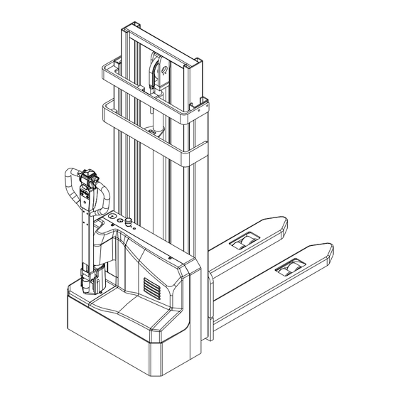
Truck Introduction 2.1 General A series mini range electric stacker described in this manual should work under low working strength and its continuous working time should not surpass one hour. Users can get relevant information as rated load from the product model. Model CDD12-A2MJ-ISZ as an example: CDD12-A2MJ-ISZ Mode... - Page 10 Exterior – A series of mini-type second-generation double-column pallet stackers adopt professional appearance industrial design. The vehicle has smooth lines, full of dynamic feeling, small appearance, full consideration of ergonomics, and conforms to the latest appearance design trends. – A large number of steel plate stamping and injection molding processes are used, which are durable, high-grade, and meet environmental protection requirements.
- Page 11 Reliability – The bearing wheel adopts a clamping plate structure, which can adapt to uneven roads and improve the service life of the bearing wheel – The frame is a high-strength steel plate frame structure with a large remaining load capacity and a long service life.
-
Page 12: Main Part Introduction
2.2 Main part introduction Item Description Item Description Control handle Upper cover Charging power cord harness port Fork Emergency stop switch Load wheel Charging indicator Mast Frame Lifting cylinder... -
Page 13: Display And Control
2.3 Display and control Item Description Item Description Belly switch Horn Forward and backward switch Fork down button password keyboard Fork lifting button Electricity meter Electricity meter display function Power display: ten levels display the percentage of remaining power; Power shortage reminder: flashing reminder when there is 15% remaining power, the frequency is 1 time/second;... - Page 14 Password lock function introduction: 1, 2, 3, 4 are the password setting keys, which can be used repeatedly, the password is 4 digits, and 16 groups of startup passwords can be set; Two red and green LED indicators. Password lock function code description ...
- Page 15 6) To exit the current function operation, press the cancel button, the red indicator light flashes twice; Warning: User password cannot be repeated; Delete a user 1) When the vehicle is powered off, enter the administrator password and press "OK", the red indicator light keeps flashing;...
-
Page 16: Standard Technical Data
2.4 Standard technical data The following technical data are all standard data. Our company reserves the right of alteration and extension. 1.2t 1.5t 1.2t lithium battery 1.5t lithium battery Model Operator type Pedestrian Pedestrian Pedestrian Pedestrian Load capacity Q (kg) 1200 1500 1200... - Page 17 Mast configuration table Max. load Max Lifting Ground Lowered Extended (Load center at 600mm) Mast type height clearance,fork Height Height Free lift (h3+h13) 1.2t 1.5t 2000 2085 1574 2574 1200 1500 2500 2585 1824 3074 1200 1200 Single 2700 2785 1924 3274 1000...
-
Page 18: Product Plates And Warning Labels Location
2.5 Product plates and warning labels location Plates and labels, such as nameplate, load curve plate, warning labels must be legible, if identification is unclear, and must be replaced. The figure below shows the approximate location of the various identity resides. Before operating the truck, please understand the meaning of the various identities. - Page 19 Item Description Walking upright label. Please power off when charging! Emergency stop label: Press this button in an emergency to cut off the main power of the vehicle. Hazard label: Be careful of your hands! Series tonnage label: A series, rated lifting capacity is X×100kg Manufacturer logo Product nameplate: The rated lifting capacity indicated on the nameplate is the maximum weight of goods that the forklift can load and unload under the equipment...
-
Page 20: Safety Instructions
the battery when checking. Safety Instructions – Be careful of scald when checking motor Only trained and authorized operator and controller. shall be permitted to operate the truck. controller equips with energy accumulator, do not touch between B+ and B- to avoid electric injury. If you need check or clean the controller, connect load(like contactor coil or horn or bulb or resistance) - Page 21 12) Goods are not allowed to deviate the fork center, when goods is deviating the fork center, turn or pass uneven road, you are easily to fall. Meanwhile, possibility of turnover will increase. Internal battery may generate explosive gas, it’s prohibited any flame close the battery.
- Page 22 18) It’s forbidden to put the head, hand, foot 23) Fire extinguisher shall be equipped at or body into the space between the the work site. Users can choose truck chassis and lifting component, once equipped with fire extinguisher. Driver clipped, it is dangerous to your life.
-
Page 23: Transport
Transport The forklift truck is designed for short-distance lifting,lowering and transporting load units, not suitable for long-distance travel. If needed, the forklift truck must be transported by using lifting device or platform to place on truck or trailer. 4.1 Lifting by crane WARNING ... -
Page 24: Securing The Truck During Transport
Securing the truck during transport Correctly fix the forklift truck to avoid move when using truck or trailer. Procedure: – Park the truck securely. – Sling the tensioning belt around the truck and attach it to the fastening rings of the transporting vehicle. -
Page 25: How To Remove A Broken Truck
How to remove a broken truck It’s not allowed to tow the forklift truck on the ground directly when the truck is broken down or damaged since the brake of the truck is closed under normal circumstances. Appropriate vehicles should be used to remove the broken trucks. WARNING ... -
Page 26: Battery
Battery The truck equips with two maintenance-free colloidal batteries. When the battery temperature reaches 25℃~30℃, its service life is the longest. Lower temperature reduces battery available capacity and higher temperature shortens battery service life. Per battery weighs about 25kg. 5.1 Safe operation rules for battery use –... - Page 27 For instance, the maximum starting current should not exceed 87.5Ah for a battery with 70Ah rated capacity. Do not operate a truck when the working current is far higher than its rated capacity, or else it would shorten the endurance of the truck and the service life of the battery as well.
-
Page 28: Battery Charging
5.3 Battery charging That is, during truck operation the battery discharge process, the battery over-discharge is prohibited. After the truck is running, it is timely to charge the battery. WARNING The truck comes with charger, the charger charging power supply must be single-phase power frequency AC power.It’s prohibited to use DC, AC two phase/three phase and other non single phase AC to charge the battery. -
Page 29: Check Charging State
5.3.3 Check charging state During charging, in order to well know the battery charging state, do the following operation: – Pull up emergency stop switch. – Switch the key switch to “ON” position and start the truck. – Check battery capacity through instrument. –... -
Page 30: Replacing Battery
5.4 Replacing battery operating steps: –Park the vehicle safely as required. –Remove the fixing bolts and open the hood. –Unplug the wiring harness from the battery. –Remove the battery fixing device bolts. –Take out the fixing plate in the direction shown in the figure. –Remove the remaining fixing plate to take out the battery The installation process is opposite to the removal process WARNING... -
Page 31: New Truck Breaking-In
New truck breaking-in We recommended operating the truck under light load conditions for the first stage of operation to get the most from it. Especially the requirements given below should be observed while the truck is in a stage of 100 hours of operation: –... -
Page 32: Operation
Operation 7.1 Check before operation In order for the safety truck operation and keep the truck in good condition, before starting the truck, you must check it carefully. Close the hood Oil leak and liquid leak check Battery check Park the truck, and check the truck for –... - Page 33 When the truck run forward or backward, etc. push the handle to vertical position or press to level position to check the brake condition. 11) Steering system Left or right turn the handle to make the truck run around 3 turns, and then check if the steering system is normal.
-
Page 34: Start Up
7.2 Start up Procedure: – Carry out check before operation and make sure each function and state is normal. – Pull up the emergency stop switch (3). – Enter the correct password at the handle password keyboard (1) and press the OK button. Truck goes into running state. -
Page 35: Travelling
7.3 Travelling Driver should walk in front of the truck and keep at the side front of the truck when travelling. One hand holds the handle, and operate travel switch with thumb. Always watch moving direction and guide the truck.Or hold the handle with both hands and push the truck go forward. CAUTION ... - Page 36 WARNING No turn, inclines when going uphill and downhill. Never park on the slope. Slow down when going downhill and ready for braking. Travel according to regulated route. The road should keep clean, no slipping. ...
-
Page 37: Braking
7.4 Braking When the thumb off the direction speed control button, pull the handle to braking range (B1 or B2) position or vertical position, the truck brakes. CAUTION When release the control handle, the handle swivel into the braking range slowly or nor enter braking range, do check the reason and eliminate the fault. -
Page 38: Unloading
– Raise the loads several centimeters to make sure if the loads are firm. – Travel the truck off the area. – Drop the load to lower position. 7.8 Unloading Procedure: – Approach the deposit area. – Raise the loads to correct height. - Page 39 – Travel forward, put the load on the unloading position and then stop. – Make sure the loads are right above, drop the forks slowly until the forks are out of the load. – Travel backward and make the fork out of the load. –...
-
Page 40: Parking
7.9 Parking Procedure: – Drive the truck to safe area or appointed area. – Fully lower the forks. – Press the emergency stop switch (3). -
Page 41: Deposit The Truck For Long Time
Deposit the truck for long time 8.1 Deposit for long time – Fully check the truck, especially check the wheel damage. – Check fluid oil for leakage. – Apply lubrication grease. – Check the joint face of cylinder piston rod for looseness, and if scratch on the piston rod surface. -
Page 42: Maintenance
Inspection and maintenance are usually ignored, you’d better find out the problems early and solve it in time. – Use authentic parts of Hangcha Group. – Don’t use different oil when changing or adding oil. Don’t rave about oil and electrolyte used at will, and carry on handling according to the local environmental protection laws and regulations. -
Page 43: Periodic Maintenance Schedule
9.2 Periodic maintenance schedule D= work every 8 hours(or per day) W= work every 40 hours(or per week) M= work every166 hours(or per month) T= work every 500 hours(or 3 months) S= work every 1000 hours(or 6 months) 〇 —Check, revise, adjust ×... -
Page 44: Driving System
Motor Service Tool Service required item Clean the foreign body on the motor 〇 〇 〇 〇 Clean or replace the bearing 〇 Check carbon brush 〇 〇or× 〇or× commutator worn, whether spring is normal Whether the connection is correct 〇... -
Page 45: Brake System
Brake system Service Service required Tool item Check for brake condition when the 〇 〇 〇 〇 〇 control handle on horizontal position and vertical position. Check inching switch 〇 〇 〇 looseness or damage. 〇 〇 〇 Check the installation for fastening. Check the surface abrasion for 〇... - Page 46 Lifting assy Service Service required Tool item Check chain for tension, damage or 〇 〇 〇 〇 〇 rust 〇 〇 〇 Add lubrication for chains Check chain wheel for deformation 〇 〇 〇 or damage Check chain wheel bearing for 〇...
- Page 47 Others Service Service required Tool item 〇 〇 〇 〇 Wire damage or looseness Wire Looseness of electric 〇 〇 〇 circuit joint Emergency 〇 〇 〇 〇 〇 disconnect Check for work condition switch Direction and 〇 〇 〇 〇...
-
Page 48: Truck Used Oil And Lubrication
9.3 Truck used oil and lubrication Filler plug for hydraulic oil Lubrication surface Drain plug Code Designation Mark, code Remark Normally:L- HM32 Hydraulic oil Hydraulic system High and cold environment:L- HV32 Automobile general 3 # lithium base Grease Nozzle and lubrication lubricant Grease SHELL ALVANIA R3... -
Page 49: Replace Hydraulic Oil
9.4 Replace hydraulic oil Procedure: – Open the fuel tank cap. – Put the drain plug into a container for holding the hydraulic oil. – Unscrew the oil drain plug and empty the hydraulic oil. – Screw the oil drain plug back and fasten it. –... -
Page 50: Replace Wheels
a rubber hammer and remove the old 9.5 Replace wheels driving wheels from the drive unit. 9.5.1 Replace drive wheel Procedure: – Dismantle the drive unit from the truck. CAUTION Strike the edge of the driving wheels – Remove the 12 socket hexagon screws evenly and symmetrically. -
Page 51: Replace Load Wheels
9.5.2 Replace load wheels Procedure: – Lift the fork to certain height. – The legs with square pieces of wood from the top, so that the load wheels off the ground. – Screw out the bolt. – Take out axle. –... -
Page 52: Replace The Key Safe Parts Periodically
9.6 Replace the key safe parts periodically Users should replace the parts periodically according to the following table. If the part is abnormal before the replacing time, it should be replaced immediately. Key safe part’s description Term of using (year) Hydraulic hose for lifting system High-pressure hose, hose for hydraulic system Inner sealing element, rubber matter of the hydrulic system... -
Page 53: Relevant Safety Directive Or Standard (Ce Or Optional)
10 Relevant safety directive or standard (CE or optional) The TRUCKS covered are conform to the following European Directives and standards: 2006/42/EC Machinery Directive 2014/30/EU EMC Directive EN ISO 12100:2010 Safety of machinery — General principles for design — Risk assessment and risk reduction EN ISO 3691-1:2015+A1:2020 Industrial trucks —... -
Page 54: Ec Declaration Of Conformity
EC DECLARATION OF CONFORMITY Original Declaration MANUFACTURER: Name HANGCHA GROUP CO., LTD. Address 666 Xiangfu Road, Lin'an District, Hangzhou City, Zhejiang Province 311305, P.R. China TECHNICAL DOCUMENT WAS COMPILED BY: Name Andy Yang Address Die das technische Datenblatt erstellt hat Mariechen-Graulich-Straße 12a, 65439 Flörsheim am main Germany Tel: 0049-61453769188... -
Page 55: Part Ⅱ:structure, Principle And Maintenance
Part Ⅱ:Structure, Principle and Maintenance Drive Unit Data 24.6857 Speed ratio of reduction gear box Max. wheel torque N•m 1000 Max. wheel load Rated voltage Rated power Rated current Rated speed r/min 3300 Drive motor S2=45min Working system Insulation grade Protection grade IP44 ℃... -
Page 56: Assemble And Use Notice
Assemble and use notice – When assemble, scrub the oil seal on the product. Avoid product damage, no disassemble at will. – Avoid each fitting surface and exposed gear impact, thus influence installation. – Normal working oil temperature is ≤70℃. –... -
Page 57: Drive Motor
1.4 Drive motor Wiring Diagram of Motor 24VDC Black 24VDC Black Motor use notice – Keep clean and dry around the motor, and do no place other objects on or in the motor. – Do not use with overload. – Never coexist with strong magnetic object. - Page 58 commutator segments and carbon powder on the commutator surface with soft clean white cloth, when there is grease on the surface, immerse the cloth in alcohol to wipe(park). – Check if all fasteners are tight. – Brush carrier should be fastening and no loose. If turn or remove the brush carrier needed, only mark can loosen the end cap bolt.
- Page 59 polishing. – After polishing crocus cloth and cleaning commutator, motor should work under limited speed to ensure safety until the brush working surface polishes.
- Page 60 Fault diagnosis Probable cause Fault All copper sheet blacken ·Pressure of the brush is not right ·Short circuit of commutator segments Commutator segments blacken in ·Short circuit of armature coils group according to certain sequence ·The welding of commutator segments and armature coils is not good or short circuit.
-
Page 61: Electromagnetic Brake
1.5 Electromagnetic brake The spring-loaded electromagnetic brake is applied in the truck which is a single disk brake with double friction surfaces. By use of the pressure spring, powerful braking torque would be generated when power off. The brake could be released by the electromagnetic effect. 1.Mounting Bolt of the Brake 2.Stator Module 3.Brake Pad... -
Page 62: Electromagnetic Brake Working Principle
1.5.1 Electromagnetic brake working principle Motor shaft (9) is connected with shaft sleeve (4) by passing through the flat key. And shaft sleeve (4) is connected with brake pad (3) by passing through the splines. When the stator (11) is block out, the force produced by the pressure spring (10) would act on the armature (8) which makes rotated the brake pad (3) driven by the motor shaft connected closely between the armature (8) and cover plate (5). -
Page 63: Electromagnetic Brake Installation
1.5.2 Electromagnetic brake installation – Put the flat key (13) into the key groove of the motor shaft (9). Press the shaft sleeve (4) to the motor shaft (9) and fasten it with the inner spring. – Install the friction disk (5) to the end face of the motor by using three mounting bolts of the friction bolts (12). -
Page 64: Maintenance
WARNING No broken wire sheath, or else the circuit might be damaged. Do not process the locating surface or the holes of the production without authorization, or else the magnet loop would be influenced. Do not over press when fitting the motor shaft. Make sure no damage on the friction surface and wipe off the burr of the mounting holes and surfaces. -
Page 65: Adjust The Air Gap Of The Brake
1.5.4 Adjust the Air Gap of the Brake Rated air gap Z grows with the friction. In order to there is sufficient braking torque, the air gap must be set before it reaches to the maximum value. The air gap can be adjusted by several times. When the thickness of brake pad becomes the minimum value(see the specification table below), the brake pad must be replaced. - Page 66 Under the general operating conditions, the first set of the air gap is usually after 1500 to 2000 hours service of the brake and it is suggested to adjust the air gap every 6 months. If it comes to a poor working condition, such as frequent use of brake and repeated emergency stops,the air gap should be set when the brake the shorten the adjustment interval for the first time.
-
Page 67: Common Fault And Troubleshooting
1.5.5 Common fault and troubleshooting Fault Probable cause Corrective action Power is obstructed Connect Too low exciting voltage Check voltage and adjust. Brake does not Improper air gap Adjust air gap work Stator coil breaks Replace stator Oil dirt mixed in Clean oil dirt Install the switch to the DC circuit Switch installed to AC circuit... -
Page 68: Schematic Diagram Of Braking
1.5.6 Schematic diagram of braking The forklift truck motor is equipped with an electromagnetic brake. When the forklift is parked, the electromagnetic brake is released. The brake pads firmly lock the motor shaft and the forklift is in a mechanical braking state. battery Traction motor Brake switch... -
Page 69: Hydraulic System
Hydraulic system Hydraulic system is mainly composed of hydraulic unit, rubber tube and lifting cylinder. 1. Lifting cylinder 2. Hydraulic unit 3. Multi-way valve 4. tank 5. Hose connector Figure 2-5 Hydraulic system... -
Page 70: Hydraulic System Working Principle
2.1 Hydraulic system working principle Lifting the Loading Press the lifting button of the control lever and the oil pump motor starts. It passed the torque from motor to gear pump through the transmission shaft. The gear pump absorbs the hydraulic oil from the fuel tank and passes the oil to the lifting cylinder through non-return valve. -
Page 72: Hydraulic Unit
2.2 Hydraulic unit The truck adopts combined hydraulic unit(see fig.2-7), which mainly consists of DC motor, coupling flange, cartridge, pump tank and other components. Adjust Safety Pressure of Overflow Valve Generally, users do not need to adjust the safety pressure of overflow valve because it is set already before delivery. -
Page 73: Hydraulic System Fault Diagnosis And Correction
2.3 Hydraulic system fault diagnosis and correction Fault Probable cause Corrective action Low oil level Fill to the specified oil level No oil pumps Clean oil pipe and oil tank. If hydraulic oil is from the pump Blocking of strainer dirty, please change it. -
Page 74: Electric System
Electric system Electric system of this truck is double wire system, all circuits do not ground. Working voltage is DC24V. 3.1 Electrical schematic diagram Jiachen electronically controlled(except A2MJ2) non-lithium battery models Electrical schematic diagram... - Page 75 Aozheng electronically controlled non-lithium battery models Electrical schematic diagram...
- Page 76 Jiachen electronically controlled(except A2MJ2) lithium battery models Electrical schematic diagram...
- Page 77 Aozheng electronically controlled lithium battery models Electrical schematic diagram...
- Page 78 Jiachen electronically controlled( A2MJ2) non-lithium battery models Electrical schematic diagram...
- Page 79 DCM24C50-S Jiachen electronically controlled( A2MJ2) lithium battery models Electrical schematic diagram...
- Page 80 1212E(C2)electronically controlled non-lithium battery models Electrical schematic diagram...
- Page 81 1212E 1212E(C2)electronically controlled lithium battery models Electrical schematic diagram...
-
Page 82: Drive Motor Controller
3.2 Drive motor controller 3.2.1 Maintenance Controller has no user repair parts. Do not try to open, repair or alter the controller. Otherwise it may damage the controller and also invalid the guarantee. It’s suggested to keep the controller clean and dry, periodically check and get rid of diagnose historical files. -
Page 83: Diagnostics And Troubleshooting
3.2.2 Diagnostics and Troubleshooting Jiachen electric control error code B.1 Description of the fault indicator of the controller. The controller status indicator is displayed by blue and red LED lights. The flashing time of the indicator is different in the normal state and the fault state. - Page 84 Power-on accelerator did not return to zero error The lever interlock signal is lost during travel The accelerator started incorrectly before the lever was Emergency reverse touch error Positive and negative switch error Speeding error EEPROM abnormal Travel error while charging Current sampling is damaged Deceleration timeout error Accelerator push to trigger emergency reverse ->...
- Page 85 Aozheng electric control error code The controller has a fault diagnosis function and is equipped with an external fault indicator port. When the controller fails, the fault indicator flashes in the form of a two-digit code. The specific fault type information and fault code are executed in accordance with Table B1.1. The format of the controller fault code is as follows: ¤...
- Page 86 Brake disconnection 1. The brake drive circuit is short-circuited. 2. The brake coil is open. fault 1. The pre-charge circuit is damaged. Precharge failure 2. The MOSFET is damaged. 1. The brake drive circuit is open. Brake closure failure 2. The brake coil is short-circuited. 1.
- Page 87 1212E FAULTS When the controller detects a fault, the controller operates in a manner that is safe in the presence of that fault. Depending on the severity of the fault, the controller’s response can range from reducing current to shutting down the vehicle. Some faults are set by multiple conditions.
- Page 88 • Incorrect The battery voltage is greater than Lower Cut back the current Overvoltage battery the user overvoltage threshold for battery voltage limit Cutback voltage 64ms during the regen state or when until 0x2131 • Defective the motor speed is greater than 2V. under main relay user...
- Page 89 • Incorrect At least 10% throttle is applied for Release Shut down throttle throttle 48ms throttle before Sequencing operation before the interlock state changes to 10s expires. 0x2211 • Defective If the HPD throttle Sequencing fault is active for more than 10s, Throttle Fault is generated.
- Page 90 • Defective The armature current is greater than Cycle Shut down motor Stall Detected motor 90% of the current limit and the motor keyswitch. Shut down main 0x2231 • Defective speed is less than 10% of the maximum contactor controller speed for the Stall Fault Time.
- Page 91 The motor speed is greater than the Open armature ramped speed curve for more than 80ms during interlock braking. The motor speed is greater than the ramped speed curve for more than 80ms while the vehicle decelerating during emergency reverse. The motor speed is greater than the following for more than 2s: Ramped...
- Page 92 The Lift On Interlock parameter The Lift Input Shut down lift specifies On and the lift input is active State when the interlock state changes to Lower Input State must both be off. The Lower On Interlock parameter The Lift Input Shut down lift and specifies On and the lower input is State...
- Page 93 The interlock state is on for 40ms during Turn inching mode. inching forward, inching reverse and interlock inputs. CANbus During the operational NMT state, Cycle Shut down throttle PDO Timeout overloaded. RPDO1 did not receive a message keyswitch Clear related data 0x2541 before the RPDO1 Event Time expired.
- Page 94 Received an Node Reset command Shut down interlock Node received when the motor speed is Reset greater than 1.00V or the armature command current is while greater than (1/16 * Drive Current vehicle Limit). operating. Invalid A parameter’s value is outside of its Cycle Shut down...
- Page 95 • The Forward Deadband parameter is greater than Forward Max. • The Reverse Deadband parameter is greater than Reverse Max. • The EMR Input Type parameter Assign specifies NC Switch Input but the function to a emergency reverse NC function is not flexible switch assigned to a flexible switch input.
-
Page 96: Attachment:table For Bolt's Tightening Torque
Attachment:Table for bolt’s tightening torque : Unit N·m Grade Bolt’s diameter 4~5 5~7 6~8 9~12 10~12 12~15 14~18 22~29 20~25 25~31 29~39 44~58 35~44 44~54 49~64 76~107 54~69 69~88 83~98 121~162 88~108 108~137 127~157 189~252 118~147 147~186 176~216 260~347 167~206 206~265 245~314 369~492... -
Page 97: Maintenance Record
Maintenance Record Date Repair, maintenance content Serviceman... - Page 98 HANGCHA GROUP CO. , LTD. ■Address For: OVERSEAS USERS ■ Address: 666 Xiangfu Road, Hangzhou, Zhejiang, China ■ Fax: 0086-571-88926789 0086-571-88132890 ■ ZIP:311305 ■ Web: http://www.hcforklift.com ■ E-mail: sales@hcforklift.com...
Need help?
Do you have a question about the CDD12/15-A2MA-SZ and is the answer not in the manual?
Questions and answers