
Related Manuals for HANGCHA CBD20-AMC1


Summary of Contents for HANGCHA CBD20-AMC1
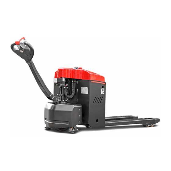
- Page 1 Mini Range ELECTRIC PALLET TRUCK CBD20-AMC1 OPERATION AND MAINTENANCE MANUAL Original Instruction HANGCHA GROUP CO., LTD. 3/2018...
- Page 2 FOREWORD Thank you very much for purchasing the A series mini range electric pallet truck of Hangcha Group . A series mini range electric pallet truck is a newly developed product for warehouse logistic, it owns characteristics as advanced performance, comfort operation, safety and security, low maintenance cost, and is an ideal tool for handling goods in warehouse, supermarket and workshop.
-
Page 3: Table Of Contents
Contents Part Operation and Maintenance ..................1 Notice for use .......................... 1 1.1 General ............................ 1 1.2 Use as required........................1 1.3 Approved application conditions ....................2 1.4 Cautions for the use of cold storage truck ................3 1.5 Proprietor responsibilities ......................3 1.6 Attachment installation or modification to the truck .............. - Page 4 8.2 Start running after deposit for a long time ................35 Maintenance .......................... 36 9.1 Maintenance general ......................36 9.2 Periodic maintenance schedule ..................... 37 9.3 Remove or installing the hood ....................39 9.4 Remove or installing the drive wheel cover ................40 9.5 Truck used oil and lubrication ....................
-
Page 5: Part Operation And Maintenance
Part Operation and Maintenance Notice for use 1.1 General Truck in this manual is only for lifting and transporting loads. It must be used, operated and maintained according to the information in this manual. Any other uses are outside the design envelope and can lead to injury to persons or damage to equipment and property. -
Page 6: Approved Application Conditions
1.3 Approved application conditions Used in specified area as factory, tourist attraction and recreation place. Operation only on secure, level surfaces with sufficient capacity. Operation only on routes that are visible and approved by the proprietor. Use in specified rated load. Average environment temperature under continuous operating condition +25 . -
Page 7: Cautions For The Use Of Cold Storage Truck
1.4 Cautions for the use of cold storage truck Use special oil for cold storage, maintain and replace periodically. All cold storage trucks cannot be shut down or parked in cold storage, or it may cause damage of hydraulic system and electric system. Before entering the cold storage, do necessary hydraulic and traction motion to the cold-storage truck, and then enter the cold storage after temperature rises. -
Page 8: Attachment Installation Or Modification To The Truck
1.6 Attachment installation or modification to the truck Without authorization by the manufacturer, it is not allowed to modify the truck privately. The mounting or installation of any attachments which will interfere with, or supplement, the functions of the truck is permitted only after written approval by the manufacturer has been obtained. -
Page 9: Truck Introduction
A series mini range electric pallet truck described in this manual should work under low working strength and its continuous working time should not surpass one hour. Users can get relevant information as rated load from the product model. CBD20-AMC1 Meaning Electric pallet truck Rated load capacity×100kg... -
Page 10: Functional Description
2.2 Functional description Frame – Beautiful and compact outline, concise and fluent line. – Adopted steel stamping and injection moulding process is sturdy and durable. Driving system – Drive unit adopts wheel type, with compact and simple structure. – Permanent-magnetic drive motor owns excellent performance. –... - Page 11 insures the safe operation. Anti-slope on gradient can keep the safety. The emergency button on the tiller head can effectively avoid the harm to the driver. The standard equipped electronic lifting limitation protect the pump motor from damaging dramatically and more energy saving. Maintenance Built-in charger and maintenance free gel battery, you don’t need to worry about them.
-
Page 12: Main Part Introduction
2.3 Main part introduction Item Description Item Description Control handle Load wheel Control lever Fork Lift cylinder Wire fixator Drive wheel cover Battery charging plug built-in plug Caster wheel Display (battery charge level indicator) Drive wheel Hood Fault indicator Emergency stop switch Key switch Charging light indicator (with built-in charger) Side door (built-in battery) -
Page 13: Display And Control
2.4 Display and control... - Page 14 Item Designation Function Control lever Control the steering and brake of the truck. Normally on normal condition. Failure regularity, see Fault indicator the failure code. It displays charger running state. Red light flashes-it is charging. Charging light indicator Yellow light is on- charging fault. Green light is on- charging finishes.
-
Page 15: Display (Battery Charge Level Indicator)
2.4.1 Display (battery charge level indicator) Display the Battery charge level indicator and the truck total work hour indicator Battery charge level indicator The multi-color ten-segment LED light bar is used to display the battery power status (5 green, 3 yellow, and 2 red LED light bars in sequence). -
Page 16: Standard Technical Data
2.5 Standard technical data The following technical data are all standard data. Our company reserves the right of alteration and extension. Model CBD20-AMC1 Operator type Pedestrian Load capacity Q (kg) 2000 Load center c(mm) Load distance, centre of drive axle to fork... -
Page 17: Product Plates And Warning Labels Location
2.6 Product plates and warning labels location Plates and labels, such as nameplate, load curve plate, warning labels must be legible, if identification is unclear, and must be replaced. The figure below shows the approximate location of the various identity resides. Before operating the truck, please understand the meaning of the various identities. - Page 18 Item Description Nameplate: The rated capacity on the nameplate is the max. load capacity by the label listed equipment. Any change to the forklift or other equipment may change rated capacity. Fault indicator Charging light indicator. Overnight charging recommend after use ! Manufacturer’s logo Hoist label: Strap points for crane lifting.
-
Page 19: Safety Instructions
accident. Safety Instructions – Make sure change the “safety parts” Only trained and authorized operator during the schedule maintenance. shall be permitted to operate the truck. – Wipe off the oil, grease or water on the soleplate, foot pedal and control lever. –... - Page 20 going up and down the slope, please you are easily to fall. Meanwhile, organize staff to repair. possibility of turnover will increase. Internal battery may generate explosive 14) Avoid sudden drive, stop or turn. gas, it’s prohibited any flame close the 15) Do not drive the truck when the forks in battery.
- Page 21 chassis and lifting component, once equipped with fire extinguisher. Driver clipped, it is dangerous to your life. It’s and manger should be familiar with the forbidden to put the head, hand, foot or fire extinguisher position and application body into the space between fork and method.
-
Page 22: Transport
Transport The forklift truck is designed for short-distance lifting,lowering and transporting load units, not suitable for long-distance travel. If needed, the forklift truck must be transported by using lifting device or platform to place on truck or trailer. 4.1 Lifting by crane WARNING Only use lifting gear with sufficient capacity (for truck weight see truck nameplate ). -
Page 23: Securing The Truck During Transport
4.2 Securing the truck during transport Correctly fix the forklift truck to avoid move when using truck or trailer. Procedure: – Park the truck securely. – Sling the tensioning belt around the truck and attach it to the fastening rings of the transporting vehicle. -
Page 24: Transport
4.3 Transport The pallet truck is designed for short-distance material handling only and is inappropriate for long-distance transportation. If needed, the truck must be transported by using lifting device or platform to place it on truck or trailer. Before operation, fix the pallet truck firmly on the transport vehicle with belt, and block the wheel to avoid relative motion during transportation. -
Page 25: Battery
Battery The truck equips with four 12V/50Ah maintenance-free colloidal batteries. When the battery temperature reaches 25 30 , its service life is the longest. Lower temperature reduces battery available capacity and higher temperature shortens battery service life. Per battery weighs about 20kg. 5.1 Safe operation rules for battery use –... - Page 26 capacity, or else it would shorten the endurance of the truck and the service life of the battery as well. – The matching between batteries and the chargers: matching on the charging parameter of the battery plays a significant role on the battery performance and its service life. Users should choose the qualified charger with same charging parameter as previous one when replacing the chargers.
-
Page 27: Battery Charging
5.3 Battery charging That is, during truck operation the battery discharge process, the battery over-discharge is prohibited. After the truck is running, it is timely to charge the battery. WARNING The truck comes with charger, the charger charging power supply must be single-phase power frequency AC power. -
Page 28: Additional Charge
5.3.3 Additional charge Charger structure enables to continue charging the partially charged battery in use. -
Page 29: Replacing Battery
5.4 Replacing battery Procedure: – Park the truck securely. – Remove the screws (36), and then remove the side door (9). – Remove the battery plug (37) from the truck socket (38). – Remove the battery positive and negative electrode. –... -
Page 30: New Truck Breaking-In
New truck breaking-in We recommended operating the truck under light load conditions for the first stage of operation to get the most from it. Especially the requirements given below should be observed while the truck is in a stage of 100 hours of operation –... -
Page 31: Operation
the scales. Add oil when insufficient. Operation 7.1 Check before operation In order for the safety truck operation and keep the truck in good condition, before starting the truck, you must check it carefully. Oil leak and liquid leak check Park the truck and check oil leakage. - Page 32 press the accelerator button to the outside of the body with thumb, and inspect the forward running condition; gradually press accelerator button to the inside of the body with thumb, and inspect the reverse running condition. 10) Brake system When the truck run forward or backward, push the handle to vertical position or press to level position to check the brake condition.
-
Page 33: Start Up
7.2 Start up Procedure: – Carry out check before operation and make sure each function and state is normal. – Pull up the emergency stop switch (16). – Plug the key into key switch (17), turn to “ON” position in clockwise. The instrument displays battery capacity. -
Page 34: Travelling
7.3 Travelling Driver should walk in front of the truck and keep at the side front of the truck when travelling. One hand holds the handle, and operates travel switch with thumb. Always watch moving direction and guide the truck. Or hold the handle with both hands and push the truck go forward. CAUTION Operator must wear protective boots. -
Page 35: Braking
Slow down Slowly loosen the thumb, the direction speed control button will return automatically and the truck slows down. Rear Rear Forward Forward 7.4 Braking When the thumb off the direction speed control button, pull the handle to braking range (B1 or B2) position or vertical position, the truck brakes. -
Page 36: Loading
– Drop the fork to the lowest position. – Turn off the switch to “OFF” position, press down the emergency disconnect switch, pull out the battery plug, and take off the key. – Fold up 7.7 Loading Procedure: – Drive the truck carefully up to the loads. –... - Page 37 – Travel backward and make the fork out of the load. – Drop down the forks to proper position.
-
Page 38: Park The Truck Securely
7.9 Park the truck securely Procedure: – Drive the truck to safe area or appointed area. – Fully lower the forks. – Turn off the key switch (17), and remove the key. – Press the emergency stop switch (16). -
Page 39: Deposit The Truck For Long Time
Deposit the truck for long time 8.1 Deposit for long time – Fully check the truck, especially check the wheel damage. – Check fluid oil for leakage. – Apply lubrication grease. – Check the joint face of cylinder piston rod for looseness, and if scratch on the piston rod surface. -
Page 40: Maintenance
Inspection and maintenance are usually ignored, you’d better find out the problems early and solve it in time. – Use authentic parts of Hangcha Group. – Don’t use different oil when changing or adding oil. Don’t rave about oil and electrolyte used at will, and carry on handling according to the local environmental protection laws and regulations. -
Page 41: Periodic Maintenance Schedule
9.2 Periodic maintenance schedule The service intervals stated are based on single shift operation under normal operating conditions. They must be reduced accordingly if the truck is to be used in conditions of extreme dust, temperature fluctuations or multiple shifts. The following servicing checklist indicates the operations to be performed and the respective intervals to be observed. - Page 42 Steering Test electric steering and its components. Check tiller recuperating function. Bearing lubrication Electrical system Test warning and safety devices in accordance with operating instructions Test the displays and controls. Check the function of micro switch and sensor. Test cable and motor attachments. Check contactors and/ or relays.
-
Page 43: Remove Or Installing The Hood
9.3 Remove or installing the hood Remove the hood Procedure: – Park the truck securely. – Unscrew the hood screws (41). – Lift the hood (15). – The wire fixate (12) and the battery charging plug (13) from the hood (15) to take off on. The hood is removed. -
Page 44: Remove Or Installing The Drive Wheel Cover
9.4 Remove or installing the drive wheel cover Remove the drive wheel cover Procedure: – Unscrew the drive wheel cover (4) of the four screws (40), remove the drive wheel cover. The drive wheel cover is removed. Installation and removal process is reversed. WARNING Remove or installing the drive wheel cover, carefully clip hand! -
Page 45: Truck Used Oil And Lubrication
9.5 Truck used oil and lubrication Filler plug for hydraulic oil Gliding surfaces Code Designation Mark, code Remark Normally L-HM32 Hydraulic oil Hydraulic system High and cold environment L-HV32 Grease Automobile general 3 # lithium base lubricant Nozzle and lubrication CAUTION Into the fuel tank of hydraulic oil must be filtered, and the injection volume of the hydraulic oil tank does not exceed the maximum scale. -
Page 46: Check The Fuses
9.6 Check the fuses Procedure: Maintenance work to complete preparations before the operation. Remove the hood. Check the fuse (42,43) values are correct, if necessary, replace. Designation Control circuit Specification Fuse Pump motor Fuse Controller... -
Page 47: Replace Wheels
driving wheels from the drive unit. 9.7 Replace wheels Procedure: – Dismantle the drive unit from the truck. CAUTION Strike the edge of the driving wheels – Remove the 12 socket hexagon screws evenly and symmetrically. which is used to fix the driving wheels Do not scratch the outer surface of with a S=5mm hex wrench. -
Page 48: Relevant Safety Directive Or Standard (Ce)
Relevant safety directive or standard (CE) After CE certificated, the truck meets the following directive and standard: – 2006/42/EC machinery directive namely Directive of the council of the laws of the member states concerning machinery , 2000/14/EC Noise Directive Namely Directive of the council of the laws of the member states concerning noise radiation of outdoor equipment ;... -
Page 50: Part Structure, Principle And Maintenance
Part Structure, Principle and Maintenance Drive Unit 1.1 Data sheet Speed ratio of reduction gear box 24.6857 Max. wheel torque N•m Max. wheel load 1000 Rated voltage Rated power Rated current Rated speed r/min 3300 Drive motor Working system S2=45min Insulation grade Protection grade IP44... -
Page 51: Assemble And Use Notice
1.2 Assemble and use notice – When assemble, scrub the oil seal on the product. Avoid product damage, no disassemble at will. – Avoid each fitting surface and exposed gear impact, thus influence installation. – Normal working oil temperature is 70 . –... -
Page 52: Drive Motor
1.4 Drive Motor Wiring Diagram of Motor 24VDC Black 24VDC Black Motor use notice – Keep clean and dry around the motor, and do no place other objects on or in the motor. – Do not use with overload. – Never coexist with strong magnetic object. - Page 53 cloth, when there is grease on the surface, immerse the cloth in alcohol to wipe(park). – Check if all fasteners are tight. – Brush carrier should be fastening and no loose. If turn or remove the brush carrier needed, only mark can loosen the end cap bolt. Aim at marker line to tighten screw when brush carrier reset to keep the brush in neutral position.
- Page 54 – After polishing crocus cloth and cleaning commutator, motor should work under limited speed to ensure safety until the brush working surface polishes.
- Page 55 Fault diagnosis Probable cause Fault All copper sheet blacken Pressure of the brush is not right ·Short circuit of commutator segments Commutator segments blacken in ·Short circuit of armature coils group according to certain sequence ·The welding of commutator segments and armature coils is not good or short circuit.
-
Page 56: Electromagnetic Brake
1.5 Electromagnetic brake The spring-loaded electromagnetic brake is applied in the truck which is a single disk brake with double friction surfaces. By use of the pressure spring, powerful braking torque would be generated when power off. The brake could be released by the electromagnetic effect. 1.Mounting Bolt of the Brake 2.Stator Module 3.Brake Pad... -
Page 57: Electromagnetic Brake Working Principle
1.5.1 Electromagnetic brake working principle Motor shaft (9) is connected with shaft sleeve (4) by passing through the flat key. And shaft sleeve (4) is connected with brake pad (3) by passing through the splines. When the stator (11) is block out, the force produced by the pressure spring (10) would act on the armature (8) which makes rotated the brake pad (3) driven by the motor shaft connected closely between the armature (8) and cover plate (5). -
Page 58: Electromagnetic Brake Installation
1.5.2 Electromagnetic brake installation – Put the flat key (13) into the key groove of the motor shaft (9). Press the shaft sleeve (4) to the motor shaft (9) and fasten it with the inner spring. – Install the friction disk (5) to the end face of the motor by using three mounting bolts of the friction bolts (12). -
Page 59: Maintenance
WARNING No broken wire sheath, or else the circuit might be damaged. Do not process the locating surface or the holes of the production without authorization, or else the magnet loop would be influenced. Do not over press when fitting the motor shaft. Make sure no damage on the friction surface and wipe off the burr of the mounting holes and surfaces. -
Page 60: Adjust The Air Gap Of The Brake
1.5.4 Adjust the Air Gap of the Brake Rated air gap Z grows with the friction. In order to there is sufficient braking torque, the air gap must be set before it reaches to the maximum value. The air gap can be adjusted by several times. When the thickness of brake pad becomes the minimum value(see the specification table below), the brake pad must be replaced. - Page 61 Under the general operating conditions, the first set of the air gap is usually after 1500 to 2000 hours service of the brake and it is suggested to adjust the air gap every 6 months. If it comes to a poor working condition, such as frequent use of brake and repeated emergency stops the air gap should be set when the brake the shorten the adjustment interval for the first time.
-
Page 62: Common Fault And Troubleshooting
1.5.5 Common fault and troubleshooting Fault Probable cause Corrective action Power is obstructed Connect Too low exciting voltage Check voltage and adjust. Brake does not Improper air gap Adjust air gap work Stator coil breaks Replace stator Oil dirt mixed in Clean oil dirt Install the switch to the DC circuit Switch installed to AC circuit... -
Page 63: Hydraulic System
Hydraulic system 2.1 Hydraulic system working principle... -
Page 64: Hydraulic System Fault Diagnosis And Correction
2.2 Hydraulic system fault diagnosis and correction Fault Probable cause Corrective action Low oil level Fill to the specified oil level No oil pumps Clean oil pipe and oil tank. If hydraulic oil is from the pump Blocking of strainer dirty, please change it. -
Page 65: Electric System
Electric system 3.1 Electrical schematic diagram... -
Page 66: Drive Motor Controller
3.2 Drive motor controller 3.2.1 Maintenance Controller has no user repair parts. Do not try to open, repair or alter the controller. Otherwise it may damage the controller and also invalid the guarantee. It’s suggested to keep the controller clean and dry, periodically check and get rid of diagnose historical files. -
Page 67: Diagnostics And Troubleshooting
3.2.2 Diagnostics and Troubleshooting When faults happen, try to restart by resetting the key switch after confirmed that faults are not caused by faulty wiring connection or mechanical failure. If the faults are still on, shut down the key, check for incorrect connection or corruption of the pin 35 connecter, reconnect after repaired and cleared, and then restart again. - Page 68 Troubleshooting Chart Led Codes Fault indicator status Fault Possible Cause no power or defective controller controller powered up; No faults 1 Temperature >8 C or < -10 . 2 Battery contact bad.. ¤ ¤ Thermal Fault 3 Work under extreme severe environment. 4 Electromagnetic brake does not release normally.
-
Page 69: Attachment Table For Bolt's Tightening Torque
Attachment Table for bolt’s tightening torque If not specified, select the tightening torque from the below table Unit N·m Grade Bolt’s diameter 9 12 10 12 12 15 14 18 22 29 20 25 25 31 29 39 44 58 35 44 44 54 49 64... - Page 70 Maintenance Record Date Repair, maintenance content Serviceman...
- Page 71 HANGCHA GROUP CO. , LTD. Address: 666 Xiangfu Road, Hangzhou, Zhejiang, China Fax: 0086-571-88926789 0086-571-88132890 ZIP:311305 Web: http://www.hcforklift.com E-mail: sales@hcforklift.com...
Need help?
Do you have a question about the CBD20-AMC1 and is the answer not in the manual?
Questions and answers
Busco como técnico de mantenimiento la contraseña de servicio para realizar cambio de contraseña
The service (administrator) password for the HANGCHA CBD20-AMC1 to change the password is 22222.
This answer is automatically generated