
Related Manuals for HANGCHA A Series


Summary of Contents for HANGCHA A Series
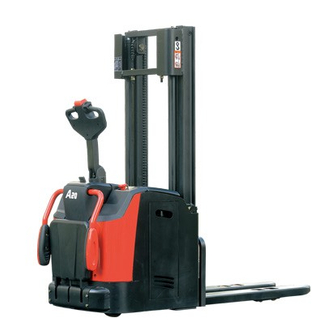
- Page 1 Series CDD12/14/16-AC1-L ELECTRIC STACKER CDD12/14/16-AC1S-L CDD12/14/16-AC1S-LI CDD12/14/16-AZ3S-L OPERATION AND MAINTENANCE MANUAL Original Instruction HANGCHA GROUP CO., LTD. 11/2020...
- Page 2 Part Ⅰ of this manual is about the brief introduction and correct operation of the A series high range stand-on electric stacker with initial lift, which will tell you how to operate safely and maintain preventively;...
-
Page 3: Table Of Contents
Contents Part Ⅰ: Operation and maintenance ................... 1 Correct Use and Application ....................1 1.1 General ............................ 1 1.2 Correct application ........................1 1.3 Approved application conditions ....................2 1.4 Cautions for the use of cold storage truck ................3 1.5 Cautions for the use of lithium battery truck ................ - Page 4 Relevant safety directive or standard (CE ) ................69 Part Ⅱ: Structure, Principle and Maintenance ................. 71 Drive system.......................... 71 1.1 Reduction box ........................72 1.1.1 Working principle ........................73 1.1.2 Dismount and assemble order ....................74 1.1.3 Notice to installment and use ....................74 1.1.4 Fault and troubleshooting ......................
-
Page 5: Part Ⅰ: Operation And Maintenance
Part Ⅰ: Operation and maintenance Correct Use and Application 1.1 General The industrial truck described in the present operating instructions is designed for lifting, lowering and transporting load units. It must be used, operated and serviced in accordance with the present instructions. Any other type of use is beyond the scope of application and can result in damage to personnel, the industrial truck or property. -
Page 6: Approved Application Conditions
1.3 Approved application conditions - Used in specified area as factory, tourist attraction and recreation place. - Operation only on secure, level surfaces with sufficient capacity. - Operation only on routes that are visible and approved by the proprietor. - Use in specified rated load. -... -
Page 7: Cautions For The Use Of Cold Storage Truck
1.4 Cautions for the use of cold storage truck - Use special oil for cold storage, maintain and replace periodically. - All cold storage trucks cannot be shut down or parked in cold storage, or it may cause damage of hydraulic system and electric system. -... -
Page 8: Cautions For The Use Of Lithium Battery Truck
1.5 Cautions for the use of lithium battery truck - Never charge below 0℃; - If the lithium battery needs to interrupt or suspend charging, do not hot plug, avoid current arc to damage charging base; - Charge the lithium battery immediately after per discharge to avoid battery loss; -... -
Page 9: Proprietor Responsibilities
1.6 Proprietor responsibilities For the purposes of the present operating instructions the “proprietor” is defined as any natural or legal person who either uses the industrial truck himself, or on whose behalf it is used. In special cases (e.g. leasing or renting) the proprietor is considered the person who, in accordance with existing contractual agreements between the owner and user of the industrial truck, is charged with operational duties. -
Page 10: Truck Introduction
Truck introduction 2.1 Application This manual introduces the industrial truck is a four-wheel, tiller-operated electric stacker with a folding operator platform, safety side arms and a steered drive wheel. The industrial truck is designed for lifting and transporting goods on level floors. Wheel arm lift increases the ground clearance when transporting goods on uneven surfaces. -
Page 11: Main Parts And Functional Description
2.2 Main parts and Functional Description 2.2.1 Main part introduction Item Component Item Component Tiller Emergency Disconnect switch Key switch Meter Lock switch Battery panel Load wheels Safety side arms Drive wheel Wheel arm Folding operator platform Forks Rear panel assy Mast Castor wheel Mast shield... -
Page 12: Functional Description
2.2.2 Functional Description Safety Mechanisms - Pressing the Emergency Disconnect switch rapidly cuts out all electrical functions in hazardous situations. - Traveling speed will be automatically reduced after fork lifting 500mm. - Automatic speed reduction for cornering. Curve Control limits the speed and acceleration when cornering. - Page 13 and lowering. - When lifting is activated, the pump unit starts to operate, supplying hydraulic oil from the oil reservoir to the lift cylinder. Electric system - 24 volt system. - The latest AC control system realizes accurate and stable control, and higher efficiency. -...
-
Page 14: Displays And Controls
2.3 Displays and Controls 19 20... - Page 15 Item Control/Display Symbol Function Control the truck steer and brake. Set to brake zone (B): The truck brakes mechanically. Tiller Set to travel zone (F): The mechanical brake is released and the truck is ready for operation. Display battery charging status, running hours and fault Display information.
- Page 16 Item Control/Display Symbol Function Wheel arm lower button Lowers the wheel arms at a constant speed. Low speed indicator When the indicator light is always on, it means the truck light is in low speed mode.
-
Page 17: Display
identified Operator Service 2.3.1 Display Technician thereby finding the fastest solution to the problem. Hourglass Symbol: It is normally off; it blinks when the Hour Meter is working. Hour meter An alpha-numeric liquid crystal display is ALARM LED LCD DISPLAY fitted in the centre of the unit that shows the LED function Hours Worked. - Page 18 display screen alphanumeric characters, dot-matrix LCD liquid crystal display, can display vehicles fault code, battery soc and total running time. Vehicles when the normal operation of the display shows the battery remaining power. Service indicator(red LED) When the controller to detect fault information, Battery State of charge the red LED indicator light flashing, at the same time LCD display shows two digits of the...
- Page 19 D13L Display characteristics: Wide voltage input range: 9V~60V; Built-in anti-reverse circuit; Beautiful appearance and unique alarm indication design; Implement time-limited vehicle speed, power, hour meter, and fault; Positive IP65 protection level, able to adapt variety complex environments;...
-
Page 20: Open Or Down The Safety Side Arms
display; 2.3.2 Open or down the safety side arms When the battery level is lower than 20%, Open the safety side arms: the battery icon flashes; Push the lock switch (3) with one hand and the When the hour meter is in the main other hand lift the safety side arms (4) until it rotates to certain angle, releases the lock switch interface, it is always displayed;... -
Page 21: Standard Technical Specifications
2.4 Standard technical specifications The following technical specifications are all standard data. Technical modifications and additions reserved. Model CDD12-AC1-L CDD14-AC1-L CDD16-AC1-L Operator type Standing Standing Standing Load capacity Q (kg) 1200 1400 1600 Load center distance C(mm) Load distance, centre of drive axle to fork (lift/descent) x(mm) 683/748 683/748... - Page 22 CDD12-AC1S-L CDD14-AC1S-L CDD16-AC1S-L Model CDD12-AZ3S-L CDD14-AZ3S-L CDD16-AZ3S-L Operator type Standing Standing Standing Load capacity Q (kg) 1200 1400 1600 Load center distance C(mm) Load distance, centre of drive axle to fork x(mm) Wheelbase y(mm) 1507 1507 1507 Service weight with battery 1295 1300 1350...
- Page 23 Model CDD12-AC1S-LI CDD14-AC1S-LI CDD16-AC1S-LI Operator type Standing Standing Standing Load capacity Q (kg) 1200 1400 1600 Load center distance C(mm) Load distance, centre of drive axle to fork x(mm) Wheelbase y(mm) 1507 1507 1507 Service weight with battery 1295 1300 1350 Weight Tyres type...
- Page 24 65.3...
- Page 25 Mast Specification: 1.2t/1.4t/1.6t Fork lift Max. fork Mast Mast Load capacity at 600mm Free lift Type height height lowered extended height (h3+h13) 1.2t 1.4t 1.6t 2000 2090 1582 2582 1200 1400 1600 2500 2590 1832 3082 1200 1400 1600 2700 2790 1932 3282...
-
Page 26: Product Plates And Warning Labels Location
2.5 Product plates and warning labels location Plates and labels such as nameplate, load charts, warnings and strap points must be legible at all times. Replace if necessary. The figure below shows the approximate location of the various identity resides. Before operating the truck, please understand the meaning of the various identities. - Page 27 Any change to the forklift or other equipment may change rated capacity. Series tonnage label: A series, rated capacity is X×100kg Add hydraulic oil decal. Warning label: it is forbidden that the operator`s foot is not on the platform during operation.
-
Page 28: Nameplate
2.5.1 Nameplate Item Description Item Description Model-type Rated capacity (kg) Serial No. Weight without battery (kg) Load center (mm) Max. allowbabl battery weight (kg) Battery voltage (V) Min. allowable battery weight (kg) Rated drive power (kW) Year of manufacture Max. lifting height (mm) Note: For queries regarding the truck or ordering spare parts always quote the truck serial number (39). -
Page 29: Truck Rated Capacities And Load Centers Graph
2.5.2 Truck rated capacities and load centers graph The rated capacities and load centers graph draws the load center position and the rated load weight change curve when the lift height of the truck is given. RATED CAPACITIES AND LOAD CENTRES GRAPH RATED CAPACITIES AND LOAD CENTRES GRAPH RATED CAPACITIES AND LOAD CENTRES GRAPH SUBTRACT 700kg WITH SIDESHIFTER... -
Page 30: Safety Rules
– No smoking or any spark, smoke near the Safety Rules battery when checking. Only trained and authorized operator shall – Be careful of scald when checking motor be permitted to operate the forklift. and controller. The controller equips with energy accumulator, do not touch between B+ and B- to avoid electric injury. - Page 31 battery. Never allow the tools close two 18) Cause the wheels of pallet truck is small, poles of the battery to avoid spark or short it is not allowed to run on the street, and circuit. only for driving in specified stacking place. 19) It’s forbidden to put the head, hand, foot or body under the forks.
- Page 32 air relative humidity: less than 90% (20℃) . lighting. 31) Jump out from the pedal far-away from Altitude should not exceed 2000m. the truck, When a stand-on end-control 23) After power off, brake works and the . . . . . . . . . . . . . . . . . . .. . . . .. . . . . . truck to step off and away from the truck in truck can not be towed(dragged) ....
-
Page 33: Transport
Transport The forklift truck is designed for short-distance lifting, lowering and transporting load units, not suitable for long-distance travel. If needed, the forklift truck must be transported by using lifting device or platform to place on truck or trailer. 4.1 Lifting the truck by crane Procedure: –... -
Page 34: Securing The Truck For Transport
4.2 Securing the truck for transport Correctly fix the forklift truck to avoid move when using truck or trailer. Procedure: – Move the truck onto the transporting truck. – Park the truck securely. – Strap the belts (51) around the truck and tension them sufficiently. Using the wedge fixed wheels when necessary. -
Page 35: Transport
4.3 Transport The forklift truck is designed for material handling only and is inappropriate for long-distance transportation. If needed, the forklift truck must be transported by ship, train or lorry, block tires with solid chocks, and bind body firmly. – Place the truck on the long-distance transportation tool through loading platform or hoisting device. -
Page 36: Battery
– Inspect electrolyte level every week. Battery When electrolyte level is low, you must 5.1.1 Attention for using add distilled water to the level appointed. battery WARNING No firing The shortage of the electrolyte will Explosive gas can be produced in the internal cause storage battery... - Page 37 Do not open the lithium battery cover maintenance, lithium battery failure, timely contact with the manufacturer. The battery is not used at a loss of power. To ensure the battery life, should avoid the discharge depth of more than 80% of Measures in summer the rated capacity of the battery.
- Page 38 reverse charge can cause the battery department to obtain the correct technical voltage to zero, scrapped in advance. support. 12) If the battery smells, heat, discoloration, 18) Prohibit the use of this series of products deformation or use, storage, charging any by children and other people who lack anomalies, battery...
- Page 39 fire extinguisher. inadvertent contact, take off contaminated 25) Evacuate persons in the danger area if clothing and wash the infection with plenty the battery is cracked or ignited, and of water and soap for at least 15 minutes, immediately spray with water or soak a do not rub the ointment.
-
Page 40: Dimension / Weight
5.2 Dimension / Weight Item 1.2t-1.4t 1.6t Length (L) Width (W) Height (H) Min. allowable battery weight Max. allowbabl battery weight WARNING Battery weight and dimensions have considerable influence on operational safety of the truck. When installing or replacing battery, be sure that battery in the fixed position. -
Page 41: Charging The Battery
5.3 Charging the battery Procedure: - Drive the truck to appointed charging place, park the truck and render if safe. - Open the battery panel (11). - Remove the battery plug (53) from the truck socket (52). - Open the filler cap of each battery monomer. -... - Page 42 Daily charging ·The storage battery that has been made first charging and used in normal condition, then charged again, it is named daily charging. ·Its way is almost same as the first charging. ·The recharging volume is 1.2 times than the last electric discharging. But the new storage battery’s former five times’...
- Page 43 WARNING If the level of the electrolyte is low, using the storage battery will cause the storage battery over-heat and shorten the storage battery’s service life. 1. Inspect electrolyte The storage battery without a dobber It is proper to pour the electrolyte 15-20mm above the electrode plate. The storage battery with a dobber According to the dobber of the ventilation cover, read the level position of the electrolyte.
- Page 44 The storage battery without a dobber When the electrolyte is above 15-20mm of the electrode plate, stop replenishing ④ After replenishing the distilled water, close the ventilation cover and box cap. ⑤ Use the damp cloth to clean the surface of storage battery cells. WARNING ...
- Page 45 ③ Numerate the reading of the densimeter. CAUTION The dobber of densimeter must rise uprightly without depending on the glass pipe. 2) Measuring the proportion Use gravimeter to calculate the electrolyte proportion. 3) Conversion of the specific gravity The specific gravity at the standard temperature of 30 C should be converted as follow: + 0.0007( t - 30 ) Therein to:D30 ——the specific gravity at the standard temperature of 30...
- Page 46 : Charger Storage battery of this truck equips with PCA Automatic Charger Operation Instruction. 1. The charger is automatic high frequency charger. The capacity voltage is 220V AC. The input current is not less than 15A. The output voltage is DC 36V. Maximum charge current is 35A.
- Page 47 in the water, as this may cause electric shock and cause personal injury. Provide adequate ventilation during charging. To avoid damage to charger cord plug and receptacle, do not pull on charger cord plug. Do not twist, rock or bend plug sideways. Do not use if plug or receptacle is damaged.
- Page 48 Charging steps Park the vehicle safely in the designated charging area as required, close the switch and unplug the key. – Insert the charger power plug into a suitable power outlet. – Start the charging process. – Turn on the charger power switch. Unplug the charging plug after charging is complete, turn off the charger power switch, and unplug the charger plug.
-
Page 49: Changing The Battery
5.4 Changing the battery Procedure: – Park the truck securely. – Open the battery panel (11). – Disconnect the battery connector (53) from the truck connector (52). Place the battery cable on the tray so that it cannot be severed when the battery is pulled out. -
Page 50: New Truck Breaking-In
New truck breaking-in We recommended operating the truck under light load conditions for the first stage of operation to get the most from it. Especially the requirements given below should be observed while the truck is in a stage of 100 hours of operation: -... -
Page 51: Operation
Operation 7.1 Check before operation In order for the safety truck operation and keep the truck in good condition, before starting the truck, you must check it carefully. Oil leak and liquid leak check Park the truck, and check the truck for Close the hood, and open the battery cover hydraulic oil, gear oil or electrolyte leak. - Page 52 condition. 10) Brake system When the truck run forward or backward, push the handle to vertical position or press to level position to check the brake condition. 11) Steering system Left or right turn the handle to make the truck run around 3 turns, and then check if the steering system is normal.
-
Page 53: Starting Up
7.2 Starting up Procedures: - Fold out the safety arms (4) and folding platform (6). - Step on the folding platform (6). - Pull the Emergency Disconnect (9) to unlock it. - Insert the key in the key switch (10) and turn it as far right as it will go. The truck is operational. -
Page 54: Travel
7.3 Travel WARNING No turn, inclines when going uphill and downhill. Never park on the slope. Slow down when going downhill and ready for braking. Travel according to regulated route. The road should keep clean, no slipping The truck has two travel modes: -... -
Page 55: Steering
7.4 Steering ESP(electric steering power) system is easier to operate due to less activation force required. Procedure: - Move the tiller (1) to the left or right. The truck is steered in the required direction. -
Page 56: Brakes
7.5 Brakes The brake pattern of the truck depends largely on the travel route conditions. The driver must take this into account when travelling. The truck can brake in different ways: - By inversion braking (controller) - By regenerative braking (coasting) -... -
Page 57: Lifting Load
7.6 Lifting load Lift one pallet Procedure: - Drive the truck carefully up to the pallet. - Slowly insert the forks into the pallet until the fork shank touches the pallet. The load unit must not extend by more than 50mm beyond the fork tips. -... -
Page 58: Transporting Load
7.7 Transporting load Procedure: - Load unit positioned correctly on the forks. - Mast lowered for transport (approx. 150mm-500mm above the ground). - Accelerate and decelerate gradually. - Adapt your travel speed to the conditions of the route and the load you are transporting. -... -
Page 59: Depositing Load
7.8 Depositing load Depositing when transport one pallet Procedure: - Drive carefully up to the storage location. - Press the “Lower load handler” button (22). Avoid depositing the load to avoid damaging the load and the load handler. - Carefully lower the load handler so that the forks are clear of the load. -... -
Page 60: Parking The Truck Securely
7.9 Parking the truck securely Procedure: - Drive the truck to safe area or appointed area. - Fully lower the load handler and wheel arms. - Set the control handle to the " Straight position". - Switch off the truck (12) and remove the key. -... -
Page 61: Deposit The Truck
Deposit the truck 8.1 Deposit the truck for long time - Fully check the truck, especially check the wheel damage. - Check fluid oil and electrolyte for leakage. - Apply lubrication grease. - Check the joint face of cylinder piston rod for looseness, and if scratch on the piston rod surface. -
Page 62: Maintenance
Inspection and maintenance are usually ignored, you’d better find the problems early and solve it in time. – Use authentic parts of Hangcha Group. – Don’t use different oil when changing or adding oil. Don’t rave about oil and electrolyte used at will, and carry on handling according to the local environmental protection laws and regulations. -
Page 63: Periodic Maintenance Schedule
9.2 Periodic maintenance schedule The service intervals stated are based on single shift operation under normal operating conditions. They must be reduced accordingly if the truck is to be used in conditions of extreme dust, temperature fluctuations or multiple shifts. The following servicing checklist indicates the operations to be performed and the respective intervals to be observed. - Page 64 Motor ● Clean the foreign body on the motor ● Clean or replace the bearing ● Check the carbon brush and commutater for worn, whether spring is normal ● Whether the connection is correct and firm. ● Brush carbon powder on shift plate and shift device. Transmission ●...
- Page 65 Hydraulic system ● Test hydraulic system. Check that hydraulic ports, hose and pipe lines are secure, check for ● leaks and damage. Check cylinders and piston rods for damage and leaks, and make sure ● they are secure. ● Check hydraulic oil level and top up if necessary. ●...
-
Page 66: Truck Used Oil And Lubrication
9.3 Truck used oil and lubrication Filler plug for hydraulic oil Hydraulic oil drain plug. Gear oil add plug Gear oil drain plug Lubrication part Grease nipples Code Designation Mark, code Remark Normally:L- HM32 Hydraulic oil Hydraulic system High and cold environment:L- HV32 Gear oil GL-5 85W/90 Reduction box... - Page 67 Change the gear oil – Park the truck at level ground. – Wipe off oil add and drain plug. – Unscrew oil add plug (65). – Place an appropriate container under oil drain plug (66), unscrew oil drain plug (66), and drain the oil to the container.
- Page 68 Change hydraulic oil – Park the truck at level ground. – Wipe off oil add and drain plug. – Unscrew oil add plug (67). – Place an appropriate container under oil drain plug (68), unscrew oil drain plug (68), and drain the oil to the container. –...
-
Page 69: Replace The Key Safe Parts Periodically
9.4 Replace the key safe parts periodically Users should replace the parts periodically according to the following table. If the part is abnormal before the replacing time, it should be replaced immediately. Key safe part’s description Term of using (year) Hydraulic hose for lifting system 1~2 High-pressure hose, hose for hydraulic system... -
Page 70: Removing The Rear Panel Assy
9.6 Removing the rear panel assy Procedure: – Park the truck securely. – Fold out the safety arms and folding platform. – Undo the four groups of bolts (58) on the rear panel assy (7) with a wrench. – Lift the rear panel assy (7), remove it from the truck and place it securely next to the truck. The panel is now disassembled. -
Page 71: Removing The Safety Guard
9.7 Removing the safety guard Procedure: – Park the truck securely. – Undo the six groups of screws (59) on the safety guard (16) with a wrench. – Lift the safety guard (16), remove it from the mast and place it securely next to the truck. The satety guard (16) is now disassembled. -
Page 72: Install The Load Bracket
9.8 Install the load bracket This truck does not equip with load backrest as standard, but leaves four threaded holes for installment. If load bracket (59) is needed, tighten with four combined bolts (58). Warning Be careful when installing the load bracket. -
Page 73: Relevant Safety Directive Or Standard (Ce )
Relevant safety directive or standard (CE ) After CE certificated, the truck meets the following directive and standard: – 2006/42/EC machinery directive (namely Directive of the council of the laws of the member states concerning machinery), 2000/14/EC Noise Directive (Namely Directive of the council of the laws of the member states concerning noise radiation of outdoor equipment);... -
Page 75: Part Ⅱ: Structure, Principle And Maintenance
Part Ⅱ: Structure, Principle and Maintenance Drive system Drive system is vertically arranged and rigid coupled with the frame. Drive system is mainly consisted of drive seat, reduction box, drive wheel, drive motor and electromagnetic brake etc. 1. Electromagnetic brake 2. -
Page 76: Reduction Box
1.1 Reduction box The truck used reduction box, light and controllable vehicle driving device, which adopts two grades reduce speed gear, namely grade-one cylindrical gear and grade-two spiral bevel gear. This reduction gear box owns traits like small size, light weight, large transmission ratio, small radius of gyration, high efficient and simple structure, which enables turn on site and equip with motor vertically that cause the radius of gyration on the carriage is small. -
Page 77: Working Principle
1.1.1 Working principle Simple figure of reduction box is as Fig.2-3, motor driving gear 1 drives driven gear 2, driven gear 2 drives driving spiral bevel gear 3 to transfer to driven spiral bevel gear 4, then the driven spiral bevel gear 4 drives the output of output flange 5. -
Page 78: Dismount And Assemble Order
1.1.2 Dismount and assemble order Dismount and disassemble the reduction box according to the following order: - Dismantle driving wheel (wheels); - Open oil discharging bolt and discharge the oil; - Disassemble swing bearing and top shell articles; - Disassemble driven cylindrical gear; -... -
Page 79: Motor
1.2 Motor Traction motor Traction motor is three phase AC motor, maintenance-free, but needs periodical check and clean. When tighten the upper nut on the wiring board, lock the lower nut to avoid looseness, and the suggested tightening torque is T=10.2Nm~12.4Nm. Rated Rated Rated... - Page 80 Steering motor DC steering motor is permanent magnet brush motor with planetary reduction box. ①Output shaft ②Output shaft bearing ③Annular gear ④Second stage planet gear ⑤Split type planet carrier ⑥First stage planet gear ⑦Motor shaft ⑧Motor shaft bearing ⑨Motor housing ⑩Motor stator ⑪Motor rotor ⑫Motor rear cover...
- Page 81 Motor use notice - Parts of stator have been adjusted; users mustn’t unpack and adjust randomly. - Keep clean and dry around the motor, place no other material on its inner or outer. - Wipe off the sand and other adhesion on the housing in order not to affect heat dissipation. -...
- Page 82 AC Motor fault diagnosis Fault Probable cause Power is not on(at least two phase off) After power is on, the motor does not Fuse fusing(at least two phase fusing) rotate, but without noise, odor or Overcurrent relay adjusts too small smoke.
- Page 83 Fault Probable cause Reduce too much number of stator windings when repair motor winding. Power voltage too high. Y connected motor wrongly connect to Δ Motor without load, current During motor assemble, rotor oppositely connects, balance, but the value is large make stator core unaligned, effective length shortens.
- Page 84 Fault Probable cause over large current heats the winding. When remove winding for overhaul, use improper way that burn the iron core. Rotor and stator core rub. Motor overloads or start up frequently. Cage rotor break. Motor overheating or smoking Motor lacks phase, two phases run.
- Page 85 DC Motor fault diagnosis Correctives Probable cause Fault Small brush contact surface Grind brush Over brush wear Replace new brush Oil stain on commutator surface Clean commutator surface Commutator decentration or commutator Process commutator outer circle segment extrusion Large spark Motor overload Motor overload Large mechanical vibration...
-
Page 86: Electromagnetic Brake
1.3 Electromagnetic brake The adopted brake of this truck is spring weighted electromagnetic brake. This brake is one-chip brake, owns two friction surfaces. It can generate strong brake torque through compressed spring in the state of power off, and electromagnetic induction realizes brake release. 1. -
Page 87: Working Principle
1.3.1 Working principle Shaft(9) connects shaft sleeve(4)through flat key; shaft sleeve(4) connects friction disk assembly(3) through spline. When the stator (11) is off power, spring (10) generated force works on the armature(8), friction disk assembly(3) that drives the shaft(9) to rotate, grips between armature(8) and friction disk(5), thus generates braking torque. -
Page 88: Brake Installment
1.3.2 Brake installment – Place flat key(12) to the key groove of motor shaft(9), press shaft sleeve(4) to the shaft(9), and fix with inner snap ring(13). – Place friction disc(5) on the end face of motor. – Cover friction brake disc(3) to the shaft sleeve. –... - Page 89 WARNING No damage on the outer of wire to avoid circuit damage. Never process the locating face and hold of the product to avoid magnetic return path. Mount on the motor shaft lightly, no damage the friction surface, get rid of burr from mounting hold and face, install shaft sleeve on the shaft, and fix with snap spring.
-
Page 90: Brake Air Gap Adjustment
1.3.3 Brake air gap adjustment Rated air gap ”Z” will be large for wear. Make sure the brake get enough brake torque, readjust air gap before the air gap reach the largest air gap value. Air gap can be adjusted repeatedly, when the thickness of friction braking plate reaches the allowable minimum thickness (refer to specification table), replace the friction disk assembly. -
Page 91: Maintenance
1.3.4 Maintenance - If work in high temperature environment for long time, please prevent rust, it may influence use if there is rust on the suction surface. - Do not touch the friction surface with hand, no oil stain, otherwise it cannot reach the maximum torque. -
Page 92: Common Fault And Troubleshooting
1.3.5 Common fault and troubleshooting Fault Probable cause Corrective action Power is obstructed Connect Too low exciting voltage Check voltage and adjust. Brake does not Improper air gap Adjust air gap work Stator coil breaks Replace stator Oil dirt mixed in Clean oil dirt Install the switch to the DC circuit Switch installed to AC circuit... -
Page 93: Hydraulic System
Hydraulic system Hydraulic system is mainly composed of hydraulic unit, lifting cylinder and rubber tube etc. 1. Hydraulic unit 2. Mounting bracket 3. Oil tube assembly 4. Oil tube assembly 5. Lifting cylinder 6. Oil tube assembly 7. Left lifting cylinder (mast lift) 8. -
Page 94: Hydraulic System Working Principle
2.1 Hydraulic system working principle... -
Page 95: Hydraulic Unit
2.2 Hydraulic unit The truck adopts combined hydraulic unit, and is composed of DC motor, relay, coupling, valve seat and valves (solenoid directional valve, safety valve, one-way valve, governor valve and oil blockage), gear pump, pipeline, oil filter and fuel tank etc. Notice -... -
Page 96: Hydraulic System Fault Diagnosis And Correction
2.3 Hydraulic system fault diagnosis and correction Fault Probable cause Corrective action Low oil level Fill to the specified oil level. No oil pumps from the pump Clean oil pipe and oil tank. If hydraulic oil is dirty, Blocking of strainer please change it. -
Page 97: Electric System
Electric system Electric system of this truck is double wire system, all circuits do not ground. Working voltage is DC24V. 3.1 Principles of electrical system CDD12/14/16-AC1S-L and CDD12/14/16-AC1S-LI... - Page 98 CDD12/14/16-AZ3S-L...
-
Page 99: Fault Code Table
3.2 Fault code tableC1 Programmer display Deep fault Code Probable fault reason reason/troubleshooting Fault display Controller Overcurrent 1. External short of phase U,V,W Reason:Phase current exceeds Motor stops working motor connections limited current Main connector disconnects 2. Motor parameters do not match. Troubleshooting:restart the key EM brake shutdown 3. - Page 100 Programmer display Deep fault Code Probable fault reason reason/troubleshooting Fault display Severe Overvoltage 1. Setup error of battery parameter. Reason:When MOSFEET axle Motor stops working 2. High battery impedance. working, capacitor voltage Main contactor disconnects Battery disconnects when exceeds the minimum voltage Electromagnetic brake disconnects regenerative breaking.
- Page 101 Programmer display Deep fault Code Probable fault reason reason/troubleshooting Fault display “set_digout()” by VCL, and restart. Motor Temp Hot Cutback Reason:Input voltage value of otor temperature reaches or Driving torque reduced. exceeds parameter limit, thus motor temperature sensor is 0 or cause current output reduce.
- Page 102 Programmer display Deep fault Code Probable fault reason reason/troubleshooting Fault display short circuit, restart output. Coil3 Driver Open/Short 1. Connected load open or short. Reason:Driver 3 output (pin 4) is Driver 3 output shut 2. Connecting pin stained. either open or shorted 3.
- Page 103 Programmer display Deep fault Code Probable fault reason reason/troubleshooting Fault display setup_pot_faults()) Troubleshooting: Reduce the throttle pot wiper voltage Throttle Wiper Low 1. Throttle pot wiper voltage too low Reason: Throttle pot wiper(pin Throttle invalid 16) voltage is lower than the low fault threshold(can be changed with the VCL function setup_pot_faults())...
- Page 104 Programmer display Deep fault Code Probable fault reason reason/troubleshooting Fault display : direction or throttle input fault. Troubleshooting Re-input according to correct sequence. Emer Rev HPD 1. Emer Rev already finished, but Reason:After Emer Rev finishes, Throttle invalid the throttle, forward or reverse each input does not return to input and interlock do not return to neutral, that cause the fault.
- Page 105 Programmer display Deep fault Code Probable fault reason reason/troubleshooting Fault display Driver 1-4 stop PD stops Brake Pump stops PDO Timeout 1. Time between CAN PDO Reason: Time between CAN PDO Interlock stops messages received exceeds PDO messages received exceeds PDO CAN NMT State set to Timeout Period Timeout Period...
- Page 106 Programmer display Deep fault Code Probable fault reason reason/troubleshooting Fault display restart the key switch. VCl/OS Mismatch 1. The controller VCL does not Reason:The controller VCL does Motor stops match OS. not match OS. Main contactor stops Troubleshooting:Update new EM brake stops VCL and OS.
- Page 107 Machine status Restart Alarm/ Alarms Error Code Description Effect when the test is procedure Warning done One of two (or both) Valve, pump, traction Watchdog circuit outputs Valve or pump or 02A08 Watchdog stopped, Lc opened, start-up,stby, traction Alarm becomes high due to an traction request Eb applied HW or SW problem...
- Page 108 Machine status Restart Alarm/ Alarms Error Code Description Effect when the test is procedure Warning done and EVP output, and the parameter EVP TYPE in the set-option menu is set Analog or Digital The truck is in stby with Valve or pump or 02A51 Tiller open tiller switch...
- Page 109 Machine status Restart Alarm/ Alarms Error Code Description Effect when the test is procedure Warning done Valve, pump, traction Sens. Mot. The motor temperature Valve or pump or 02A69 stopped, Lc opened, start-up,stby, traction Alarm Temp.KO sensor is damaged traction request Eb applied Error is detected in eeprom Controller works using...
- Page 110 Machine status Restart Alarm/ Alarms Error Code Description Effect when the test is procedure Warning done The voltage on CNC#4 is out of the parameters range,The accelerator input is out of the range 02A85 Vacc out range Pump stopped Continuous Pump request Warning Vacc_min ÷...
- Page 111 Machine status Restart Alarm/ Alarms Error Code Description Effect when the test is procedure Warning done logic level signal is detected by the control during initialization phase. Fault analysis:It may be caused by too low voltage, and is suggested to check the following items: -Key switch is based on external loading...
- Page 112 Machine status Restart Alarm/ Alarms Error Code Description Effect when the test is procedure Warning done controller W phase is well connected; 4)Replace the controller. When motor receives the travelling command, the motor W phase current is 0. 1) Check if the controller fuse is POWER normal;...
- Page 113 Machine status Restart Alarm/ Alarms Error Code Description Effect when the test is procedure Warning done ACQUISITION signaled, please wait traction request until the data is acquired. Voltage of W and U is LOGIC FAILURE inconsistent with Valve or pump or 06A12 LOGIC FAILURE #1 start-up,stby, traction...
- Page 114 Machine status Restart Alarm/ Alarms Error Code Description Effect when the test is procedure Warning done 1) The detected stepper motor directions from main microprocessor and slave microprocessor are different when using the stepper motor;2) In the closed-loop control MICRO SLAVE Main and slave system, main Valve or pump or...
- Page 115 Machine status Restart Alarm/ Alarms Error Code Description Effect when the test is procedure Warning done open. 4) Check if the CAN communication loop resistance is 60Ω. Disconnect angle sensor, when the senor is using with feedback potentiometer, feedback encoder measures that POSITION steering wheel angle Check coupling, angle...
- Page 116 Machine status Restart Alarm/ Alarms Error Code Description Effect when the test is procedure Warning done slave microprocessor encoder. INPUT ERROR Valve or pump or 06A53 Harness connection error. start-up,stby, traction Alarm traction request CAN BUS KO Slave CAN BUS Valve or pump or 06A54 Replace controller...
-
Page 117: Attachment:table For Bolt's Tightening Torque
Attachment:Table for bolt’s tightening torque Unit: N·m Grade Bolt’s diameter 4~5 5~7 6~8 9~12 10~12 12~15 14~18 22~29 20~25 25~31 29~39 44~58 35~44 44~54 49~64 76~107 54~69 69~88 83~98 121~162 88~108 108~137 127~157 189~252 118~147 147~186 176~216 260~347 167~206 206~265 245~314 369~492 225~284... - Page 118 Maintenance Record Date Repair, maintenance content Serviceman...
- Page 119 HANGCHA GROUP CO. , LTD. ■ Address For: OVERSEAS USERS ■ Address: 88 Donghuan Road, Lin'an Economic Development Zone,Zhejiang, China ■ Fax: 0086-571-88926789 0086-571-88132890 ■ ZIP:311305 ■ Web: http://www.hcforklift.com ■ E-mail: sales@hcforklift.com...
Need help?
Do you have a question about the A Series and is the answer not in the manual?
Questions and answers