Advertisement
Table of Contents
Advertisement
Table of Contents

Related Manuals for HUDSON STEEL GREENWICH


Summary of Contents for HUDSON STEEL GREENWICH
- Page 1 OWNER’S MANUAL GREENWICH...
-
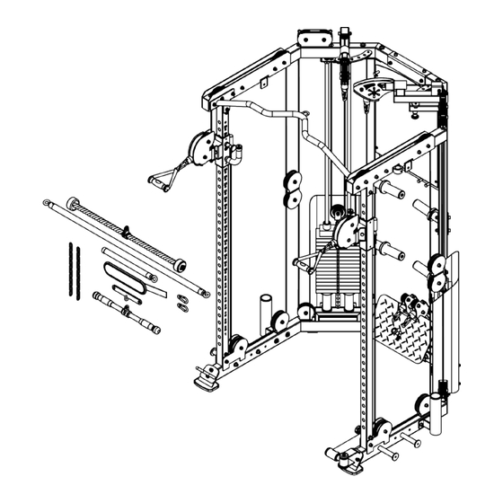
Page 2: Exploded View
EXPLODED VIEW... -
Page 3: Parts List
PARTS LIST Nº English description Specification Left Base Tube Right Base Tube Back Bracket Vertical Tube F50*2*1838.5 Upper Left Connection Frame Upper Right Connection Frame Left Rotating Frame Right Rotating Frame Handle Holder Left Back Upright Frame Right Back Upright Frame Left Barbell Stand Right Barbell Stand Pulley Frame... - Page 4 Shroud Fixing Plate 25*63.5*100*5 Guide-rod Φ19*1768 Hanger L Plate 545*50*30*3 Anti-friction Stickers 60*25*0.5 Pulley Sleeve Φ18*Φ10.2*18 Φ50 Shaft Cap Φ50*Φ11*8 Upper Cable Φ5*6450 Lower Cable Φ5*4815 L Plate with four holes 300*75*50*5 Knob Φ35*50*M10 Weight Stack Support Frame Pulley Frame Barbell Guard Plate 48*40*5 20+1 Selector Shaft...
- Page 5 Bumper Φ56*Φ20.5*5 Bumper Φ38*Φ7*15 Bumper Φ55*Φ26*5 Barbell Bumper Φ77*Φ47.5*13 Bumper Φ80*25 Bumper 60*50*6 Limit Sleeve Φ22*Φ10*8 Handle Sleeve Φ24*3*180(TPV) Front Guard Plate 58*38*5 Bearing Washer Φ30*Φ25.2*1 Shoulder Bolt Ф12.6*100*M10 Lat Pulldown Plate Long Rod Φ25*3*1220 Short Rod Φ25*3*375 Rope Φ28.5*915 12 Link Φ5*21*370 Ankle-cap...
- Page 6 Hex Socket-head Bolt M10*75 Hex Socket-head Bolt M10*80 Hex Socket-head Bolt M10*95 Hex Socket-head Bolt M10*100 Hex Bolt M6*15 Hex Bolt M10*45 Hex Counter-sunk Screw M6*10 Hex Counter-sunk Screw M8*25 Hex Counter-sunk Bolt M10*20 Phillips Counter-sunk Screw M5*10 Flat Washer Φ6.6*Φ12*1.6 Flat Washer Φ9*Φ16*1.6...
-
Page 7: Assembly Steps
ASSEMBLY STEPS Step 1-1. 1. Attach #1, #2 and #32 to #3 using: 2 #113 2 #118 6 #130 2 #137 2 #139 Do not tighten the bolts yet; NAME SPECIFICATION QUANTITY Left Base Tube Right Base Tube Back Bracket L Plate with two holes... - Page 8 Step 1-2. 1. Attach #16 to #3 using: 2 #107 Then tighten all the bolts (Note: After the foot pedal is installed, pull the handle of the adjustable frame to ensure that the foot pedal rotates smoothly) NAME SPECIFICATION QUANTITY Back Bracket Foot Pedal...
- Page 9 Step 2. 1. Install #18 and #9 on 2 #4, Pay attention to the adjustable frame is installed on the vertical tube to slide smoothly. 2. Install 2 #4 on #1 and #2 respectively using: 4 #118 2 #84 ...
- Page 10 Step 3. 1. Install #10 and #11 on #1 and #2 respectively using: 6 #112 6 #137 6 #130 Do not tighten the bolts yet; NAME SPECIFICATION QUANTITY Left Base Tube Right Base Tube Flat Washer Φ11*Φ20*2 Spring Washer Φ10 Left Back Upright Frame...
- Page 11 Step 4. 1. Install #5 on #4 and #10 using: 2 #120 1 #119 2 #132 4 #130 3 #139 Do not tighten the bolts yet; 2. Same way install #6 on #4 and #10, do not tighten the bolts yet. NAME SPECIFICATION QUANTITY...
- Page 12 Step 5. 1. Install 2 #46 on #5 and #6 using: 2 #118 2 #121 8 #130 4 #139 Do not tighten the bolts yet; 2. Install 2 #40 on #10 and #11 using: 4 #111 ...
- Page 13 Step 6. 1. Install 6 #30 on #29 using: 6 #122 6 #128 6 #135 Then tighten all the bolts. NAME SPECIFICATION QUANTITY Accessory Hanging Plate 500*685*33*3 Hanger Column Φ18*Φ12*35*M6 Hex Bolt M6*15 Flat Washer Φ6.6*Φ12*1.6 Spring Washer Φ6...
- Page 14 Step 7-1. 1. Install #29 to the illustrated position using: 4 #122 8 #128 4 #138 Do not tighten the bolts yet; NAME SPECIFICATION QUANTITY Accessory Hanging Plate 500*685*33*3 Hex Bolt M6*15 Flat Washer Φ6.6*Φ12*1.6...
- Page 15 Step 7-2. 1. First remove 2 #119, 4 #130 and 2 #139 that fixed #6, #5. 2. Install #9 to the illustrated position using: 6 #119 12 #130 6 #139 Do not tighten the bolts yet; 3. Tighten all the bolts, pay attention to tighten the machine to orderliness, strong, no loose phenomenon.
- Page 16 Step 8. 1. Install #23 on #1 using: 2 #113 2 #130 2 #137 Then tighten all the bolts; 2. Install #21 on #2 using: 2 #113 2 #130 2 #137 Then tighten all the bolts; NAME SPECIFICATION QUANTITY...
- Page 17 Step 9. 1. Install 4 #25 on #1 and #2 respectively using: 4 #114 4 #131 4 #137 Then tighten all the bolts. NAME SPECIFICATION QUANTITY Left Base Tube Right Base Tube Spring Washer Φ10 Bands peg Big Washer Φ10.6*Φ26*2 Hex Socket-head Bolt...
- Page 18 Step 10. 1. Install 2 #26 on #1 and #2 respectively using: 4 #117 4 #130 4 #132 4 #139 Then tighten all the bolts. NAME SPECIFICATION QUANTITY Left Base Tube Right Base Tube Flat Washer Φ11*Φ20*2 Flat Washer Φ10.5*Φ30*2.5...
- Page 19 Step 11. 1. Install 2 #12 on #10 using: 4 #118 8 #130 4 #139 Then tighten all the bolts; 2. Same way install 2 #13 on #11. NAME SPECIFICATION QUANTITY Hex Socket-head Bolt M10*75 Flat Washer Φ11*Φ20*2 Left Back Upright Frame Right Back Upright Frame...
- Page 20 Step 12-1. 1. Put 4 #78, 4 #48 and 4 #82 through 4 #39 respectively; 2. Install 4 #39 to the illustrated position respectively; NAME SPECIFICATION QUANTITY Bumper Φ56*Φ20.5*5 Weight Stack Support Frame Bumper Φ80*25 Guide-rod Φ19*1768...
- Page 21 Step 12-2. 1. Inclined the guide-rod, put 15 #61 from top to down through #39, then install 1 #52 on #39; As shown in the diagram III, remove M6*4 hex flat-head screw from 2 #77, then fixed #39 to #6 using 2 #77, finally put M6*4 hex flat-head screw back onto #77 and tighten all the bolts;...
- Page 22 Step 13. 1. Set aside 2 #15 for later use, remove the end of #44 according to diagram IV by unscrewing the M5*20 countersunk bolt and cable accessories K and L. Then, thread the steel cable through the designated positions shown in diagram a, b, c, d, e, f, j on the right side of the product in sequence. Finally, reassemble the cable accessories K and L along with the M5*20 countersunk bolt as diagram;...
- Page 23 Step 14. 1. Remove the end of #45 according to diagram VI by unscrewing the M5*20 countersunk bolt and cable accessories M and N; 2. Install #45 one end of the hollow bolt on #19 using #140 to tighten; 3. Thread #45 through the designated positions shown in diagram A, B, C, D, E, F on the right side of the product in sequence.
- Page 24 Step 15. 1. Install 2 #38 on #1 using: 4 #109 4 #128 4 #135 Do not tighten the bolts yet; 2. Install #36 on #38 using: 2 #109 2 #134 2 #135 Then tighten all the bolts; 3.
- Page 25 Step 16. 1. Install 6 #101 and 2 #62 to the illustrated position respectively; 2. Hang 1#90, 1#91, 1#94, 2#93, 1#92, 1#89 on #29. NAME SPECIFICATION QUANTITY Accessory Hanging Plate 500*685*33*3 Safety Hook Φ8*80 Handle Φ25*530 Long Rod Φ25*3*1220 Short Rod Φ25*3*375 Ankle-cap 340*90*10...
Need help?
Do you have a question about the GREENWICH and is the answer not in the manual?
Questions and answers