Advertisement
Quick Links
Advertisement

Related Manuals for ARCCAPTAIN MIG160


Summary of Contents for ARCCAPTAIN MIG160
- Page 1 Inverter Welding Machine MIG160 User Manual www.arccaptain.com...
- Page 2 Whatsapp: +19892449456 This manual is designed to help you get the most out of your ARCCAPTAIN products. Please save this manual and take time to read the safety warnings and precautions, assembly, operating, inspection, maintenance. They will help you protect yourself against potential hazards on the worksite.
- Page 3 CONTENTS 1. SAFETY............................1 1.1 General Safety..........................1 1.2 Electrical Safety........................1 1.3 Fire Safety..........................2 1.4 Fumes and Gases Safety....................... 2 1.5 Arc Rays and Noice Safety.....................2 1.6 Gas Shielded Welding – Cylinder Safety................3 1.7 Additional Safety Information....................3 2.
- Page 4 If you encounter any issues during installation or operation, refer to the relevant sections in this manual for inspection. If you're still unsure or unable to resolve the problem, please contact ARCCAPTAIN professional support. 1.1 General Safety Do NOT use the welder if the switch does not turn it on and off.
- Page 5 Only experts should replace machine parts. Avoid dropping foreign objects into the machine during component replacement. Ensure correct wire connections after replacing PCBs to prevent property damage. 1.3 Fire Safety WARINING BEWARE OF FIRE HAZARD! Place the machine on non-combustible surfaces to prevent fires.
- Page 6 2. PRODUCT INSTRUCTION 2.1 Function Overview This is MIG160, with advanced technology, perfect function and high performance. This ultra-portable welding system is suitable for various application needs. Synergic MIG: Automatically adjusts voltage and wire feeding speed based on wire diameter.
- Page 7 Conduct tips Ground clamp 10ft Electrode holder 10ft Gas hose 10ft Adapter 220V to 110V Operator’s manual For MIG160 2.3 Technical Parameters Model Technical Parameter Units MIG160 Rated input voltage AC110V±15% 50/60HZ AC220V±15% 50/60HZ Rated input power Rated input current 47.6...
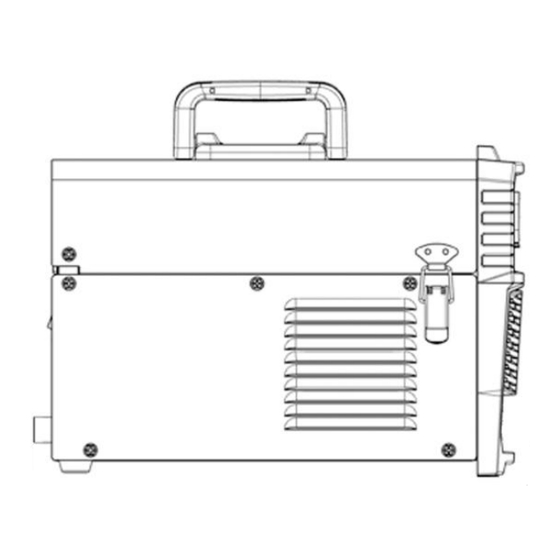
- Page 8 Figure 1 Size OPERATION CONTROL AND INSTRUCTIONS 3.1 Panel Instruction Part Picture 1.Positive Welding Terminal(+) 2. Negative Welding Terminal(-) 3. Current adjustment knob 4. Welding Mode Button 5. Wire Selection Button 6. Display Meter 7. MIG Torch Figure 2...
- Page 9 8.Power Switch 9. Cooling Fan 10. Power Input Cable 11. Gas Inlet Figure 3 3.2 Multi-function Digital Operation Description Figure 4 operation panel Detailed description for operation panel functions: Picture Description Item Function MIG diameter selection button Φ0.040 inch wire diameter LED...
- Page 10 Parameter switch button MIG LED Welding process selection area MMA LED Lift TIG LED Current adjustment knob Current adjustment Parameter LED display 3.3 Wire Feeding Description Part name Function Picture 1. Feed Fixed the Idler Arm and adjusts the...
- Page 11 It looks like the diagram below. Figure 6 Nameplate Duty cycle Rated duty cycle is the percentage of the ratio of operating time at rated Max output current to a 10-minute period. Voltage Function ①:MMA load curve 220V ②:TIG load curve...
- Page 12 Output characteristics Line Characteristics External characteristic curve of max output External characteristiccurve of mini output Rated load relationship Graph of output characteristic Figure 8 4. INSTALLATION AND CONNECTION ! WARINING BEWARE OF ELECTRIC SHOCK! Check and follow the instructions listed in the “Safety” section of this manual.
- Page 13 Description Picture 1. Continuously rotate the nozzle clockwise, as if pulling it upwards. Since the nozzle is spring-loaded internally, some force is required to remove it. NOTICE: ONLY TURN CLOCKWISE. Figure 9 2.Use a wrench to turn the tip of the contact nozzle counterclockwise.
- Page 14 2. Start to install the wire: Turn counterclockwise to remove the spool knob, then remove the spring. 3.Remove the spool plate, then spool spindle will be exposed. 4.Place the wire spool over the spool spindle. NOTICE: To prevent wire feed problems, set the leading...
- Page 15 Description Picture 1.Release Feed Tensioner and rotate the Idler Arm away from the Feed Roller. NOTICE: *Feed Tensioner knob could be turn counterclockwise to loosen it. Then, pull it down to remove tension. The spring-loaded Idler Arm will move upwards as illustrated.
- Page 16 6.Close the Idler Arm and turn down the Feed Tensioner until the idle roller presses down firmly on the wire. Now you may release the welding wire. Make sure the wire is positioned in the groove of the lower feed roller.
- Page 17 2. DO NOT touch internal Welder Components while it is plugged in. The MIG160 operates with a 110V or 220V power supply. Plug the Power Cord into a properly grounded. Set MIG Gun down on nonconductive, nonflammable surface away...
- Page 18 NOTE: For optimal performance, connect the MIG160 to a 50A branch circuit. If connected to a circuit with lower capacity, expect reduced welding current and duty cycle. The circuit must be equipped over 50A with delayed action-type circuit breaker or fuses.
- Page 19 4.Turn off the machine after the wire stick out. Then install the nozzle and contact tip. NOTE: Cut the wire 3/8” to 5/8” from the end of the tip. Figure 23 5.Turn on the machine. The machine is now ready to weld.
- Page 20 • Keep wire and liner clean. Do not use rusty wire. • Sharp bends or kinks in the welding cable should be avoided • ONLY use MIG solid welding wire. • MIG Welding parameters table(for reference only) 6. Operation for MIG Flux-Cored Welding...
- Page 21 2. DO NOT touch internal Welder Components while it is plugged in. The MIG160 operates with a 110V or 220V power supply. Plug the Power Cord into a properly grounded. Set MIG Gun down on nonconductive, nonflammable surface away from any grounded objects.
- Page 22 3. Press and hold the gun trigger to load the wire through the gun, until the wire feeds through the end of the Gun. NOTE: Before feeding, Remove the nozzle and contact tip before feeding the wire to ensure smooth wire feeding.
- Page 23 Turn the knob to find the required current Clamp the Ground clamp onto the workpiece, The Ground clamp must be securely connected to the workpiece. NOTICE: • Always weld clean, dry and well-prepared material. • Hold gun at a 45° angle to the workpiece with nozzle about 1/2”...
- Page 24 Description Picture 1. Connect the ground clamp to “-” Negative polarity NOTE: The ground clamp connecter MUST be tightly connected to the socket to avoid power short circuit. Ensure the ground clamp is connected on clean, bare metal (not rusty or painted).
- Page 25 NOTICE: The following steps require applying power to the Welder with the cover open. To prevent serious injury from fire or electric shock: 1.DO NOT touch anything, especially not the ground clamp, with the gun or welding wire or an arc will be ignited.
- Page 26 6. After the arc ignites: a. Lift the Electrode off workpiece the same distance as the diameter of the bare metal end. b. Tilt Electrode back 10 to 20 degrees. c. Drag Electrode to the back end of the weld puddle to deposit material as needed.
- Page 27 Picture Description 1. Connect the ground clamp to “+” Positive polarity NOTICE: The ground clamp connecter MUST be tightly connected to the socket to avoid power short circuit. Ensure the ground clamp is connected on clean, bare metal (not rusty or painted).
- Page 28 1/8" to 1/4" beyond the Ceramic Nozzle. NOTE: The tig torch and tungsten electrode are not included in the machine. If you need to purchase, please log in to the official website: WWW.ARCCAPTAIN.COM 7.5 Lift tig Welder Operation WARINING BEWARE OF ELECTRIC SHOCK!
- Page 29 NOTICE: The following steps require applying power to the Welder with the cover open. To prevent serious injury from fire or electric shock: 1.DO NOT touch anything, especially not the ground clamp, with the gun or welding wire or an arc will be ignited.
- Page 30 7. The initial settings may need to be adjusted after stopping and carefully inspecting the weld. Please refer to 6.7 Lift TIG Welding parameters table,Proper welding takes experience. 8. Open valve on TIG Torch to start gas flow. 9. To initiate welding arc, touch Electrode to work piece and lift.
- Page 31 Strap Installation 1. Thread the strap through the strap hole in front of the welder Figure 41 2. Thread the strap through the nylon buckle as shown in the diagram Figure 42 3. Thread the strap through the strap hole in back of...
- Page 32 5. The strap installation is complete Figure 45 MIG Basic Welding Technique WARINING BEWARE OF ELECTRIC SHOCK! NOTICE: The following steps require applying power to the Welder with the cover open. To prevent serious injury from fire or electric shock: 1.DO NOT touch anything, especially not the ground clamp, with the...
- Page 33 Figure 46 Travel Angel Travel angle is the right to left angle relative to the direction of welding. A travel angle of 5°- 15° is ideal and produces a good level of control over the weld pool. A travel angle greater that 20° will give an unstable arc condition with poor weld metal transfer, less penetration, high levels of spatter, poor gas shield and poor quality finished weld.
- Page 34 0.2-0.4in will produce a stable arc, and an even current flow providing good penetration and even fusion. Too short stick out will cause an unstable weld pool, produce spatter and over heat the contact tip. Too long stick out will cause an unstable arc, lack of penetration, lack of fusion and increase spatter.
- Page 35 Make sure that the entire Mig gun is completely cool and that the power cord is unplugged from the electrical outlet before proceeding. Torch accessories are consumables, ARCCAPTAIN provided more for your replacement. 10.2 Daily maintenance The power of the switching box and the welding machine should be shut down before daily checking (except appearance checking without contacting the conductive body) to avoid personal injury accidents such as electric shock and burns.
- Page 36 Whether the cable is drawn by an external force; MIG gun Whether the cable connected to the workpiece is well connected. 11. TROUBLESHOOTING ! WARINING...
- Page 37 Output heat range is too high. Set the knob to low Bead does not penetrate Feeding speed is inconsistent. Decrease and maintain a base metal. constant feeding speed. Output heat range is too low. Set the knob to high Wire sputters and sticks to The wire is damp.
- Page 38 The wire feeder fails. Repair it. The control PCB or wire feeding power PCB inside the machine Replace it. fails. The pressure arm on the wire Adjust it to get proper pressure. The welding current is feeder is not properly adjusted.
- Page 39 ● Replace wire with one of better quality severely ●Welding wire is of poor quality If you do not understand or are unable to perform the Recommended Course of Action safely, contact arccaptain.com for after-sale service. Save for future reference: Product: Date Purchased:...
- Page 40 Appendix:QUICK SET-UP GUIDE...
Need help?
Do you have a question about the MIG160 and is the answer not in the manual?
Questions and answers