Advertisement
Quick Links
Advertisement

Subscribe to Our Youtube Channel
Related Manuals for ARCCAPTAIN MIG250


Summary of Contents for ARCCAPTAIN MIG250
- Page 1 Inverter Welding Machine MIG250 User Manual www.arccaptain.com...
- Page 2 Whatsapp: +19892449456 This manual is designed to help you get the most out of your ARCCAPTAIN products. Please save this manual and take time to read the safety warnings and precautions, assembly, operating, inspection, maintenance. They will help you protect yourself against potential hazards on the worksite.
- Page 3 CONTENTS 1. SAFETY............................1 1.1 General Safety..........................1 1.2 Electrical Safety........................1 1.3 Fire Safety..........................2 1.4 Fumes and Gases Safety....................... 2 1.5 Arc Rays and Noice Safety.....................2 1.6 Gas Shielded Welding – Cylinder Safety................3 1.7 Additional Safety Information....................3 2.
- Page 4 If you encounter any issues during installation or operation, refer to the relevant sections in this manual for inspection. If you're still unsure or unable to resolve the problem, please contact ARCCAPTAIN professional support. 1.1 General Safety Do NOT use the welder if the switch does not turn it on and off.
- Page 5 Only experts should replace machine parts. Avoid dropping foreign objects into the machine during component replacement. Ensure correct wire connections after replacing PCBs to prevent property damage. 1.3 Fire Safety WARINING BEWARE OF FIRE HAZARD! Place the machine on non-combustible surfaces to prevent fires.
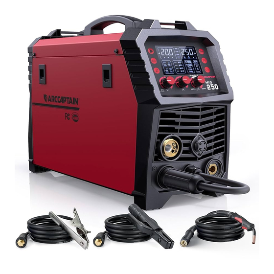
- Page 6 2. PRODUCT INSTRUCTION 2.1 Function Overview This is MIG250, with advanced technology, perfect function and high performance. This ultra-portable welding system is suitable for various application needs. 6 in 1 Multi-functions: Gas MIG/Gasless MIG/MMA /TIG/Spot welding/Spool Gun are available.
- Page 7 Conduct tips Ground clamp 10ft Electrode holder 10ft Gas hose 10ft Adapter 220V to 110V Rollers Operator’s manual For MIG250 2.3 Technical Parameters Model Technical Parameter Units MIG250 Rated input voltage AC110V±15% 50/60HZ AC220V±15% 50/60HZ Rated input power Rated input current 47.6...
- Page 8 Enclosure class Power factor COSφ 0.72 Insulation class Standard ANSI/NEMA/IEC 60974-1 Noise <70 Dimension inch 20.3x8.1x15.2 Weight kg/lb 20.5lb 1/16”-1/8” 1/16”-5/32”” Applicable electrode/wire inch 0.023”/0.030”/0.035” 0.023”/0.030”/0.035”/0.040” Figure 1 Size OPERATION CONTROL AND INSTRUCTIONS 3.1 Panel Instruction Part Picture...
- Page 9 1. Digital screen display area 2. Parameter setting and display area for spot welding time, parameter group storage, voltage and so on 3. Welding process selection area 4. MIG diameter selection area 5. Voltage and spot welding time adjustment knob 6.
- Page 10 3.2 Multi-function Digital Operation Description Figure 6 operation panel Detailed description for operation panel functions: Picture Description Item Function VRD LED VRD, Input Input voltage is 110V ,Remote voltage Input voltage is 220V control LED Spool gun remote control is connected...
- Page 11 MIG “synergic”LED The LED is on when the machine is in “synergic” Welding process selection button MMA LED Welding process Lift TIG LED selection area MIG LED MIG spool gun LED MIG operation mode selection button MIG operation 2T LED...
- Page 12 “ ” for Bum-back time adjustment. Bum-back time, Welding current adjustment in MIG Current and wire “synergic” mode feed speed Wire feed speed adjustment in MIG adjustment knob “separated” mode Welding current adjustment in MMA mode...
- Page 13 Attention Attention! Please select welding functions according to welding requirements. During welding, choose proper welding process and parameters according to the technology requirements of workpiece. With improper welding process and parameters, there will be unstable arc, excessive spatter and wire and electrode sticking during welding.
- Page 14 The duty cycle of your new welder can be found on the data plate affixed to the machine. It looks like the diagram below. Figure 8 Nameplate Duty cycle Rated duty cycle is the percentage of the ratio of operating time at rated Max output current to a 10-minute period.
- Page 15 Output characteristics Line Characteristics External characteristic curve of max output External characteristiccurve of mini output Rated load relationship Graph of output characteristic Figure 10 4. INSTALLATION AND CONNECTION ! WARINING BEWARE OF ELECTRIC SHOCK! Check and follow the instructions listed in the “Safety” section of this manual.
- Page 16 If it's also rusty, get rid of the whole spool. 4.2 Checking the Torch Accessories ! WARINING DO NOT set up without SWITCH OFF ! Before welding, verify that the contact tip size in your MIG torch matches your welding wire type.
- Page 17 Description Picture 1.Pull up on the Door Latch, then open the Door. Then you will see Wire Spool and wire feeder. Figure 14 Door latch 2. Start to install the wire: Turn counterclockwise to remove the spool knob. 3.Remove the spool plate, then spool spindle will be exposed.
- Page 18 Description Picture 1.Release Feed Tensioner and rotate the Idler Arm away from the Feed Roller. NOTICE: *Feed Tensioner knob could be turn counterclockwise to loosen it. Then, pull it down to remove tension. The spring-loaded Idler Arm will move upwards as illustrated.
- Page 19 6.Close the Idler Arm and turn down the Feed Tensioner until the idle roller presses down firmly on the wire. Now you may release the welding wire. Make sure the wire is positioned in the groove of the lower feed roller.
- Page 20 2. DO NOT touch internal Welder Components while it is plugged in. The MIG250 operates with a 110V or 220V power supply. Plug the Power Cord into a properly grounded. Set MIG Gun down on nonconductive, nonflammable surface away...
- Page 21 NOTE: For optimal performance, connect the MIG250 to a 50A branch circuit. If connected to a circuit with lower capacity, expect reduced welding current and duty cycle. The circuit must be equipped over 50A with delayed action-type circuit breaker or fuses.
- Page 22 4.Turn off the machine after the wire stick out. Then install the nozzle and contact tip. NOTE: Cut the wire 3/8” to 5/8” from the end of the tip. Figure 25 5.Turn on the machine. The machine is now ready to weld.
- Page 23 Select Bum-back time You can also choose to use the default Settings Function with separated Part Select Select MIG Close SYN Turn the knob to find the required voltage Turn the knob to find the required IPM Select 2T / 4T / Spot...
- Page 24 • Keep wire and liner clean. Do not use rusty wire. • Sharp bends or kinks in the welding cable should be avoided • ONLY use MIG solid welding wire. • MIG Welding parameters table(for reference only) Figure 27 6.
- Page 25 Loosen Spool Tension Nut. Install Spool so wire will feed clockwise. Tighten Spool Tension Nut until Spool cannot spin freely. Figure 30 Open Wire Feed Cover. Pull up on Feed Tensioner, then swing up and over to expose ...
- Page 26 3. Connect the polarity changeover plug to “+” Positive polarity NOTICE: The polarity changeover plug MUST be tightly connected to the socket to avoid power short circuit. 4. Connect the spool gun control line to socket and tighten it.
- Page 27 The MIG250 operates with a 110V or 220V power supply. Plug the Power Cord into a properly grounded. Set MIG Gun down on nonconductive, nonflammable surface away from any grounded objects. And then then turn the Power Switch ON.
- Page 28 3. Press and hold the gun trigger to load the wire through the gun, until the wire feeds through the end of the Gun. NOTE: Before feeding, Remove the nozzle and contact tip before feeding the wire to ensure smooth wire feeding.
- Page 29 Turn the knob to find the required IPM Select 2T / 4T / Spot If you select spot mode Please adjust the spot time Select inductance level Select Bum-back time You can also choose to use the default Settings NOTICE: •...
- Page 30 1.DO NOT touch anything, especially not the ground clamp, with the gun or welding wire or an arc will be ignited. 2. DO NOT touch internal Welder Components while it is plugged in. The MIG250 operates with a 110V or 220V power supply. Plug the Power Cord into a...
- Page 31 Set MIG Gun down on nonconductive, nonflammable surface away from any grounded objects. And then then turn the Power Switch ON. NOTE: For optimal performance, connect the MIG250 to a 50A branch circuit. If connected to a circuit with lower capacity, expect reduced welding current and duty cycle.
- Page 32 3. Press and hold the gun trigger to load the wire through the gun, until the wire feeds through the end of the Gun. NOTE: Before feeding, Remove the nozzle and contact tip before feeding the wire to ensure smooth wire feeding.
- Page 33 Select Flux-Cored Turn the knob to find the required current Select 2T / 4T / Spot If you select spot mode Please adjust the spot time Select inductance level Select Bum-back time You can also choose to use the default Settings Clamp the Ground clamp onto the workpiece, The Ground clamp must be securely connected to the ...
- Page 34 Figure 44 8. Operation for MMA and TIG ! WARINING DO NOT set up without SWITCH OFF ! MMA Welder Cable Connection NOTICE: Before setting up or using this product for new function, make sure to read the entire Important Safety Information section at...
- Page 35 4. Place the bare metal end of the Stick Electrode (sold separately) inside the jaws of the Electrode Holder. NOTE: Set Electrode Holder down on nonconductive, nonflammable surface away from any grounded objects. Install Stick Electrode with the machine turned off.
- Page 36 3. Turn the Power Switch ON. The Operation interface will light up and the Cooling fan will rotate. NOTE: Welder is now energized and open circuit Voltage is present. Figure 48 4. Select MMA 5. Stroke the workpiece lightly to ignite the arc.
- Page 37 8.4 Lift TIG Welder Cable Connection WARINING BEWARE OF ELECTRIC SHOCK! NOTICE: The following steps require applying power to the Welder with the cover open. To prevent serious injury from fire or electric shock: 1.DO NOT touch anything, especially not the ground clamp, with the...
- Page 38 1. With assistance, place an 100% Argon cylinder (not included) onto a cabinet or cart near the Welder and secure the cylinder in place with two straps (not included) to prevent tipping.
- Page 39 1/8" to 1/4" beyond the Ceramic Nozzle. NOTE: The tig torch and tungsten electrode are not included in the machine. If you need to purchase, please log in to the official website: WWW.ARCCAPTAIN.COM 8.5 Lift tig Welder Operation WARINING BEWARE OF ELECTRIC SHOCK! NOTICE: The following steps require applying power to the Welder with the cover open.
- Page 40 NOTE: Turn the Power Switch off before connecting Power Cord. Plug the Power Cord into a properly grounded and rated receptacle that matches the plug. The circuit must be equipped with delayed action-type circuit breaker or fuses.
- Page 41 15. Turn the Power Switch OFF. 16. To prevent accidents, after use: • Allow Welder to cool down. • Unplug Welder’s power cord from outlet. • Remove Ground Clamp from workpiece or table. • Disconnect TIG Torch and Ground Cables.
- Page 42 A default set of common welding parameters for this machine can be revised by revising system parameters in case of need. Below is method: NOTE: The default parameters of the welder are modified for experienced welders. The default parameters of the welder have been set in the best state. Do not change the ...
- Page 43 MMA mode Setting Function parameters Default Unit Description range Background parameters Restore factory default initialization (Select “1” to restore factory default) P2 Welding time calculation 0.0~999 Calculate welding time VRD switch at MMA P3 VRD switch at MMA ( “0”: VRD is off, “1”:VRD is on)...
- Page 44 10.1 Basic MIG Welding Good weld quality and profile depend on factors like gun angle, travel direction, electrode extension (stick out), feeding speed, base metal thickness, wire feed speed (amperage), and arc voltage. Here are some basic guidelines to help with your setup: Gun Position and Travel Direction ...
- Page 45 Figure 56 Angle to Work The work angle is the forward back angle of the gun relative to the work piece.The correct work angle provides good bead shape, prevents undercut, uneven penetration, poor gas shield and poor quality finished weld.
- Page 46 10.2 Feeding Speed Feeding speed refers to how quickly the gun is moved along the weld joint, measured in inches per minute. It can vary based on conditions and the welder's skill, limited by their ability to control the weld pool.
- Page 47 Make sure that the entire Mig gun is completely cool and that the power cord is unplugged from the electrical outlet before proceeding. Torch accessories are consumables, ARCCAPTAIN provided more for your replacement. 11.2 Daily maintenance The power of the switching box and the welding machine should be shut down before daily checking (except appearance checking without contacting the conductive body) to avoid personal injury accidents such as electric shock and burns.
- Page 48 Items Checking requirements Remarks Earth Whether the grounding wires (including workpiece If unqualified, tighten or cable Earth wire and welding machine earth wire) break off. replace the components. Whether the insulating layer of the cable is worn, or the...
- Page 49 Problem (symptoms) Possible areas of Recommended course of mis-adjustment action Feeding speed is slow and/or Increase and maintain a Bead is too inconsistent constant feeding speed. thick(intermittently) Output heat range is too high. Set the knob to low Bead does not penetrate Feeding speed is inconsistent.
- Page 50 There is output current when pushing the torch The wire feeder is clogged. Unclog it. trigger to feed gas, but the wire feeder does not work. The wire feeder fails. Repair it. The control PCB or wire feeding power PCB inside the machine Replace it.
- Page 51 ● Replace wire with one of better quality severely ●Welding wire is of poor quality If you do not understand or are unable to perform the Recommended Course of Action safely, contact arccaptain.com for after-sale service. Save for future reference: Product: Date Purchased:...
Need help?
Do you have a question about the MIG250 and is the answer not in the manual?
Questions and answers
No it has the 205 and 200 specific and says you have to get a hold of arccaption toget the proper foot control for the 250 model no where does it state what is the correct in part no for foot control tig
What is the proper part no. For my recently pursched ark captian 250 tig foot control upgrade