Advertisement
- 1 SAFETY
- 2 Symbol Description
- 3 INTRODUCTION
- 4 INSTALLATION
- 5 OPERATION
- 6 MAINTENANCE
- 7 STRAP INSTALLATION
-
8
TROUBLESHOOTING
- 8.1 Bead is too thick (intermittently)
- 8.2 Bead does not penetrate base metal
- 8.3 Wire sputters and sticks to workpiece
- 8.4 Edge of weld has ragged depressions
- 8.5 There is no current after turning on the machine
- 8.6 The fan does not work during welding
- 8.7 The overheating indicator is on
- 8.8 The welding current is unstable
- 9 WIRING DIAGRAM
- 10 Documents / Resources
SAFETY
Welding may cause damage to you and others. Please take good protection during welding. Please refer to the operator safety guidelines in conformity with the accident prevention requirements of the manufacturer for more details.
 | Only qualified personnel can operate this machine!
|
 | Electric shock-may result in serious injury or even death!
|
 | Fume and gases can be dangerous!
|
 | Arc rays can burn!
|
 | Improper operation may cause fire or explosion.
|
 | Weld materials can burn.
|
 | Excessive noise can be harmful to hearing.
|
 | Magnetic field can be harmful to pacemakers.
|
 | Moving parts may injure your body.
|
 | Asking for professional support while trouble strikes.
|
Symbol Description
 | Cautions in operation |
 | Items need special instruction |
 | It's forbidden to dispose electric waste with other ordinary waste. Please take care of our environment. |
INTRODUCTION
ARCCAPTAIN welder was built by high quality components, every single unit machine was passed multiple industry leading laboratory tests to provide a great welding experience and performance.
For your safety, please read and understand this manual carefully before using this product. Your satisfaction is our priority! For any question or concerns, please do not hesitate to contact ARCCAPTAIN for SUPPORT: service@arccaptain.com

How To Use This Manual
To ensure safe operation, read the entire manual, including the chapter on safety instructions and warnings.
Receipt of Equipment
When you receive the equipment, check it against the invoice to make sure it is complete and inspect the equipment for possible damage due to shipping. If there is any damage, notify the carrier immediately to file a claim. Furnish complete information concerning damage claims or shipping errors to the location in your area listed in the inside back cover of this manual. Include all equipment identification numbers as described above along with a full description of the parts in error. Move the equipment to the installation site before un-crating the unit. Use care to avoid damaging the equipment when suing bars, hammers, etc., to nu-crate the unit.
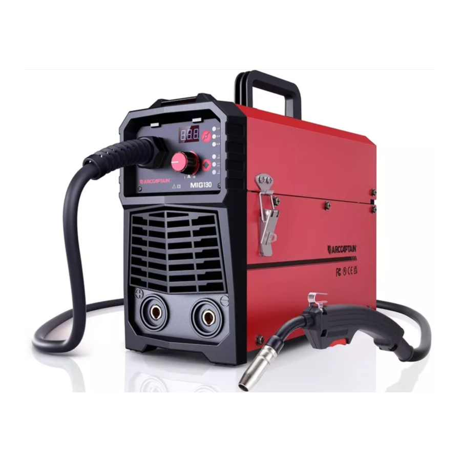
Description
This MIG130 takes the guess work out of welding with an impressive SYNERGIC SET function that allows the user to weld like a Pro with no previous welding experience necessary.
Duty Cycle
The rated duty cycle of a welding power source, is a statement of the time it may be operated at its rated welding current output without exceeding the temperature limits of the insulation of the component parts. To explain the 10 minute duty cycle period the following example is used. Suppose a welding power source is designed to operate at a 20% duty cycle, 120 amperes at 20 volts. This means that it has been designed and built to provide the rated amperage (120A) for 2 minutes, i.e. Arc welding time, out of every 10 minute period (20% of 10 minutes is 2minutes). During the other 8 minutes of the 10 minute period the welding power source must idle and be allowed to cool.
Specifications
| Items | Models |
| MIG130 | |
| Rated input voltage | Single-phase AC110V 50Hz/60Hz |
| Rated input power (KVA) | 5 |
| Welding current range(MIG,MMA,TIG) | 20-130A |
| Welding voltage range (MIG,MMA,TIG) | 16-20.5V (MIG) 20.8-25.2V(MMA) 10.8V-15.2V(TIG) |
| Rated duty cycle | 60% |
| No-load voltage (V) | 65 |
| Applicable wire/electrode | 0.8/0.9/1.0mm 1.6-3.2mm (1/16"-1/8") |
| Housing protection grade | IP21S |
| Insulation grade | H |
| Power factor(COSφ) | 0.68 |
| Cooling mode | Air cooling |
| Overall efficiency | 85% |
| Dimension | 380*135 *247 mm 14.9*5.3*9.7 in |
| Weight | 5.35kg/11.79lb |
INSTALLATION
Environment and Location
- Safety Precautions
Do not attempt to use this equipment until you have thoroughly read all installation, operating and maintenance information supplied with your equipment. They include important safety precautions and detailed operating and maintenance instructions. - Electric Shock Can Kill
- Only qualified personnel should Perform this installation.
- Do not touch electrically live parts.
- Always connect the machine to an earthed mains supply.
- Select Suitable Location
Place the welder where clean cooling air can freely circulate in and out of the front & rear louver vents. Dirt, dust or any foreign material that can be drawn through vents into welder must be kept to a minimum. Failure to observe these precautions can result in excessive operating temperatures which can lead to plant failure. - Grinding
Do not direct grinding particles towards the welder. An abundance of conductive material can cause plant failure. - Stacking
This machine cannot be stacked. - Transport Unloading
Never underestimate the weight of equipment, never move of leave suspended in the air above people.
Falling equipment can cause injury. Never lift welder with gas bottle attached. Never lift above personnel. - Tilting
Machine must be placed on a secure level surface.
Do not place or operate this machine on a surface with an incline greater than 15º from horizontal.
The machine may topple over if this procedure is not followed. - Environmental Rating
The welding power source carries the IP21S rating. It may be used in normal industrial and commercial environments. Avoid using in areas where water / rain is around..
Read and follow the "Electric Shock Warnings' in the safety section if welding must be performed under electrically hazardous conditions such as welding in wet areas or water on the work piece.
The high frequency generator being similar to a radio transmitter may cause interference to radio, TV and other electronic equipment.
These problems may be the result of radiated interference. Proper grounding methods can reduce or eliminate this. - Radiated interference can develop in the following ways
- Direct interference from welder power source
- Direct interference from the welding leads
- Direct interference radiated from feedback into power lines
- Interference from re-radiation by ungrounded metallic objects
- Keeping these contributing factors in mind, installing equipment as per following instructions should minimize problems
- Keep the welder input power lines as short as possible and enclose as much of them as possible in metal conduit or equivalent shielding. There should be a good electrical contact between this conduit and ground(Earth).
- Keep the work and electrode leads as short as possible. Tape the leads together where practical.
- Be sure the torch and earth leads rubber coverings are free from cuts and cracks that allow welding power leakage.
- Keep earth lead connection to work in good condition clean area on workbench where earth clamp is situated on a regular basis.
- Ventilation
This machine can create powerful welding current and has strict cooling requirements that cannot be met with natural ventilation. Therefore machine to work stable with effective cooling. The minimum distance between the machine and nearby objects should be 20mm.
Input Power Connection
- The machine has one input connection, the power input cable. The power input cable is located on the rear.
- The MIG130(N2HAB) is provided with a 110V cables, 2.0M in length, with a 16Amp 5-15P plug molded onto the cord;
- The MIG130(N2A9) is provided with a 230V cables, 2.0M in length, with a 16Amp 5-15P plug molded onto the cord.
- The MIG130(N2A8) is provided with a 110V/220V cables, 2.0M in length, with a 16Amp 5-15P plug molded onto the cord;
- The rated output of the MIG130 is available when connected to a 40A branch circuit.when connected to a branch circuit with lower capacity, lower welding current and duty cycle must be used.
- The primary cable should be tightly connected to the correct socket to avoid oxidization.
- Check whether the voltage value varies in acceptable range with a multi-meter.
- The mains supply voltage should be within ±15% of the rated mains supply voltage. Too low a voltage may cause poor welding performance. Too high a supply voltage will cause components to overheat and possibly fail.
Code Requirements for Electrical Input Connections
This welding machine must be connected to a power source in accordance with applicable electrical codes.
The National Electrical Code provides standards for amperage handling capability of supply conductors based on duty cycle of the welding source.
If there is any question about the installation meeting applicable electrical code requirements, consult a qualified electrician.
Do not remove the power cord ground prong.
Features
- Front Panel Layout Description

- Back Panel Layout Description

- Operation interface Description


- Positive Welding Terminal(+)
- Negative Welding Terminal(-)
- Synergic knob
- Welding mode button
- Wire selection button
- Display Meter
- MIG Torch
- Power Switch
- Cooling FAN
- Power Input Cable
- Welding mode MIG/MMA/TIG LED
- Wire selection 0.8/0.9/1.0 LED
Wire Loading and Threading
Turn machine power switch to the OFF("0")position before working inside the wire feed enclosure.
Make sure that the wire feed drive roll and the contact tip of the gun match the diameter and type of wire used.
Installation of Wire Spool

- Push the spool onto the spindle so that the wire deeds off the bottom of the spool, toward the drive roll.
- Push the spool spacer onto the spindle, against the spool.
- Slide the spring onto the spool, them press on the spool lock, turning it clockwise to lock the spool assembly onto the spindle.
Wire Threading Details
- Release the spring loaded thumb screw and rotate the idle roll arm away from the wire deed drive roll. Ensure that the visible, stenciled size on the drive roll side facing you matches the wire size being used.
- Carefully detach the end of the wire from the spool. Maintain tension on the wire to prevent the spool from unwinding and do not release the wire until after step8.
- Cut the bent portion of wire off and straighten the first 4"(100mm).
- Thread the wire through the incoming guide tube, over the drive roll, and into the gun liner.
- Close the idle roll arm and turn down the thumbscrew until the idle roller presses down firmly on the wire. (Now you may release the welding wire ). Make sure the wire is positioned in the groove of the lower drive roll.
- The spring loaded thumbscrew on the idle roll arm adjusts the pressure on the wire. Adjust pressure by turning the thumbscrew to prevent spool overrun, but still allow smooth and easy wire deeding. Start with the pressure set to an intermediate value. Readjust, if necessary. If the drive roll slips while feeding wire, the pressure should be increased until the wire feeds properly.
When feeding the welding wire through the gun, the drive roll, the gun connector block and the gun contact tip are always energized relative to work and ground.
Wire Stick Out

- Remove the contact tip and nozzle from the gun.
- Turn the machine ON("1").
- Straighten the gun cable assembly.
- Depress the gun trigger switch and feed welding wire through the gun and cable. (Point the gun away from yourself and others while feeding wire). Release the gun trigger after wire appears at the end of the gun.
- Turn off the machine.
- Install the nozzle and contact tip. Refer to Figure 4. Cut the wire off so the 3/8" to 5/8"(10-15mm) protrudes from the end of the tip.
- Turn on the machine. The machine is now ready to weld.
OPERATION
Read and understand this entire section before operating your machine.
Safety Precautions
Do not attempt to use this equipment until you have thoroughly read all operating and maintenance manuals supplied with your equipment and any related welding machine it will be used with. They include important safety precautions, operating and maintenance instructions and parts lists.
Electric Shock can kill.

- Do not touch electrically live parts such as output terminals or internal wiring.
- Insulate yourself from the work and ground.
- always wear dry insulating gloves.
Welding Sparks can cause Fire or Explosion

- Keep flammable material away.
- Do not weld upon containers which Held combustibles.
Arc Rays can Burn

- Wear eye, ear and body protection.
Fumes and Gases can be Dangerous.
Although the removal of the particulate matter from welding smoke may reduce the ventilation requirement, concentrations of the clear exhausted fumes and gases may still be hazardous to health. Avoid breathing concentrations of these fumes and gases. Use adequate ventilation when welding.
Installation and Setup For MIG with Gas less
- Switch the Power Source ON/OFF switch located on the rear of the power source to the OFF position.
- Connect the weld power cable to the Negative socket and tighten it.
- Connect the earth cable plug into the Positive socket and tighten it.
![]()
Loose welding terminal connections can cause overheating and result in the male plug being fused in the terminal. Remove any packaging material prior to use. Do not block the air vents at the front or rear of the Welding Power Source - Check the Weld Power Cable is connected to the Negative terminal.
- Fit the correct size Knurled drive roller for Gas less Flux Core wire.
- Place the Wire Spool onto the Spool Holder-Note: the spool retaining nut is top thread. Snip the wire from the spool being sure to hold the wire to prevent rapid uncoiling. Feed the wire into the wire feeder inlet guide tube through to the drive roller.
- Carefully feed the wire over the drive roller into the outlet guide tube, feed through about 150mm into.
- Align the wire into the groove of the drive roller and close down the top roller making sure the wire is in the groove of the bottom drive roller, lock the pressure arm into place.
- Apply a light amount of pressure to the drive roller. Too much pressure will crush the cored wire.
- Remove the gas nozzle and contact tip from the torch neck.
- Switch the Power Source ON/OFF switch located on the rear of the Power Source to the ON position and the green LED in the front panel is illuminated.
- Press and hold the MIG Torch switch to feed the wire through to the torch neck.
- Fit the correct sized contact tip and feed the wire through it, screw the contact tip into the tip holder of the torch head and nip it up tightly.
- Not install the gas nozzle to the torch head.
- Select the correct sized wire diameter.
- Select welding parameter required on 'synergic' knob, based on the material, thickness of the work piece.


- Power Switch
- Connect it to the negative socket
- [3/4] Connect earth lead to +
- Fit the correct sized Knurled Driver roller for Gas Less Flux Cored wire

- Place wire onto spool holder(spool retaining nut is top thread) Feed the wire through the inlet guide tube on to the drive roller

- [7-9]Close down the top roller bracket and clip the pressure arm into place. Apply a medium amount of pressure to the drive roller


- Remove the gas nozzle and contact tip from the front end of the MIG torch
![]()

[13/14]Fit the correct size contact tip over the wire and fasten tightly into tip holder

[15/16] Select the correct sized wire diameter and set the welding parameter

NOTE!
Flux core / Gas less wire don't use for a long time(more than 3days) need to store sealed.
The recommended electrode for the flux-cord, self-shielded process are 0.8 or 0.9mm diameter spools.
Flux-cord wire is excellent for single-pass lap, fillet and butt welding of thin gauged galvanised and mild steels.
FCAW Basic Welding Technique
FLUX CORED ARC WELDING(FCAW):This is an electric arc welding process which fuses together the parts to be welded by heating them with an arc between a continuous flux filled electrode wire and the work. Shielding is obtained through decomposition of the flux within the tubular wire. Additional shielding may or may not be obtained from an externally supplied gas or gas mixture. The process is normally applied semi automatically; however the process may be applied automatically or by machine. It is commonly used to weld large diameter electrodes in the flat and horizontal position and small electrode diameters in all position. The process is used to a lesser degree for welding stainless steel and for overlay work.
Weld at a Steady Pace do not weave the arc, neither forward, backward, of sideways remove slag with the Chipping Hammer to expose weld for Horizontal Weld Joins.
Remember: Drag if there's Slag, Refer to manual for Troubleshooting Poor Weld Quality.
Adjustable Variables
- Stick-out (distance between the end of the contact tube (tip) and the end of the electrode wire). Maintain at about 10mm stick-out.
- Wire Feed Speed. Increase in wire feed speed increases weld current, Decrease in wire feed speed decreases weld current.
- Nozzle Angle. This refers to the position of the welding gun in relation to the joint. The transverse angle is usually one half the included angle between plates forming the joint. The longitudinal angle is the angle between the center line of the welding gun and a line perpendicular to the axis of the weld. The longitudinal angle is generally called the Nozzle Angle and can be either trailing (pulling) or leading (pushing). Whether the operator is left handed or right handed has to be considered to realize the effects of each angle in relation to the direction of travel.
Establishing the Arc and Making Weld Beads
- Before attempting to weld on a finished piece of work, it is recommended that practice welds be made on a sample metal of the same material as that of the finished piece.
- The easiest welding procedure for the beginner to experiment with MIG welding is the flat position. The equipment is capable of flat, vertical and overhead positions.
- For practicing MIG welding, secure some pieces of 1.5mm or 2.0mm mild steel plate 150X 150mm. Use 0.8mm flux cored gas less wire or a solid wire with shielding gas.
Basic MIG Welding
Good weld quality and weld profile depends on gun angle, direction of travel, electrode extension (stick out), travel speed, thickness of base metal, wire feed speed (amperage) and arc voltage. To follow are some basic guides to assist with your setup.
- Gun Position -ravel Direction, Work Angle
Gun position or technique usually refers to how the wire is directed at the base metal, the angle and travel direction chosen. Travel speed and work angle will determine the characteristic of the weld bead profile and degree of weld penetration.- Push Technique
The wire is located at the leading edge of the weld pool and pushed towards the un-melted work surface. This technique offers a better view of the weld joint and direction of the wire into the weld joint. Push technique directs the heat away from the weld puddle allowing faster travel speeds providing a flatter weld profile with light penetration - useful for welding thin materials. The welds are wider and flatter allowing for minimal clean up / grinding time.
![]()
- Perpendicular Technique
The wire is fed directly into the weld, this technique is used primarly for automated situations or when conditions make it necessary. The weld profile is generally higher and a deeper penetration is achieved.
![]()
- Drag Technique
The gun and wire is dragged away from the weld bead. The arc and heat is concentrated on the weld pool, the base metal receives more heat, deeper melting, more penetration and the weld profile is higher with more build up.
![]()
- Push Technique
- Travel Angel
Travel angle is the right to left angle relative to the direction of welding. A travel angle of 5°- 15° is ideal and produces a good level of control over the weld pool. A travel angle greater that 20° will give an unstable arc condition with poor weld metal transfer, less penetration, high levels of spatter, poor gas shield and poor quality finished weld.

- Angle to Work
The work angle is the forward back angle of the gun relative to the work piece. The correct work angle provides good bead shape, prevents undercut, uneven penetration, poor gas shield and poor quality finished weld.

- Stick Out
Stick out is the length of the unmelted wire protruding from the end of the contact tip. A constant even stick out of 5-10mm will produce a stable arc, and an even current flow providing good penetration and even fusion. Too short stick out will cause an unstable weld pool, produce spatter and over heat the contact tip. Too long stick out will cause an unstable arc, lack of penetration, lack of fusion and increase spatter.


Travel Speed
Travel speed is the rate that the gun is moved along the weld joint and is usually measured in mm per minute. Travel speeds can vary depending on conditions and the welders skill and is limited to the welders ability to control the weld pool. Push technique allows faster travel speeds than Drag technique. Gas flow must also correspond with the travel speed, increasing with faster travel speed and decreasing with slower speed. Travel speed needs to match the amperage and will decrease as the material thickness and amperage increase.
- Too Fast Travel Speed
A too fast travel speed produces too little heat per mm of travel resulting in less penetration and reduced weld fusion, the weld bead solidifies very quickly trapping gases inside the weld metal causing porosity. Undercutting of the base metal can also occur and an unfilled groove in the base metal is created when the travel speed is too fast to allow molten metal to flow into the weld crater created by the arc heat. - Too Slow Travel Speed
A too slow travel speed produces a large weld with lack of penetration and fusion. The energy from the arc dwells on top of the weld pool rather than penetrating the base metal. This produces a wider weld bead with more deposited weld metal per mm than is required resulting in a weld deposit of poor quality. - Correct Travel Speed
The correct travel speed keeps the arc at the leading edge of the weld pool allowing the base metal to melt sufficiently to create good penetration, fusion and wetting out of the weld pool producing a weld deposit of good quality.
MMA and TIG Installation

- A primary power supply cable is available for this welding machine. Connect the power supply cable to the rated input power.
- The primary cable should be tightly connected to the correct socket to avoid oxidization.
- Check whether the voltage value varies in acceptable range with a multi-meter.
- Insert the cable plug with electrode holder into the "-" socket on the front panel of the welding machine, and tighten it clockwise.
- Insert the cable plug with earth clamp into the "+" socket on the front panel of the welding machine, and tighten it clockwise.
- Ground connection is needed for safety purpose. The connection as mentioned above in 4) and 5) is DCEN connection. Operator can choose DCEP connection according to workpiece and electrode application requirement. Generally, DCEP connection is recommended for basic electrode, while there is no special requirement for acid electrode.
- Insert the cable plug with TIG Welding torch into the "--" socket on the front panel of the welding machine, and tighten it clockwise.
- Insert the cable plug with earth clamp into the "+" socket on the front panel of the welding machine, and tighten it clockwise.
MAINTENANCE
Safety Matters
Risk of injury from electric shock!
Cleaning machines that are not disconnected from the mains can lead to serious injuries!
- Disconnect the machine completely from the mains.
- Remove the mains plug.
- Wait for 5 minutes until the capacitors have discharged.
Electric Shock can kill
- Turn the input power OFF at he welding power source before installation or changing drive rolls and/or guides.
- Do not touch electrically live parts.
- When inching with the gun trigger, electrode and drive mechanism are "hot" to work and ground and could remain energized several seconds after the gun trigger is released.
- Do not operate with covers, panels or guards removed or open.
- Only qualified personnel should perform maintenance work.
Items Requiring No Maintenance
- Drive Motor and Gearbox - Lifetime lubrication
- Wire Reel Spindle - Do NOT lubricate shaft
Routine and Periodic Maintenance
- Before Each Use -Check over machine and accessories for any obvious condition that may prevent safe performance or operation, repair or replace items as necessary to correct any abnormal condition.
AFTER 5 MINUTES OF WELDING OR WHEN SPATTER ACCUMULATES ON THE CONTACT
TIP:
- Cleaning Tip and Nozzle- With the power switch in the OFF position, keep the contact tip and nozzle clean to avoid are bridging between them. Bridging can result in a shorted nozzle, poor welds and an overheated gun. Hint: Anti-stick spray or gel, available from a welding supplier, may reduce buildup and aid in spatter removal.
Daily maintenance
The power of the switching box and the welding machine should be shut down before daily checking (except appearance checking without contacting the conductive body) to avoid personal injury accidents such as electric shock and burns.
- Daily checking is very important in keeping the high performance and safe operation of this welding machine.
- Do daily checking according to the table below, and clean or replace components when necessary.
- In order to ensure the high performance of the machine, please choose components provided or recommended by producer when replacing components.
Table 4-1: Daily checking of the welding machine
| Items | Checking requirements | Remarks |
| Front panel | Whether any of the components are damaged or loosely connected; Whether the output quick sockets are tightened; Whether the abnormity indicator illuminates. | If unqualified, check the interior of the machine, and tighten or replace the components. |
| Back panel | Whether the input power cable and buckle are in good condition; Whether the air intake is unobstructed. | |
| Cover | Whether the bolts are loosely connected. | If unqualified, tighten or replace the components. |
| Chassis | Whether the screws are loosely connected. | |
| Routine | Whether the machine enclosure has color fading or overheating problems; Whether the fan sounds normal when the machine is running; Whether there is abnormal smell, abnormal vibration or noise when the machine is running. | If abnormal, check the interior of the machine. |
| Cleaning the Feed Rolls | Clean the grooves in the drive rolls frequently. This can be done by using a small wire brush. Also wipe off, or clean the grooves on the upper feed roll. After cleaning, tighten the feed roll retaining knobs. | |
Table 4-2: Daily checking of the cables
| Items | Checking requirements | Remarks |
| Earth cable | Whether the grounding wires (including workpiece Earth wire and welding machine earth wire) break off. | If unqualified, tighten or replace the components. |
| Welding cable\ MIG gun | Whether the insulating layer of the cable is worn, or the conductive part of the cable is exposed; Whether the cable is drawn by an external force; Whether the cable connected to the workpiece is well connected. | Use appropriate methods according to the work site situation to ensure safety and normal cutting. |
Periodic Check
Periodic check should be carried out by qualified professionals to ensure safety. The power of the switching box and the welding machine should be shut down before periodic check to avoid personal injury accidents such as electric shock and burns. Due to the discharge of capacitors, checking should be carried out 5 minutes after the machine is powered off.
Tips:
 | Safety All maintenance and checking should be carry out after the power is completely cut off. Make sure the power plug of the machine is pulled out before uncovering the welding machine. When the machine is powered on, keep hands, hair and tools away from the moving parts such as the fan to avoid personal injury or machine damage. |
 | Periodic check Check periodically whether inner circuit connection is in good condition (esp. plugs). Tighten the loose connection. If there is oxidization, remove it with sandpaper and then reconnect. Check periodically whether the insulating layer of all cables is in good condition. If there is any dilapidation, rewrap it or replace it. |
 | Beware of static In order to protect the semiconductor components and PCBs from the static damage, please wear antistatic device or touch the metal part of the enclosure to remove static in advance before contacting the conductors and PCBs of the machine internal wiring. |
 | Keep it dry Avoid rain, water and vapor infiltrating the machine. If there is, dry it and check the insulation of the welding machine (including that between the connections and that between the connection and the enclosure) with an ohmmeter. Only when there are no abnormal phenomena anymore, can the machine be used. Put the machine into the original packing in dry location if it is not to be used for a long time. |
 | Pay attention to maintenance Periodic check should be carried out to ensure the long-term normal use of the machine. Be careful when doing the periodic check, including the inspection and cleaning of the machine interior. Generally, periodic check should be carried out every 6 months, and it should be carried out every 3 months if the welding environment is dusty or with heavy oily smoke. |
STRAP INSTALLATION
- Pull out one side through the strap hole on the back panel with hook side of the velcro up.
![]()
- Pull out it to well stick hook side of the velcro to loop side and across the nylon buckle. Repeat it on the other side.

- Repeat it on the front panel. Pull out one side through the strap hole on the back panel with hook side of the velcro up. Pull out it to well stick hook side of the velcro to loop side and across the nylon buckle.
![]()
- Proper state after installation:

- Strap does not twist;
- Buckle side of shoulder pad is up, while its flat side faces the machine (as shown in the picture);
- Straps are well locked.


TROUBLESHOOTING
How to use troubleshooting Guide
Service and Repair should only be performed by qualified authorized personnel; Unauthorized repairs performed on this equipment may result in danger to the technician and machine operator and will invalidate your factory warranty. For your safety and to avoid Electrical Shock, please observe all safety noted and precautions detailed throughout this manual. When replacing parts, use only original spare parts. When ordering spare parts, please quote the machine type, serial number and item number of the machine, as well as the type designation and item number of the spare part.
Troubleshooting Guide is provided to help you locate and repair possible machine malfunctions. Simply follow the three step procedure listed below.
- Locate Problem(Symptom)
Look under the column labeled "PROBLEM(SYMPTOMS)". This column describes possible symptoms that the machine may exhibit. Find the listing that best describes the symptom that the machine is exhibiting. - Possible Cause
The second column labeled "POSSIBLE CAUSE" lists the obvious external possibilities that may contribute to the machine symptom. - Recommended Course of Action
This column provides a course of action for the Possible Cause, generally it states to contact you local after-sales service center.
If you do not understand or are unable to perform the Recommended Course of Action safely, contact your local after-sales service center. - Electric Shock can kill
Turn off machine at the disconnect switch on the rear of the machine and remove main power supply connections before doing any troubleshooting. - Observe all Safety Guidelines detailed throughout this manual
| Problem (symptoms) | Possible areas of mis-adjustment | Recommended course of action |
Bead is too thick (intermittently) | Travel speed is slow and/or inconsistent | Increase and maintain a constant travel speed. |
| Output heat range is too high. | Set the knob to low | |
Bead does not penetrate base metal | Travel speed is inconsistent. | Decrease and maintain a constant travel speed. |
| Output heat range is too low. | Set the knob to high | |
Wire sputters and sticks to workpiece | The wire is damp. | Change to dry wire. Be sure wire is stored in a dry location |
| Wire feed speed is too fast. | Reduce wire feed speed. | |
Edge of weld has ragged depressions | Travel speed is too fast. | Reduce travel speed. |
| Wire feed speed is too fast. | Reduce wire feed speed. | |
| Output heat range is too high | Set the knob to low | |
There is no current after turning on the machine | The power cord is not well connected. | Reconnect the power cord. |
| The welding machine fails. | Ask professionals to check. | |
The fan does not work during welding | The power cord for the fan is not well connected. | Reconnect the power cord for the fan. |
| Auxiliary power fails. | Ask professionals to check. | |
The overheating indicator is on | The overheating protection circuit works. | It can be recovered after the machine cools down. |
| There is no response when pushing the torch trigger and the alarm indicator does not illuminate. | The torch trigger fails. | Repair or replace the welding torch. |
| When the torch trigger is pushed, there is gas output, but there is no output current, and the alarm indicator does not illuminate. | The earth cable is not well connected with the workpiece. | Reconnect it. |
| The torch trigger fails. | Repair or replace the welding torch. | |
| There is output current when pushing the torch trigger to feed gas, but the wire feeder does not work. | The wire feeder is clogged. | Unclog it. |
The welding current is unstable | The wire feeder fails. | Repair it. |
| The control PCB or wire feeding power PCB inside the machine fails. | Replace it. | |
| The pressure arm on the wire feeder is not properly adjusted. | Adjust it to get proper pressure. | |
| The drive roll does not match the wire size being used. | Make sure they match with each other. | |
| The contact tip of the welding torch is badly worn. | Replace it. | |
| The wire-feeding tube of the welding torch is badly worn. | Replace it. | |
| The electrode is of poor quality. | Use electrode of good quality. |
WIRING DIAGRAM

Documents / Resources
References

Download manual
Here you can download full pdf version of manual, it may contain additional safety instructions, warranty information, FCC rules, etc.
Download ARCCAPTAIN MIG130 - Inverter Welding Machine Manual
Advertisement


Need help?
Do you have a question about the MIG130 and is the answer not in the manual?
Questions and answers