Table of Contents
Advertisement
Quick Links
Advertisement
Table of Contents

Related Manuals for ARCCAPTAIN TIG205 Pro


Summary of Contents for ARCCAPTAIN TIG205 Pro
- Page 1 Inverter Welding Machine TIG205 Pro User Manual www.arccaptain.com...
- Page 2 Whatsapp: +19892449456 This manual is designed to help you get the most out of your ARCCAPTAIN products. Please save this manual and take time to read the safety warnings and precautions, assembly, operating, inspection, maintenance. They will help you protect yourself against potential hazards on the worksite.
-
Page 3: Table Of Contents
User Manual 1. SAFETY ----------------------------------------------------------------------------------------------------------------------1 1.1 General Safety -----------------------------------------------------------------------------------------------------1 1.2 Electrical Safety --------------------------------------------------------------------------------------------------- 1 1.3 Fire Safety ---------------------------------------------------------------------------------------------------------- 2 1.4 Fumes and Gases Safety ----------------------------------------------------------------------------------------2 1.5 Arc Rays and Noice Safety --------------------------------------------------------------------------------------2 1.6 Gas Shielded Welding – Cylinder Safety --------------------------------------------------------------------3 1.7 Additional Safety Information ---------------------------------------------------------------------------------3 2. - Page 4 7.3 TIG Welding Gun ------------------------------------------------------------------------------------------------ 24 7.4 TIG Process ------------------------------------------------------------------------------------------------------- 25 7.5 Welding Parameters ------------------------------------------------------------------------------------------- 27 7.6 General Requirements of TIG --------------------------------------------------------------------------------28 8. BASIC KNOWLEDGE OF MMA -------------------------------------------------------------------------------------- 28 8.1 Welding Process Of MMA ------------------------------------------------------------------------------------ 28 8.2 Tools For MMA -------------------------------------------------------------------------------------------------- 29 8.3 Basic Operation Of MMA ------------------------------------------------------------------------------------- 29 9.
-
Page 5: Safety
Save all warnings and instructions for future reference! If you encounter any issues during installation or operation, refer to the relevant sections in this manual for inspection. If you're still unsure or unable to resolve the problem, please contact ARCCAPTAIN professional support. -
Page 6: Fire Safety
WARINING REPLACING COMPONENTS CAN BE DANGEROUS! Only experts should replace machine parts. Avoid dropping foreign objects into the machine during component replacement. Ensure correct wire connections after replacing PCBs to prevent property damage. 1.3 Fire Safety WARINING BEWARE OF FIRE HAZARD! Place the machine on non-combustible surfaces to prevent fires. -
Page 7: Gas Shielded Welding - Cylinder Safety
Keep clothing free of flammable substances and wear dry, insulating gloves and protective clothing. Wear an approved head covering and use appropriate welding attire. When welding overhead or in confined spaces, use flame-resistant ear plugs or ear muffs. ... -
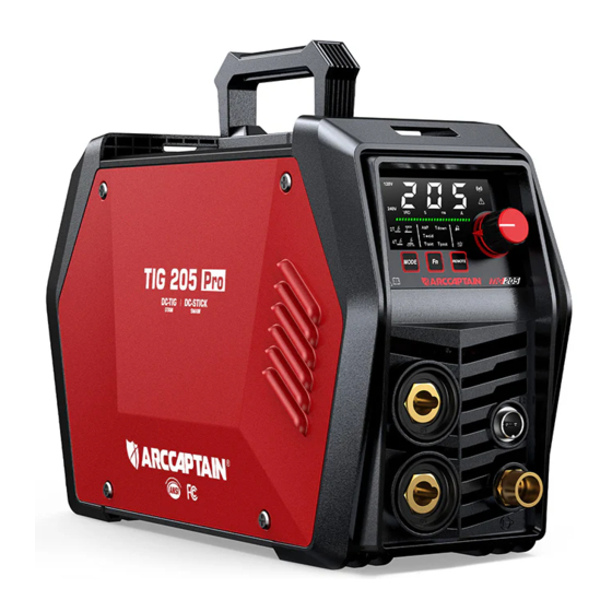
Page 8: Packge
TIG205 Pro TIG torch & accessories WP-17 (13ft/4m) Electrode Holder 10ft/ 3m Earth clamp 10ft/ 3m Gas hose Gas hose with gas connector Adapter 240V to 120V Strap Tungsten electrode φ1/16", 6"(1.6mm, 150mm) Operator’s manual For TIG205 Pro 2.3 Technical Parameters... - Page 9 Model TECHNICAL PARAMETERS Units TIG 205 Pro Single Phase Rated Input Power Single Phase AC240V AC120V ±15% Rated Input Capacity Rated Input Current TIG:205A/18.2V TIG:145A/15.8V Rated Output Current/Voltage MMA:205A/28.2V MMA:145A/25.8V 240V 120V Rated Duty Circle No-load voltage DC 65 240V 120V Output Current Range TIG: 10-205...
-
Page 10: Nameplate
2.4 Nameplate: On the machine, there is a plate that includes all the operating specifications for your new unit. The serial number of the product is also found on this plate. The duty cycle rating of a welder defines how long the operator can weld and how long the welder must rest and be cooled. - Page 11 Part name Function Picture 1.Digital screen To display the welding information 2.Parameter Rotate knob adjust adjustment knob parameters MMA/DC-TIG 2T/DC-TIG 3.Mode button 4T/Cold-TIG welding mode conversion. For Current/Tweld/Ttakt/Down slope/ 4.Fn button Post Gas conversion. 5.Remote mode Panel/Remote/Foot pedal button conversion. connect Electrode 6.Output“+”...
-
Page 12: Panel Functions Of Tig205Pro
3.2 Panel functions of TIG205Pro Figure 4 Part name Function Parameter Rotate the knob to adjust the parameters. adjustment knob For MMA/2T/4T/Cold-TIG welding mode conversion. Button “ ” For Current/Tweld/Ttakt/Down slope/ Post Gas conversion. Button “ ” For Panel/Remote/Foot pedal conversion. Button “... - Page 13 If the indicator is on, it indicates the DC-TIG 4T Welding mode is selected. If the indicator is on, it indicates the MMA Welding mode is selected. If the indicator is on, it indicates the Cold-TIG Welding mode is selected. This indicates the value of output current.
-
Page 14: Installation And Connection
The machine is on alarm state when it is blinking. The machine is connected to wireless. *For more detailed information about the connection and operational guidelines for the ARCCAPTAIN APP, please visit www.arccaptain.com and explore the resources available there. 4.INSTALLATION AND CONNECTION The following operation requires sufficient professional knowledge on electric aspect and comprehensive safety knowledge. -
Page 15: Tig Welder Cable Connection
Installation space requirements Distance between welder and wall should be more than 20cm(7.87"); distance between two abreast welders should be more than 30cm (11.82") . You may refer to the below suggested reserved installation space to confirm the installation position. Department Front Left Side... - Page 16 4.Gas connection: connect argon tube with welder back panel’s brass mouthpiece tightly. Air supply passage should include argon decompressed flowmeter, gas hose; Be sure to secure the hose connections to avoid poor solder joint protection due to gas leakage or air intrusion. (Figure 7) NOTE: Make sure the link is partially tightened.
-
Page 17: Tig Welder Operation
Assemble tig torch 1. Consult Settings Chart, on top of Welder, to determine proper Tungsten Electrode size to be used with thickness of material to be welded. 2. Match Collet and Collet Body sizes to Tungsten Electrode size. 3. Thread Collet Body into the front of the Torch. - Page 18 Helmet interface on the back of the machine.If you need to buy cold welding helmet, go to http://www.arccaptain.com Hold TIG Torch in one hand and the TIG Rod (sold separately) in other hand. Both hands need to wear protective gloves.
-
Page 19: Tig Welding Mode
Remove Ground Clamp from workpiece or table. Disconnect TIG Torch and Ground Cables. Close gas cylinder’s valve securely, remove regulator and replace cap. Disconnect Gas If Electrode has dulled or been otherwise contaminated, use pliers or a suitable tool to grip the Electrode above the contaminated section and snap off the end of the Electrode. - Page 20 Description Picture 1. Insert the cable plug with electrode holder into the “+” socket on the front panel of the welding machine, and tighten it clockwise. NOTICE: The holder connector MUST be tightly connected to the ocket to avoid power short circuit.Set Electrode Holder down on nonconductive,nonflammable surface away from any...
-
Page 21: Mma Welding Mode
3. Place the bare metal end of the Stick Electrode inside the jaws of the Electrode Holder. NOTICE: Ensure that the clip is on the conductive side of the electrode. Ensure that it is securely clamped. Figure 13 4. When you use Alkaline rods (E7018), need to DCEP, that is connect the holder and ground clamp as mentioned above in... -
Page 22: Input Power Connection
And then turn the Power Switch ON. NOTE: For optimal performance, connect the TIG205 Pro to a 50A branch circuit. If connected to a circuit with lower capacity, expect reduced welding current and duty cycle.The circuit must be equipped over 50A with delayed action-type circuit breaker or fuse. - Page 23 Step 1: Thread the strap through the strap hole in front of the welder. Figure 15 Step 2: Thread the strap through the nylon buckle as shown in the diagram. Figure 16 Step 3: Thread the strap through the strap hole in back of the welder.
-
Page 24: Welding Parameters Table
6. WELDING PARAMETERS TABLE 6.1 Parameters for TIG electrode Electrode diameter Amperage range on DCEN Amperage range on DCEP Straight polarity Straight polarity inch .040" 15-80 1/16" 70-150 10-20 3/32" 150-205 15-30 6.2 Parameters for TIG welding on stainless steel sheet Electrode diameter Plate thickness Welding current(A) - Page 25 Gas flow (L/min) Double Weldi Single V Welding Plate Electrode Nozzle Wire diameter groove current thickness diameter mm diameter Square groove layer mm (inch) with mm (inch) (inch) mm (inch) groove with root root face face 0.5(0.020") 1.5(0.059") 1 (0.040") 30~50 8~10 14~16...
-
Page 26: Cold Tig Parameters Table
20~22 3.0~4.0 8(0.315") 4.0(5/32") 140~180 14~16 12~14 25~28 (0.787"-0.866 (0.118"-5/32") ") 20~22 3.0~4.0 10(0.394") 4.0(5/32") 160~205 14~16 12~14 25~28 (0.787"-0.866 (0.118"-5/32") ") 6.4 Cold TIG Parameters Table Joint Plate Welding Welding Recommen Gas Flow Tungsten Tungsten type thickn current time needle needle tip parameter... -
Page 27: Mma Welding Parameters Table
If the arc diverges or the arc sound becomes louder during the welding process, the tungsten needle should be polished before welding. 6.5 MMA Welding Parameters Table Following table is suitable for mild steel welding. For other materials, consult related materials and welding process for reference. -
Page 28: Tig Characteristics
Nozzle Molten pool Tungsten Filler wire Weld Figure 20 TIG diagram Argon is an inert-gas and does not react chemically with metal, so it will not burn the alloy elements in the metal being welded and can fully protect the metal molten pool from oxidation. Moreover, argon is insoluble in liquid metal at high temperature, so it is not easy to cause gas pores in the weld. -
Page 29: Tig Process
The welding gun nozzle serves as an important component that determines the gas shield protection performance, and the common nozzle shapes are as shown in the figure. The cylindrical nozzle with conical or spherical tail has the best protection effect, as the argon gas flow rate is uniform, which makes it easy to maintain laminar flow. - Page 30 and helium. It is a by-product of fractional distillation of liquid air in an oxygen plant to produce oxygen. In China, bottled argon is used for welding, and its filling pressure is 15MPa at room temperature. The cylinder is painted gray and marked with the word "Argon". The chemical composition requirements of pure argon are: Ar ≥...
-
Page 31: Welding Parameters
Effective protection zone Melting zone Oxidation zone (a) Good protection effect (b) Bad protection effect Figure 22 Argon protection effect diagram In addition, the argon protection effect can be evaluated by directly observing the color of the weld face. Taking welding on stainless steels as an example, if the weld metal surface is silvery white or golden yellow, it means that the protection effect is good;... -
Page 32: General Requirements Of Tig
effect. Usually the flow of argon is in the range of 3-20L/min. Welding speed: Under certain conditions of tungsten electrode diameter, welding current and argon gas flow, too fast welding speed will cause the shielding gas flow to deviate from the tungsten electrode and the molten pool, thereby affecting the argon protection effect. -
Page 33: Tools For Mma
and then clamp the electrode by the electrode holder. When welding, arc is ignited between the electrode and the weldment, and the end of the electrode and part of the weldment are fused to form a weld crater under the high-temperature arc. The weld crater is quickly cooled and condensed to form weld joint which can firmly connect two separate pieces of weldement as a whole. - Page 34 igniting and arc stabilizing conveniently as well as ensure the quality of weld joint. Wire brush can be used for condition with low requirement on dust removal; grinding wheel can be used for condition with high requirement on dust removal. Posture in operating ...
- Page 35 Electrode manipulation The electrode manipulation actually is a resultant movement in which the electrode simultaneously moves in three basic directions: the electrode gradually moves along the welding direction; the electrode gradually moves toward the weld crater; and the electrode transversely swings. (See Figure 26) Electrode should be correctly manipulated in three movement directions after arc is ignited.
-
Page 36: Troubleshooting
a) arc extinguishing at the outside of weld bead b) arc extinguishing on the weld bead Figure 28 Arc extinguishing modes Weldment cleaning Clean welding slag and spatter with wire brush, etc after welding. 9. TROUBLESHOOTING The following operation requires sufficient professional knowledge on electric aspect and comprehensive safety knowledge. - Page 37 1.Might be over-current protection; please turn off the machine; restart the machine when abnormity indicator stop lighting, and Fan is working; abnormity indicator welder will go back to normal operation; lights, but with no welding output; 2.Might be over-heat protection; waif for 5-7 minutes and machine will go back to normal operation automatically;...
-
Page 38: Maintenance
can be continued after the inner temperature falls into the standard range and the “E60” code is disappeared. 10. MAINTENANCE The following operation requires sufficient professional knowledge on electric aspect and comprehensive safety knowledge. Operators should be holders of valid qualification certificates which can prove their skills and knowledge.
Need help?
Do you have a question about the TIG205 Pro and is the answer not in the manual?
Questions and answers
will 205 tig aluminum