
Related Manuals for ARCCAPTAIN TIG200


Summary of Contents for ARCCAPTAIN TIG200
- Page 1 Digital Welder Expert, Know You More Inverter Welding Machine TIG200 User Manual www.arccaptain.com https://www.arccaptain.com...
- Page 2 Digital Welder Expert, Know You More Dear Valued Customer, Thank you very much for being our valued customer. ARCCAPTAIN welder was built by high quality components, every single unit machine was passed multiple industry leading laboratory tests to provide a great welding experience and performance.
-
Page 3: Table Of Contents
2.4 Composition and Picture of the welding machine system..........6 2.5 System characteristics......................7 3. FUNCTION....................... 8 3.1 Panel of TIG200........................8 3.2 Panel functions of TIG200....................8 4. INSTALLATION AND CONNECTION..............9 4.1 Installation requirements.....................9 4.2 Electrical connection......................11 4.3 Installation and Commission.................... 11 4.4 Strap Installation........................ -
Page 4: Safety Guidance
Ensure there is fire extinguisher nearby, and make sure someone has been trained to operate the fire extinguisher. Do not weld closed container. Do not use this machine for pipe thawing. https://www.arccaptain.com... - Page 5 Make sure the connecting wires inside the machine are correctly connected after replacing the PCBs, and then the machine can be run. Otherwise, there is a risk of damage to property. https://www.arccaptain.com...
-
Page 6: Preparation Before Welding
To avoid gas poisoning, suffocation, dust poisoning, please use air discharge equipment as required and wear respiratory protection devices. Please wear safety goggles or other protection devices which are of sufficient shading when welding or guiding welding. https://www.arccaptain.com... -
Page 7: Precautions For Discard
Built-in MCU technology and IGBT inverter Welder, totally digital control, which ensures great and stable welding performance. TIG200 is TIG and MMA 2 in 1 Multi-Process welding machine. MMA/Stick welding features: hot start, arc force and an-stick. ... -
Page 8: Technical Parameters
Remote control function available: support foot pedal & analog torch (purchase additional if need). 2.2 Technical Parameters Items TIG200 Rated Input Power Single Phase AC220V/AC110V ±15% 50Hz/60Hz Rated Input Capacity ( kVA ) Rated Input Current ( A )... -
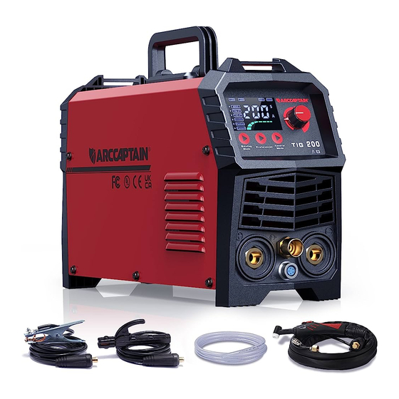
Page 9: Composition And Picture Of The Welding Machine System
Digital Welder Expert, Know You More Pic 1 Welder Appearance and Dimension ( Unit : mm/in ) 2.4 Composition and Picture of the welding machine system 1) Welding system composition Pic 2 Welding System Composition https://www.arccaptain.com... -
Page 10: System Characteristics
200A-16mm ( 9ft/ 3m ) DKJ 35-50 Electrode Holder Earth clamp 300A-16mm ( 9ft/ 3m ) DKJ 35-50 Operator’s manual Operator’s manual of TIG200 Gas hose Gas hose with gas connector Conversion adapter American adapter plug Strap 0.1*4.3ft (30mm*1500mm), Black Tungsten electrode φ... -
Page 11: Function
Digital Welder Expert, Know You More 3. FUNCTION 3.1 Panel of TIG200 Pic 5 Front panel of TIG200 Pic 6 Back panel of TIG200 3.2 Panel functions of TIG200 Part name Function 1.It displays parameters value which is set currently;... -
Page 12: Installation And Connection
Please consult and confirm in advance if there is any special installation requirement. If the Welding power is paced on tilt plane, pay attention to avoid it topple over. The Welding power is forbidden to use thaw pipe. https://www.arccaptain.com... -
Page 13: Electrical Connection
Don’t touch with bare hands. Don’t place heavy items on cables. Water pipe, building metal may not be fully grounded; please don’t use them as safe earth connection. Every welder’s yellow/green cable should be reliably grounded. https://www.arccaptain.com... -
Page 14: Installation And Commission
(See Pic 7.) Pic 7 Installation of TIG torch 3. Connection of TIG torch’s components. ① Torch trigger ② Short/Long Back cap ③ Gasket ④ Collet Body ⑤ Collet ⑥ Ceramic nozzle Pic 8: Connection of TIG torch https://www.arccaptain.com... - Page 15 Please set welding current according to workpiece thickness. Keep the distance between torch tungsten and workpiece at 2-4mm/0.08-0.16in; pull the torch trigger and welder’s HF discharging noise will disappear as long as arc is successfully ignited; welding can be https://www.arccaptain.com...
- Page 16 • The main current drops with the set down-slope time to the end-crater current Iend (minimum current). Step 4 • Release torch trigger 1, the arc extinguishes. • The set gas post-flow time begins. Immediate termination of the welding process in the downslope by releasing torch trigger 1. https://www.arccaptain.com...
- Page 17 • Insert cable plug of the workpiece lead into either the "+" or "-" welding current connection socket and lock by turning to the right. Polarity depends on the instructions from the electrode manufacturer given on the electrode packaging. https://www.arccaptain.com...
-
Page 18: Strap Installation
Step 5: Proper state after installation: 1. Strap does not twist; 2. Buckle side of shoulder pad is up, while its flat side faces the machine (as shown in the picture); 3. Straps are well locked.(See Pic 17) Pic 17 https://www.arccaptain.com... -
Page 19: Welding Parameters Table
200-320 Parameters for TIG welding on stainless steel sheet (for reference only) Electrode diameter mm Plate thickness mm Welding current(A) Gas flow(L/min) (inch) (inch) 1~2mm 1~3mm (0.040”-5/64”) (0.040”- 0.12”) 50~80 80~120 121~160 2~4mm 3~6mm 161~200 (5/64”-5/32 “) (0.12”-0.24”) 201~300 https://www.arccaptain.com... - Page 20 25~28 (0.118"-5/32”) (0.787"-0.866") 3.0~4.0 20~22 10(0.394") 4.0(5/32”) 160~200 14~16 12~14 25~28 (0.118"-5/32”) (0.787"-0.866") 20(0.787") 4.0(5/32”) 4(5/32”) 200~240 12~14 10~12 18(0.708") 4.0~5.0 22(0.866") 4.0(5/32”) 230~250 15~18 18~20 18~20 20(0.787") (5/32”-0.197") 3.0~4.0 25(0.984") 15~16 4.0(5/32”) 200~220 16~18 20~26 26~30 22(0.866") (0.118"-5/32”) https://www.arccaptain.com...
-
Page 21: Maintenance
Whether the machine enclosure has color fading or overheating problems; abnormal, check Whether the fan sounds normal when the machine is Routine interior of the machine. running; Whether there is abnormal smell, abnormal vibration or noise when the machine is running. https://www.arccaptain.com... - Page 22 Make sure the power plug of the machine is pulled out before uncovering the welding machine. When the machine is powered on, keep hands, hair and tools away from the moving parts such as cooling fan, to avoid personal injury or machine damage. https://www.arccaptain.com...
- Page 23 Generally, periodic check should be carried out every 6 months, and it should be carried out every 3 months if the welding environment is dusty or with heavy oily smoke. Beware of corrosion Please clean the plastic parts with neutral detergent. https://www.arccaptain.com...
-
Page 24: Failure Diagnosis And Troubleshooting
Fan doesn’t work and there is no current output 1. front panel potentiometer is not working. Fan works; but output current is not 2. electrolytic capacitor is failed.( replace a capacitance). stable or can’t be controlled by potentiometer; 3. Poor connection. https://www.arccaptain.com... - Page 25 Poor protection for welding bead in temperature welding bead. the end of welding processing. 2. Prolong post-flow time. 1.Change a new tungsten; 2.Remove tungsten oxidation layer. Hard to achieve successful arc ignition; frequent current interruption. 3.Prolong post-flow time; 4.Adjust tungsten electrode discharge distance(around0.8mm) https://www.arccaptain.com...
- Page 26 2.Check if flat cable between front PCB and top PCB is well Display indicates E10 connected. 3.If it is not fixed, the circuit fails. Please contact your distributor. 1.The thermistor is not well connected to control board. Display indicates E61 2.The thermistor is damaged. Please replace it. https://www.arccaptain.com...
- Page 27 Digital Welder Expert, Know You More https://www.arccaptain.com...
Need help?
Do you have a question about the TIG200 and is the answer not in the manual?
Questions and answers