
Related Manuals for Kontron KBox E-430-TGL


Summary of Contents for Kontron KBox E-430-TGL
- Page 1 USER GUIDE KBox E-430-TGL Doc. User Guide, Rev. 1.2 Doc. ID: [To be Determined] www.kontron.com...
- Page 2 KBox E-430-TGL - User Guide, Rev. 1.2 This page has been intentionally left blank www.kontron.com // 2...
- Page 3 In cases of doubt, please contact Kontron. This user guide is protected by copyright. All rights are reserved by Kontron. No part of this document may be reproduced, transmitted, transcribed, stored in a retrieval system, or translated into any language or computer language, in any form or by any means (electronic, mechanical, photocopying, recording, or otherwise), without the express written permission of Kontron.
- Page 4 ENVIRONMENTAL DAMAGE (COLLECTIVELY, "HIGH RISK APPLICATIONS"). You understand and agree that your use of Kontron devices as a component in High Risk Applications is entirely at your risk. To minimize the risks associated with your products and applications, you should provide adequate design and operating safeguards.
- Page 5 If you have any difficulties using this user guide, discover an error, or just want to provide some feedback, contact Kontron support. Detail any errors you find. We will correct the errors or problems as soon as possible and post the revised user guide on our website.
-
Page 6: Symbols
KBox E-430-TGL - User Guide, Rev. 1.2 Symbols The following symbols may be used in this user guide DANGER indicates a hazardous situation which, if not avoided, will result in death or serious injury. WARNING indicates a hazardous situation which, if not avoided, could result in death or serious injury. -
Page 7: For Your Safety
Therefore, in the interest of your own safety and of the correct operation of your new Kontron product, you are requested to conform with the following guidelines. -
Page 8: Lithium Battery Precautions
General Instructions on Usage In order to maintain Kontron’s product warranty, this product must not be altered or modified in any way. Changes or modifications to the product, that are not explicitly approved by Kontron and described in this user guide or received from Kontron Support as a special handling instruction, will void your warranty. -
Page 9: Table Of Contents
KBox E-430-TGL - User Guide, Rev. 1.2 Table of Contents Symbols ..........................................6 For Your Safety ........................................7 High Voltage Safety Instructions .................................. 7 Special Handling and Unpacking Instruction ............................7 Lithium Battery Precautions ..................................8 General Instructions on Usage ..................................8 Quality and Environmental Management .............................. - Page 10 KBox E-430-TGL - User Guide, Rev. 1.2 4.3.4. M.2 Key E Socket ....................................27 4.3.5. M.2 Key M Socket ....................................27 4.3.6. Micro SIM Card Holder..................................28 4.3.7. M.2 Key B Selection Jumper ................................28 Accessing Internal Components ..............................29 5.1.
-
Page 11: List Of Tables
Figure 22: Unscrew the rear panel ................................44 Figure 23: Securing the vertical wall mount plate ..........................44 Figure 24: Securing the KBox E-430-TGL onto the mounting surface vertically ............... 44 Figure 25: Optional horizontal wall mounting kit ..........................45 Figure 26: Keyhole pattern of the horizontal wall mount brackets .................... - Page 12 Figure 31: Hole pattern of the base mounting kit ..........................48 Figure 32: Securing the base mounting bracket ............................ 48 Figure 33: Securing the hooked mounting bracket onto the KBox E-430-TGL ................49 Figure 34: Securing the KBox E-430-TGL onto the mounting surface ..................49 Figure 35: Terminal block plug connector (5.08 mm pitch, for model with front I/O panel Configuration 1) ....
-
Page 13: 1/ General Safety Instructions For It Equipment
Kontron is exempt from accident liability, this also applies during the warranty period. The product has been built and tested according to the basic safety requirements for low voltage (LVD) applications and has left the manufacturer in safety-related, flawless condition. - Page 14 KBox E-430-TGL - User Guide, Rev. 1.2 Additional safety instructions for DC power supply circuits To guarantee safe operation of devices with DC power supply voltages larger than 60 volts DC or a power consumption larger than 240 VA, please observe that: the device is set up, installed and operated in a room or enclosure marked with ‘‘RESTRICTED ACCESS’’, if...
-
Page 15: Electrostatic Discharge (Esd)
KBox E-430-TGL - User Guide, Rev. 1.2 1.1. Electrostatic Discharge (ESD) A sudden discharge of electrostatic electricity can destroy static-sensitive devices or micro-circuitry. Therefore proper packaging and grounding techniques are necessary precautions to prevent damage. Always take the following precautions: 1. - Page 16 KBox E-430-TGL - User Guide, Rev. 1.2 Do not dispose of lithium batteries in general trash collection. Dispose of the battery according to the local regulations dealing with the disposal of these special materials, (e.g. to the collecting points for dispose of batteries).
-
Page 17: 2/ Electromagnetic Compatibility
Consult the dealer or an experienced radio/TV technician for help. Kontron is not responsible for any radio television interference caused by unauthorized modifications of this equipment or the substitution or attachment of connecting cables and equipment other than those specified by Kontron. -
Page 18: 3/ Shipment And Unpacking
6. If you notice any shipping damage or inconsistencies between the contents and your order, please contact Kontron for help and information. 3.2. Scope of Delivery 3.2.1. Standard 1x KBox E-430-TGL (corresponding to the ordered system configuration) 1x power terminal block plug connector (attached on the system in case of not ordering power adapter) ... -
Page 19: 4/ System Overview
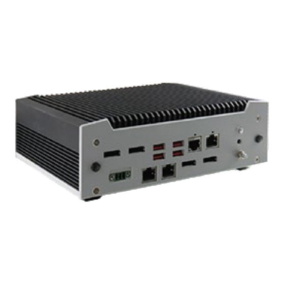
KBox E-430-TGL - User Guide, Rev. 1.2 4/ System Overview The KBox E-430-TGL is a fanless system enclosed within a robust compact aluminum chassis with cooling fins, offering the superior qualities for operation in harsh environments. It can be optionally factory-equipped with an M.2 Key B WWAN and /or M.2 Key E WLAN / Bluetooth card for two antennas. -
Page 20: System Expansion Capabilities
4.1.1. System Expansion via SATA Interface The baseboard comes with an onboard SATA 3.0 interface connector and a corresponding power connector. Users can expand the KBox E-430-TGL with a 2.5" SATA HDD / SSD drive. 4.1.2. System Expansion via M.2 Card Interface The baseboard comes with three onboard M.2 interface connectors with Key B Type 2242 / 3042 / 2280, Key E Type... -
Page 21: Front I/O Panel
KBox E-430-TGL - User Guide, Rev. 1.2 4.2. Front I/O Panel Figure 1: Front I/O Panel (Configuration 1) Figure 2: Front I/O Panel (Configuration 2) 1 DC-In (see Chapter 4.2.1) 2 DC-In (see Chapter 4.2.1) 3 Power Button (See Chapter 4.2.2) 4 Power LED (see Chapter 4.2.3) -
Page 22: Dc-In (3-Pin Terminal Block Socket Connector)
AC power to DC for use with this socket connector. In case you order a power adapter from Kontron, the supplied terminal block plug connector is attached to the power adapter by default. Otherwise, it is attached to the system in this socket connector. -
Page 23: Storage Led
I/O panel. An external (digital) display can be connected to each of thess DP connectors. 4.2.6. 2.5 GbE LAN Depending on the I/O configuration, the KBox E-430-TGL provides either one or three 2.5 GbE LAN ports on the front I/O panel. These connectors are 2.5 Gigabit Ethernet 10/100/1000/2500 Mbit/s, IEEE 1588 capable interfaces. The connectors are standard 8-pin RJ45 type connectors with status LEDs: Figure 3: 2.5 Gigabit Ethernet LED Status... -
Page 24: Usb 3.2 Gen 2
4.2.8. USB 3.2 Gen 2 The KBox E-430-TGL provides four USB 3.2 Gen 2 interfaces on the front I/O panel. These connectors are backward compatible with USB 3.2 Gen 1 / USB 2.0 and allow connection of USB-compatible devices to the system. -
Page 25: Internal View
KBox E-430-TGL - User Guide, Rev. 1.2 4.3. Internal View Figure 5: Internal View (without cover, model with front I/O Configuration 1) Figure 6: Internal View (without cover, model with front I/O Configuration 2) www.kontron.com // 25... -
Page 26: Figure 7: Internal View (Bottom Side Of The Baseboard)
KBox E-430-TGL - User Guide, Rev. 1.2 1 DDR4 SO-DIMM Memory Socket (DIMM1 & DIMM2, see Chapter 4.3.1) 2 SATA Data Connector (CN27, see Chapter 4.3.2) 3 SATA Power Output Wafer (CN9, see Chapter 4.3.2) 4 M.2 Key B Socket (M2B1, see Chapter 4.3.3) 5 M.2 Key E Socket (M2E1, see Chapter 4.3.4) -
Page 27: Ddr4 So-Dimm Memory Socket
4.3.3. M.2 Key B Socket The KBox E-430-TGL reserves a M.2 Key B socket (Figure 5 & 6, pos. 4) with the support of PCIe x1 / SATA 3.0, USB 2.0 and UIM interfaces, allowing the expansion with a Type 22x42 / 30x42 / 22x80 M.2 WWAN module or M.2 SSD drive. -
Page 28: Micro Sim Card Holder
4.3.6. Micro SIM Card Holder The baseboard of the KBox E-430-TGL is equipped with a Micro SIM card holder to accommodate a Micro SIM card for WWAN service access. It is connected to UIM signals on the M.2 Key B socket. -
Page 29: 5/ Accessing Internal Components
KBox E-430-TGL - User Guide, Rev. 1.2 5/ Accessing Internal Components This section contains important information that you must read before accessing the internal components. You must follow these procedures properly when installing, removing or handling any board. It is recommended to expand your system with applicable expansion card(s) before it is installed into an equipment, machine or cabinet. -
Page 30: Opening And Closing The Chassis
Disconnect all peripherals. 2. The KBox E-430-TGL should lay on a flat, clean surface with the access cover facing upwards. 3. Loosen and remove the Phillips screws (two located on the front I/O panel, two on the rear I/O panel and the other four on the bottom), that secure the access cover to the chassis. -
Page 31: Figure 11: Unscrewing The Access Cover (Model With Front I/O Configuration 2)
KBox E-430-TGL - User Guide, Rev. 1.2 Figure 11: Unscrewing the access cover (model with front I/O Configuration 2) 4. Lift the access cover up. 5. Now you have access to the internal DDR4 SO-DIMM (for the model with front I/O Configuration 1), M.2 Key B, M.2 Key E and Micro SIM Card slots / sockets respectively in order to remove or install hardware components. -
Page 32: Figure 12: Unscrewing The Daughter Board (Model With Front I/O Configuration 2)
KBox E-430-TGL - User Guide, Rev. 1.2 Figure 12: Unscrewing the daughter board (model with front I/O Configuration 2) 7. Lift the daughter board up. 8. Now you have access to the internal DDR4 SO-DIMM sockets (for the model with front I/O Configuration 2) in order to remove or install memory modules. -
Page 33: Installing So-Dimm Memory Module(S)
14. For closing replace carefully the access cover to the system and screw it on with the retained screws. Tighten the retained screws when the cover is firmly in place. When used as intended, the KBox E-430-TGL is to operate only in closed condition. Only when the access cover is properly fixed with the screws and the front side with... -
Page 34: Installing A M.2 Key B Ssd / Expansion Card
KBox E-430-TGL - User Guide, Rev. 1.2 Use memory modules with the same memory density in both socket! In case only one memory module is installed, we suggest installing it on the socket DIMM1. 7. In order to close the device, proceed step 14 for model with front I/O Configuration 1 or step 13 - - 14 for model with front I/O Configuration 2 described in the subsection 5.1 "Opening and Closing the Chassis". -
Page 35: Installing A Micro Sim Card
6. After closing the cover, lock the cover by sliding the closed cover in the direction shown in Figure 15. Figure 15: Installing the Micro SIM card 7. In order to close the KBox E-430-TGL, proceed step 14 described in the subsection 5.1 "Opening and Closing the Chassis". -
Page 36: 6/ Thermal Considerations
The applied cooling method provides adequate cooling of the device during operation and performs a one-way thermal transfer to the chassis. Three sides of the KBox E-430-TGL consist of a compact aluminum U-shaped chassis are with cooling fins. The cooling fins provide heat dissipation during operation. - Page 37 KBox E-430-TGL - User Guide, Rev. 1.2 When the KBox E-430-TGL is extended and configured with third party components like M.2 expansion card(s) and hard drives (HDD or SSD), it has to be taken into account that the air temperature inside the system is higher than the ambient temperature.
-
Page 38: 7/ Installation Instructions
Refer also to section 10.1.2 ‘‘Mechanical Specifications’’. The KBox E-430-TGL must be firmly attached to a clean flat and solid mounting surface. Use proper fastening materials suitable for the mounting surface. Ensure that the mounting surface type and the used mounting solution safely support the load of the KBox E-430-TGL and the attached components. - Page 39 KBox E-430-TGL - User Guide, Rev. 1.2 www.kontron.com // 39...
-
Page 40: System Mounting
I/O panel Configuration 1 as the example. They are applicable to the model with front I/O panel Configuration 2. 7.1.1. DIN Rail Mounting Depending on the ordered KBox E-430-TGL configuration, your system may be supplied with a DIN rail mounting kit (Figure 16). Figure 16: Optional DIN rail mounting kit... -
Page 41: Figure 17: Securing The Adapter Plate
7 Screw Hole for securing adapter plate to KBox E-430-TGL To mount the KBox E-430-TGL please proceed according to the steps described: 1. Secure the adapter plate on the rear or bottom side of the chassis in a horizontal or vertical direction with the supplied screws (M3 x 4 mm) depending on usage requiremets, application scenarios and / or surrounding conditions. -
Page 42: Figure 18: Securing The Din Rail Clamp
4. Clip the top of the DIN rail clamp into the DIN rail and push the bottom of the DIN rail clamp firmly until it clamps onto the bottom of the DIN rail. Figure 19: Clamping the KBox E-430-TGL onto the DIN rail From rear side in vertical direction From rear side in horizontal direction ... -
Page 43: Vertical Wall Mounting
3 Screw Hole for Securing the Vertical Wall Mount Plate to the Chassis of the KBox E-430-TGL To mount the KBox E-430-TGL with the sipplied vertical wall mount plate, the control cabinet / custom enclosure / machine / monitor / wall must have the screw pattern shown as Figure 21 for mounting. -
Page 44: Figure 22: Unscrew The Rear Panel
Leave approximately 2 mm of clearance between the back of the screw head and the mounting surface. 5. Place the KBox E-430-TGL onto the mounting surface by placing the wide portion of each keyhole slot over the corresponding screw on the mounting surface. -
Page 45: Horizontal Wall Mounting
3 Keyhole Slot for Hanging the KBox E-430-TGL with a Screw 4 Screw Hole for Securing the Horizontal Wall Mount Bracket to the Chassis of the KBox E-430-TGL To mount the KBox E-430-TGL with the supplied horizontal wall mount brackets, the control cabinet / custom enclosure / machine / monitor / wall must have the screw pattern shown as Figure 26 for mounting. -
Page 46: Figure 27: Removing The Screws
Leave approximately 2 mm of clearance between the back of the screw head and the mounting surface. 5. Place the KBox E-430-TGL onto the mounting surface by placing the wide portion of each keyhole slot over the corresponding screw on the mounting surface. -
Page 47: Vesa Mounting
(Figure 30). The kit consists of two parts: a base bracket (Figure 30, pos. 1) to be fixed permanently on the mounting surface and another hooked bracket (Figure 30, pos. 2) to hold the KBox E-430-TGL with a hand-screw knob (Figure 30, pos. -
Page 48: Figure 31: Hole Pattern Of The Base Mounting Kit
Figure 32: Securing the base mounting bracket 3. Secure the hooked mounting bracket onto the bottom side of the KBox E-430-TGL (Figure 33) with M3 screws (6 mm long) via the VESA 75 mounting holes. The orientation depends on usage requirements, application scenarios and / or surrounding conditions. -
Page 49: Figure 33: Securing The Hooked Mounting Bracket Onto The Kbox E-430-Tgl
/ scenarios / conditions. conditions. 4. Place the KBox E-430-TGL onto the mounting surface by sliding the hooked mounting bracket into the based mounting bracket (Figure 34). 5. Secure the hand-screw knob located on the hooked mounting bracket to fix two brackets (Figure 34). -
Page 50: Dc Power Connection
7.2. DC Power Connection Depending on the ordered configuration, the KBox E-430-TGL is connected by either a 3-pin 5.08 mm pitch terminal block socket connector (Figure 1, pos. 1) or 3-pin 3.5 mm pitch terminal block socket connector (Figure 2, pos. 2) via a DC power supply wiring to a DC power source. -
Page 51: Cabling
5 Location for inserting the positive (+) input wire In case of ordering a power adapter as well as a power cord from Kontron, the 3-pin terminal block plug connector (Figure 35 or 36) should be well attached to the power adapter. For DC power connection, users can use the power cord and power adapter to carry AC power from AC power source and then convert it into DC 24 V. -
Page 52: 8/ Start Up
The DC-In terminal block socket connector (Figure 1, pos. 1 or Figure 2, pos. 2) is located on the front side of the KBox E-430-TGL. The KBox E-430-TGL will be connected to a DC main power supply via the supplied terminal block plug connector (Figure 35 or 36) and corresponding power wires (prepared as described in the subsection 7.2.1 "Cabling"),... - Page 53 3. Connect the terminal block plug connector prepared as described in the subsection 7.2.1 "Cabling" to the DC-In terminal block socket connector (Figure 1, pos. 1 or Figure 2, pos. 2) of the KBox E-430-TGL. The DC input connector is located on the front side.
-
Page 54: Operating System And Hardware Component Drivers
If you have ordered the KBox E-430-TGL without a pre-installed operating system, you will need to install the operating system and the appropriate drivers for the system configuration you have ordered (optional hardware components) yourself. -
Page 55: 9/ Maintenance And Cleaning
9/ Maintenance and Cleaning Equipment from Kontron requires only minimum servicing and maintenance for proper operation. For light soiling, clean the KBox E-430-TGL with a dry cloth. Carefully remove dust from the surface of the chassis using a clean, soft brush. -
Page 56: Technical Specifications
KBox E-430-TGL - User Guide, Rev. 1.2 Technical Specifications Table 3: Technical Specifications Configura t ion 1 Con figura t ion 2 System Processor 11th Generation Intel® Core™ U-Series Processors Intel® Celeron® 6000 Series Processors Memory 2x DDR4 SO-DIMM ... -
Page 57: Mechanical Specifications
KBox E-430-TGL - User Guide, Rev. 1.2 Cooling Method Passive Software OS Support Windows 10, Linux 10.1. Mechanical Specifications Table 4: Mechanical Specifications Construction Aluminum Metal Chassis Dimensions (W x D x H) 205 mm x 126.6 mm x 65.5 mm / 8.07’’ x 4.98’’ x 2.58’’... -
Page 58: Figure 38: Mechanical Drawing (Model With Front I/O Configuration 2)
KBox E-430-TGL - User Guide, Rev. 1.2 Figure 38: Mechanical Drawing (model with front I/O Configuration 2) (unit: mm) www.kontron.com // 58... -
Page 59: Environmental Conditions
KBox E-430-TGL - User Guide, Rev. 1.2 10.2. Environmental Conditions Table 5: Environmental Conditions Operating Temperature 0 °C ~ 50 °C / 32 °F ~ 122 °F Storage Temperature -20 °C ~ 80 °C / -4 °F ~ 176 °F ... -
Page 60: 11/ Standard Interfaces
KBox E-430-TGL - User Guide, Rev. 1.2 11/ Standard Interfaces -- - Pin Assignments Low-active signals are indicated by a minus sign. 11.1. DC Power Input (Configuration 1) Table 7: DC Power Input (see Figure 1, pos. 1) Signal Name 3-pin Terminal Block Socket Connector (5.08 mm pitch) -
Page 61: Gigabit Ethernet Connector
KBox E-430-TGL - User Guide, Rev. 1.2 11.4. Gigabit Ethernet Connector Table 10: Gigabit Ethernet Connector (see Figure 1 & 2, pos. 9) Signal Name RJ45 TX1+ TX1- 1 2 3 4 5 6 7 8 TX2+ TX3+ TX3- TX2-... -
Page 62: Dp Connector
KBox E-430-TGL - User Guide, Rev. 1.2 11.6. DP Connector Table 12: DP Connector (see Figure 1 & 2, pos. 7) Signal Name DP Connector ML_Lane0p ML_Lane0n ML_Lane1p ML_Lane1n ML_Lane2p ML_Lane2n ML_Lane3p ML_Lane3n Config1 Config2 AUX_CHp AUX_CHn Hot_Plug DP_PWR 11.7. RS232/422/485 Serial Port Table 13: RS232/422/485 Serial Port (see Figure 1 &... -
Page 63: 12/ Bios
Supervisor Password (see Security menu), press <RETURN>, and proceed with step 5. 5. A setup menu will appear. The KBox E-430-TGL uEFI BIOS setup program uses a hot key-based navigation system. A hot key legend bar is located on the bottom of the setup screens. -
Page 64: Starting The Uefi Bios
KBox E-430-TGL - User Guide, Rev. 1.2 12.2. Starting the uEFI BIOS The Setup utility features shows six menus in the selection bar at the top of the screen: Main Advanced Power Boot Security Save & Exit ... -
Page 65: Figure 39: Bios Main Menu Screen System Data And Time
KBox E-430-TGL - User Guide, Rev. 1.2 Figure 39: BIOS Main Menu Screen System Data and Time Aptio Setup - AMI Main Advanced Power Boot Security Save & Exit Product Information Product Name KBox E-430-TGL-GPA BIOS Version KBXGV430.R002 (x64) BIOS Build Date... -
Page 66: Advanced Setup Menu
KBox E-430-TGL - User Guide, Rev. 1.2 12.2.2. Advanced Setup Menu The Advanced setup menu provides sub-screens and functions for advanced configurations. The following sub- screen functions are included in the menu: LAN & Audio Configuration Display Configuration ... -
Page 67: Figure 40: Bios Advanced Menu
KBox E-430-TGL - User Guide, Rev. 1.2 Figure 40: BIOS Advanced Menu Aptio Setup - AMI Main Advanced Power Boot Security Save & Exit HD Audio [Enabled] Onboard LAN1 Controller [Enabled] Onboard LAN2 Controller [Enabled] Load Intel I225 UNDI* [Disabled]... -
Page 68: Figure 41: Bios Advanced Menu - Display Configuration
KBox E-430-TGL - User Guide, Rev. 1.2 Figure 41: BIOS Advanced Menu - Display Configuration Aptio Setup - AMI Main Advanced Power Boot Security Save & Exit Display Configuration Aperture Size [256MB] → ←: Select Screen DVMT Pre-Allocated [64M] ↑ ↓: Select Item... -
Page 69: Figure 42: Bios Advanced Menu - - Nvme Configuration
KBox E-430-TGL - User Guide, Rev. 1.2 Figure 42: BIOS Advanced Menu -- - NVMe Configuration Aptio Setup - AMI Main Advanced Power Boot Security Save & Exit NVMe Configuration > TS128GMTE550T → ←: Select Screen ↑ ↓: Select Item Enter: Select +/-: Change Opt. -
Page 70: Figure 44: Bios Advanced Menu - - Sata Configuration
KBox E-430-TGL - User Guide, Rev. 1.2 Figure 44: BIOS Advanced Menu -- - SATA Configuration Aptio Setup - AMI Main Advanced Power Boot Security Save & Exit SATA Configuration SATA Controller(s) [Enabled] → ←: Select Screen ↑ ↓: Select Item... -
Page 71: Figure 45: Bios Advanced Menu - - Usb Configuration
KBox E-430-TGL - User Guide, Rev. 1.2 Figure 45: BIOS Advanced Menu -- - USB Configuration Aptio Setup - AMI Main Advanced Power Boot Security Save & Exit USB Configuration USB Devices: → ←: Select Screen 1 Keyboard ↑ ↓: Select Item... -
Page 72: Figure 46: Bios Advanced Menu - - Amt Configuration
KBox E-430-TGL - User Guide, Rev. 1.2 Figure 46: BIOS Advanced Menu -- - AMT Configuration* * This sub-menu is available only for the model with vPro support. Aptio Setup - AMI Main Advanced Power Boot Security Save & Exit... -
Page 73: Figure 47: Bios Advanced Menu - - Trusted Computing
KBox E-430-TGL - User Guide, Rev. 1.2 Figure 47: BIOS Advanced Menu -- - Trusted Computing Aptio Setup - AMI Main Advanced Power Boot Security Save & Exit Configuration Security Device Support [Disable] Disable Block Sid [Disabled] → ←: Select Screen NO Security Device Found ↑... -
Page 74: Figure 48: Bios Advanced Menu - - Network Stack
KBox E-430-TGL - User Guide, Rev. 1.2 Figure 48: BIOS Advanced Menu -- - Network Stack Aptio Setup - AMI Main Advanced Power Boot Security Save & Exit Network Stack [Disabled] IPv4 PXE Support* [Disabled] IPv6 PXE Support* [Disabled] → ←: Select Screen ↑... -
Page 75: Figure 49: Bios Advanced Menu - - Super Io Configuration
KBox E-430-TGL - User Guide, Rev. 1.2 Figure 49: BIOS Advanced Menu -- - Super IO Configuration* * This sub-menu is available only for the model with front I/O Configuration 1. Aptio Setup - AMI Main Advanced Power Boot Security Save &... -
Page 76: Figure 50: Bios Advanced Menu - - Super Io Configuration - - Serial Port 1 Configuration
KBox E-430-TGL - User Guide, Rev. 1.2 Figure 50: BIOS Advanced Menu -- - Super IO Configuration -- - Serial Port 1 Configuration* * This sub-menu is available only for the model with front I/O Configuration 1. Aptio Setup - AMI... -
Page 77: Figure 51: Bios Advanced Menu - - Super Io Configuration - - Serial Port 2 Configuration
KBox E-430-TGL - User Guide, Rev. 1.2 Figure 51: BIOS Advanced Menu -- - Super IO Configuration -- - Serial Port 2 Configuration* * This sub-menu is available only for the model with front I/O Configuration 1. Aptio Setup - AMI... -
Page 78: Figure 52: Bios Advanced Menu - - H/W Monitor
KBox E-430-TGL - User Guide, Rev. 1.2 Figure 52: BIOS Advanced Menu -- - H/W Monitor Aptio Setup - AMI Main Advanced Power Boot Security Save & Exit PC Health Status CPU Temperature - PECI : +91 C → ←: Select Screen... -
Page 79: Power Setup Menu
KBox E-430-TGL - User Guide, Rev. 1.2 12.2.3. Power Setup Menu The Power setup menu provides functions and a sub-screen for power configurations. The following sub-screen function is included in the menu: WatchDog Timer Configuration Figure 53: BIOS Power Setup Menu... -
Page 80: Figure 54: Bios Power Setup Menu - - Watchdog Timer Configuration
KBox E-430-TGL - User Guide, Rev. 1.2 Feature Option Description ResumeLAN I210 [Disabled], Select whether to enable Wake from LAN Device Intel I210. [OS-Driver], [PW-MagicPacket] Resume By PCI-E [Disabled], Select whether to enable Wake from PCI-E Device. Device [Enabled] Resume By Ring [Disabled], Select whether to enable Wake from Ring Device. -
Page 81: Boot Setup Menu
KBox E-430-TGL - User Guide, Rev. 1.2 12.2.4. Boot Setup Menu The boot setup menu lists the for boot device priority order, that is generated dynamically. Figure 55: BIOS Boot Setup Menu Aptio Setup - AMI Main Advanced Power Boot Security Save &... -
Page 82: Security Setup Menu
The Security setup menu provides information about the passwords and functions for specifying the security settings. The passwords are case-sensitive. The KBox E-430-TGL provides no factory-set passwords. If there is already a password installed, the system asks for this first. To clear a password, simply enter nothing and acknowledge by pressing <RETURN>. -
Page 83: Figure 57: Bios Security Setup Menu - - Secure Boot
KBox E-430-TGL - User Guide, Rev. 1.2 Figure 57: BIOS Security Setup Menu -- - Secure Boot Aptio Setup - AMI Main Advanced Power Boot Security Save & Exit System Mode Setup Secure Boot [Disabled] → ←: Select Screen Not Active ↑... -
Page 84: Figure 58: Bios Security Setup Menu - - Secure Boot - - Key Management
KBox E-430-TGL - User Guide, Rev. 1.2 Figure 58: BIOS Security Setup Menu -- - Secure Boot -- - Key Management Aptio Setup - AMI Main Advanced Power Boot Security Save & Exit Vendor Keys Valid Factory Key Provision [Disabled] >... - Page 85 KBox E-430-TGL - User Guide, Rev. 1.2 Feature Option Description (c) EFI_CERT_RSA2048 (bin) Key Exchange Keys [Details], (d) EFI_CERT_SHAXXX [Export], 2. Authenticated UEFI Variable [Update], 3. EFI PE / COFF Image (SHA256) [Append], Key Source: Factory, External, Mixed [Delete] Authorized...
- Page 86 KBox E-430-TGL - User Guide, Rev. 1.2 12.2.5.1. Remember the password It is highly recommended to keep a record of all passwords in a safe place. Forgotten passwords results in being locked out of the system. If the system cannot be booted because the User Password or the Supervisor Password are not know, contact Kontron Support for further assistance.
-
Page 87: Save & Exit Setup Menu
KBox E-430-TGL - User Guide, Rev. 1.2 12.2.6. Save & Exit Setup Menu The exit setup menu provides functions for handling changes made to the UEFI BIOS settings and the exiting of the setup program. Figure 59: BIOS Save & Exit Setup Menu... -
Page 88: Appendix A: List Of Acronyms
KBox E-430-TGL - User Guide, Rev. 1.2 Appendix A: List of Acronyms The following table does not contain the complete acronyms used in signal names, signal type definitions or similar. A description of the signals is included in the I/O Connector and Internal connector chapters within this user guide. -
Page 89: About Kontron
KBox E-430-TGL - - User Guide, Rev. 1.2 About Kontron Kontron is a global leader in IoT / Embedded Computing Technology (ECT) and offers individual solutions in the areas of Internet of Things (IoT) and Industry 4.0 through a combined portfolio of hardware, software and services.
Need help?
Do you have a question about the KBox E-430-TGL and is the answer not in the manual?
Questions and answers