
Related Manuals for Kozyard Elizabeth KZLPG1216WH


Summary of Contents for Kozyard Elizabeth KZLPG1216WH
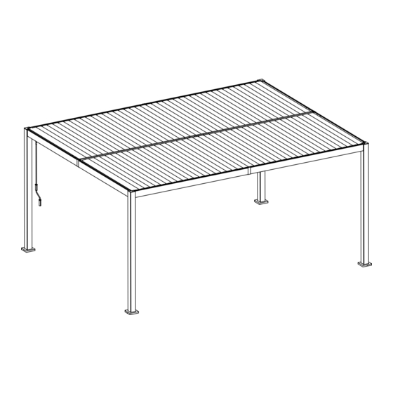
- Page 1 12’x16’ Louver Pergola Assembly Manual Kozyard LLC Products © Copyright 2016 - 2024 Kozyard LLC. | All Rights Reserved.
-
Page 2: Warnings And Cautions
Warnings and Cautions • Please read and follow this assembly and operation guide to reduce personal injury and damage to your pergola. • Do not discard any of the packaging until you have checked that you have all the parts and packs in place , this pergola roof maximum weight capacity is 1700 pounds. - Page 3 DESCRIPTION NAME Part No. Pole L:88.6" Short Beam L:72.4" Short Beam L:72.4" Right Beam L:92.3" Right Beam L:92.3" Left Beam L:92.3" Left Beam L:92.3" Middle Beam L:92.3" Middle Beam L:92.3" Short Lever L:4.3" Long Lever L:64.4" Joint Cover Joint Cover...
- Page 4 Part No. DESCRIPTION NAME Fixed Boards L:69.4" Louver Boards L:69.3" Crank End-Cap Fixture Turbine Fixture Plate Fixture Fixture Gutter Connector Gutter Connector Lever Connector Beam Connector L:20.5"...
- Page 5 Part No. DESCRIPTION NAME Beam Connector L:20.5" Silcone Plate Cover Screws M6*18 Screws M6*15 Screws M6*13 Screws M4*12 104+2 Screws M6*10 Nuts Screws M6*40 Screws M5*12 Tools Tools Tools 10mm...
- Page 6 Step 1: Set up poles (Part A) with stand plates (Part P) and plate cover (Part Y) using screws #1 as shown in diagram. A ×4 Y ×4 #1 ×16 P ×4 M6*18...
- Page 7 Step 2: Connect Beam (Part C8,C81) into one beam using Connector (Part V) with screw #5 as shown in diagram. C8 ×1 V ×1 C81 ×1 #5 ×18 M6*10...
- Page 8 Step 3: Connect Beam (Part D8,D81) into one beam using Connector (Part V) with screw #5 as shown in diagram. D8 ×1 V ×1 D81 ×1 #5 ×18 M6*10...
- Page 9 Step 4: 1. Connect Beams (Part B6,B61) into one beam using Connector (Part V) with screw #5 as shown in diagram. 2. Fix Fixture(Part L) on the middle of Beam Part(B6 ,B61) using screw #2 as shown in diagram. B6 ×2 V ×2 B61 ×2 #2 ×8...
- Page 10 Step 5: Connect Beam (Part M8,M81) into one beam using Connector (Part W) with screw #5 as shown in diagram. M8 ×1 W ×1 M81 ×1 #5 ×24 M6*10...
- Page 11 Step 6: Insert the beam (Part B6,B61) into the slot of Pole (Part A) and tighten the screws as shown in diagram.
- Page 12 Step 7: Inset beam (Part C8,C81) and beam (Part D8,D81) into the slot of pole (Part A) and tighten screws as shown in diagram. Tip: Ladders may be needed from this step to Step 16. Tip: At least three people for this step.
- Page 13 Step 8: Connect End-Cap (Part K) to Beams and Poles (Part A) using screws #1 and #8, as shown in the diagram. K ×4 #1 ×16 M6*18 #8 ×12 M5*12...
- Page 14 Step 9: Place a spacer (Part S), then use Silcone (Part X) to cover the seam. Tips: Spacer (Part S) should be coated with Silcone (Part X) on the back ×4 ×1...
- Page 15 Step 10: Connect Beam (Part M8,M81) with Beam (Part B6,B61) using screw #1 as shown in diagram. #1 ×8 M6*18...
- Page 16 Step 11: 1. Place a spacer(Part T), then use Silcone (Part X) to cover the seam on beam (Part M8,M81). 2. Install the connector (Part U) using #5 screws, and the completely finished beam (Part M8,M81,C8,C81,D8,D81). Tips: Spacer (Part T) should be coated with Silcone (Part X) on the back #5 ×8 T ×2...
- Page 17 Step 12: Combine Fixture long lever (Part E2),Short lever (Part E1),Turbine (Part M), Fixture (Part N) to Long Lever (Part E2),Fixture (Part Q,Part R) into one lever using screw #7 and Nut #6. Attention:This Part N must be Placed facing right. Note:it’s critical that the iron piece must be positioned in the same way.
- Page 18 Step 13: 1. Fix finished Lever bars onto Beam (Part B6,B61) using screw #1 as shown in diagram. 2. Fix finished Lever bars onto Beams using screw #2 as shown in diagram. #2 ×8 #1 ×4 M6*15 M6*18 #6 ×4 #3 ×4 M6*13...
- Page 19 Step 14: Put on Louver Boards (Part H) on the top as shown in diagram. Tip : Please Place Boards H depending on this way in sequence. H ×82...
- Page 20 Step 15: Put on Louver Boards (Part G) on the top using Screw #4 to fix them as shown in diagram. G ×2 #4 ×4 M4*12...
- Page 21 Step 16: Install Joint cover (Part F, F1) to the middle of Beam. F ×1 F1 ×4...
- Page 22 Step 17: Hang on Crank (Part J) on the Beam as shown in diagram. Then crank it to your desired open/close shade to enjoy your time. Important tip : For long-term durability, please open the louver boards before it snows to prevent damage from heavy snowfall.
- Page 23 Kozyard always serves you for parts and replacement even if your warranty expires. Kozyard LLC Warehouse in West: 10808 6th ST, Unit 100,Rancho Cucamonga, CA 91730 Warehouse in East: 100 Ethel Rd W, Piscataway, NJ 08854 © Copyright 2016 - 2024 Kozyard LLC. | All Rights Reserved.
Need help?
Do you have a question about the Elizabeth KZLPG1216WH and is the answer not in the manual?
Questions and answers