
Subscribe to Our Youtube Channel
Related Manuals for Kozyard KZLPG1212


Summary of Contents for Kozyard KZLPG1212
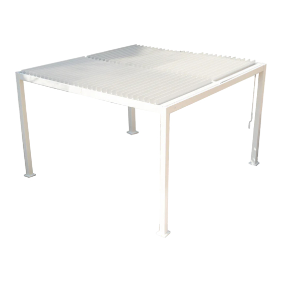
- Page 1 12’x12’ Louver Pergola Assembly Manual Kozyard LLC Products www.kozyard.com © Copyright 2016 - 2023 Kozyard LLC. | All Rights Reserved.
-
Page 2: Warnings And Cautions
Warnings and Cautions Please read and follow this assembly and operation guide to reduce personal injury and damage to your pergola Do not discard any of the packaging until you have checked that you have all the parts pergola 1700 Some parts might have sharp edges/corners.Please follow basic safety precautions t reduce the risk of injures , this item contains small parts which can be swallowed by children. - Page 3 IMAGE NAME Pole Short Beam Short Beam Left Beam Left Beam Right Beam Right Beam Middle Beam Middle Beam Beam Connector 12’x14 Louver Pergola assembly manual page 1...
- Page 4 NAME IMAGE Joint lever Joint Cover Joint Cover Gutter Connector Gutter Connector Lever Connector Louver Boards Louver Boards Crank Long Lever page 2 12’x12’ Louver Pergola assembly manual...
- Page 5 IMAGE IMAGE NAME NAME Short Screws M6*18 Lever Screws Fixture M6*15 Screws Fixture M6*13 Plate Screws M4*12 Cover Plate Screws 104+2 M6*10 Plastic Corner Screws Fixture M6*40 Turbine Screws M8*52 Tools Fixture Tools Silcone 12’x12’ Louver Pergola assembly manual page 3...
- Page 6 Parts Required: N x4 N1 x4 AP x4 Step 1: Set up poles (Part AP) with stand plates (Part N,N1) using screws 1# as shown in diagram. 12’x12’ Louver Pergola assembly manual page 4...
- Page 7 Parts Required: CS6 x2 BS6 x2 T x2 J x2 5# x36 S x1 Connected Beam Overall: Step 2: Connect Beam (Part BS6,CS6) into one beam using Connector (Part T) with screw 5# as shown in diagram.Then use Silcone (Part S) to cover the seam. ①...
- Page 8 Parts Required: 2# x8 Q x2 H x2 Connected Beam Overall: Step 3: Fix Fixture(Part Q) on the middle of Beam Part(BS6 ,CS6) using screw 5# as shown in diagram. ⑤ ⑥ Snap Joint cover (Part H) to the middle of Beam. ⑦...
- Page 9 Parts Required: DL6 x1 ER6 x1 T x1 J x1 J2 x1 S x1 5# x20 Connected Beam Overall: Step 4: Connect Beam (Part ER6,DL6) into one beam using Connector (Part T ) with screw 5# as shown in diagram.Then use Silcone (Part S) to cover the seam. ①...
- Page 10 Parts Required: H x1 S x1 Connected Beam Overall: Step 5: Use Silcone (Part S) to cover the seams around (Part J) in order to avoid leaking. ⑤ ⑥ Snap Joint cover (Part H) to the middle of Beam. ⑦ Compeletly finished Beam (Part ER6,DL6) 12’x12’...
- Page 11 Parts Required: FL6 x1 GR6 x1 T x1 5# x20 S x1 J x1 J2 x1 Connected Beam Overall: Step 6: Connect Beam (Part FL6,GR6) into one beam using Connector (Part T) with screw 5# as shown in diagram.Then use Silcone (Part S) to cover the seam. ②...
- Page 12 Parts Required: H x1 S x1 Connected Beam Overall: Step 7: Use Silcone (Part S) to cover the seams around (Part J) in order to avoid leaking. ⑤ ⑥ Snap Joint cover (Part H) to the middle of Beam. ⑦ Compeletly finished Beam (Part FL6,GR6) 12’x14’...
- Page 13 Parts Required: MR6 x1 ML6 x1 T1 x1 J1 x2 S x1 J2 x2 5# x28 Connected Beam Overall: Step 8: Connect Beam (Part ML6,MR6) into one beam using Connector (Part T1) with screw 5# as shown in diagram.Then use Silcone (Part S) to cover the seam. ②...
- Page 14 Parts Required: H1 x1 S x1 Step 9: Use Silcone (Part S) to cover the seams around (Part J1) in order to avoid leaking. ⑤ ⑥ Snap Joint cover (Part H1) to the middle of Beam. ⑦ Compeletly finished Beam (Part ML6,MR6) 12’x12’...
- Page 15 Parts Required: P x2 8# x6 Step 10: 1. Plug Plastic Corner(Part P) in to Beam (Part DL6,ER6) as shown in diagram. 2.Use Screw 8# to connect Beam and Poles (Part AP) as shown in diagram. Tip: All parts must be put on the carpet in the assembly.
- Page 16 Parts Required: 8# x6 P x2 Step 11: 1. Plug Plastic Corner(Part P) in to Beam (Part FL6,GR6) as shown in diagram. 2.Use Screw 8# to connect Beam and Poles (Part AP) as shown in diagram. Tip: All parts must be put on the carpet in the assembly.
-
Page 17: Parts Required
Parts Required: 8# x6 Step 12: Connect Beam (Part BS6,CS6) with Beam (Part DL6,ER6) and (Part FL6,GR6) as shown in diagram. Tip:Ladders may be needed during this step. Tip: At least three people for this step. 12’x12’ Louver Pergola assembly manual page 15... - Page 18 Parts Required: 8# x6 Step 13: Connect Beam (Part BS6,CS6) with Beam (Part DL6,ER6) and (Part FL6,GR6) as shown in diagram. Tip:Ladders may be needed during this step. 12’x12’ Louver Pergola assembly manual page 16...
- Page 19 Parts Required: 1# x8 Step 14: Connect Beam (Part ML6,MR6) with Beam (Part BS6,CS6) as shown in diagram. Tip:Ladders may be needed during this step. page 17 12’x12’ Louver Pergola assembly manual...
- Page 20 Parts Required: V2 x2 R x2 V x2 7# x4 V1 x2 6# x4 V3 x2 R1 x2 Step 15: Combine Fixture (Part V2),Short lever (Part V1),Turbine (Part R), Fixture (Part R1)to Long Lever (Part V),Fixture (Part V3) into one lever using screw 7# and Nut 6#.
- Page 21 Parts Required: 1# x4 Step 16: Fix finished Lever bars onto Beam (Part BS6,CS6) using screw 1# as shown in diagram. Tip:Ladders may be needed during this step. 12’x12’ Louver Pergola assembly manual page 19...
- Page 22 Parts Required: 6# x4 3# x4 2# x8 Step 17: Fix finished Lever bars onto Beams using screw 2# as shown in diagram. Tip:Ladders may be needed during this step. Attention: The nuts 6# have to be placed outside of steel part. otherwise, nuts will get in the way of manipulation.
- Page 23 Parts Required: 1# x16 Step 18: Lock the top of Poles (Part AP) into Beams using screw 1# as shown in diagram. Tip:Ladders may be needed during this step. 12’x12’ Louver Pergola assembly manual page 21...
- Page 24 Parts Required: K1 x62 Step 19: Put on Louver Boards (Part K1) on the top as shown in diagram Please Place Boards Part K1 depending on this way in sequence. 12’x12’ Louver Pergola assembly manual page 22...
- Page 25 Parts Required: K x2 4# x4 Step 20: Put on Louver Boards (Part K) on the top using Screw 4# to fix them as shown in diagram. page 23 12’x12’ Louver Pergola assembly manual...
- Page 26 Parts Required: L x1 Step 21: Hang on Crank (Part L) on the Beam as shown in diagram. Then crank it to your desired open/close shade to enjoy your time. page 24 12’x12’ Louver Pergola assembly manual...
-
Page 27: Care And Warranty
Care and Warranty Wash frame parts and fabric with mild soap and water,rinse thoroughly. Do not use bleach,acid, or other solvents on the fabric or frame parts. Frame,Bolts,Nuts are warranted to be free from defects in material and workmanship for 1 year from item purchased. - Page 28 Kozyard always serves you for parts and replacement even if your warranty expires. Kozyard LLC Warehouse in West: 10808 6th ST, Unit 100,Rancho Cucamonga, CA 91730 Warehouse in East: 100 Ethel Rd W, Piscataway, NJ 08854 © Copyright 2016 - 2023 Kozyard LLC. | All Rights Reserved.
Need help?
Do you have a question about the KZLPG1212 and is the answer not in the manual?
Questions and answers