Advertisement
Quick Links
Advertisement

Related Manuals for 2VV HRFL3


Summary of Contents for 2VV HRFL3
- Page 1 HRFL3 INSTALLATION MANUAL ver.1 23-09-22...
- Page 2 6. INSTALLATION 7. COMMISSIONING 8. MAINTENANCE 9. SERVICE 10. WIRING DIAGRAM 11. TROUBLESHOOTING 12. LIQUIDATION 13. CONCLUSIONS 2VV. Creating innovative solutions for you and your business since 1995. 2VV. Creating innovative solutions for you and your business since 1995. ver.1 31-08-22...
- Page 3 The assessment was conducted pursuant to harmonized European standards included in the relevant EC Declaration of Conformity. The current and full version of the EC Declaration of Conformity can be found at www.2vv.cz 2VV. Creating innovative solutions for you and your business since 1995.
- Page 4 2 hours, without turning it on, so that its UTP cable 10m inner temperature can match the surroundings. Condensate drain pipes 2VV. Creating innovative solutions for you and your business since 1995. 2VV. Creating innovative solutions for you and your business since 1995. ver.1 31-08-22...
- Page 5 Duct connection - supply air (SUP) Duct connection - diverted air (ETA) Duct connection - exhaust air (EHA) 2VV. Creating innovative solutions for you and your business since 1995. 2VV. Creating innovative solutions for you and your business since 1995. ver.1 31-08-22...
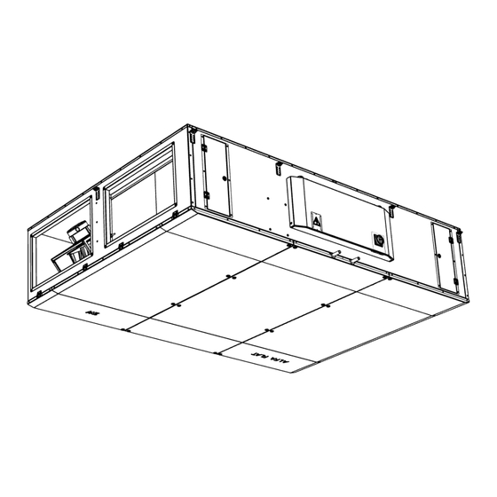
- Page 6 Left version Top view Top view condensation Type ø 3000 2600 2663 1788 1878 1910 2530 1820 2VV. Creating innovative solutions for you and your business since 1995. 2VV. Creating innovative solutions for you and your business since 1995. ver.1 31-08-22...
- Page 7 Air flow [m³/h] HRFL3-300 24,5 11,7 1/2“ 3200 For water temperature gradient 90/70 and inlet air temperature 15°C. 2VV. Creating innovative solutions for you and your business since 1995. 2VV. Creating innovative solutions for you and your business since 1995. ver.1 31-08-22...
- Page 8 3200 For inlet air temperature 27°C with 47% of relative humidity and evaporation temperature 5°C, refrigerant R410A. 2VV. Creating innovative solutions for you and your business since 1995. 2VV. Creating innovative solutions for you and your business since 1995. ver.1 31-08-22...
- Page 9 All the dimensions in the table are in mm tween -20° C ~ +60° C and with a relative humidity of 90%. 2VV. Creating innovative solutions for you and your business since 1995. 2VV. Creating innovative solutions for you and your business since 1995.
- Page 10 Carefully move the device through the door opening to avoid damage. After relocation, install brackets to hang the device from the ceiling. 2VV. Creating innovative solutions for you and your business since 1995. 2VV. Creating innovative solutions for you and your business since 1995. ver.1 31-08-22...
- Page 11 3° to drain the condensate. Top view Type Weight of unit (kg) HRFL3-300-XS0 HRFL3-300-ES0 HRFL3-300-XV1 HRFL3-300-EV1 HRFL3-300-XE1 HRFL3-300-EE1 2VV. Creating innovative solutions for you and your business since 1995. 2VV. Creating innovative solutions for you and your business since 1995. ver.1 31-08-22...
- Page 12 This is an accessory part which must be ordered sepa- rately Circular adaptor to rectangular Type HRFL3-300 All dimensions are in mm 2VV. Creating innovative solutions for you and your business since 1995. 2VV. Creating innovative solutions for you and your business since 1995. ver.1 31-08-22...
- Page 13 If condensation occurs outside the unit, increase the ventilation in the surroun- dings of the unit. 2VV. Creating innovative solutions for you and your business since 1995. 2VV. Creating innovative solutions for you and your business since 1995. ver.1 31-08-22...
- Page 14 When connecting both condensate drain outlets, it is necessary to use two siphons. 2VV. Creating innovative solutions for you and your business since 1995. 2VV. Creating innovative solutions for you and your business since 1995. ver.1 31-08-22...
- Page 15 EXTERNAL POSTHEATER (output - Water= 0-10V, electric=PWM) ВНЕШНИЙ ДООГРЕВ (выход - вода=0-10В, электрический=PWM) EXTERNÍ DOHŘEV (výstup - vodní=0-10V, elektrický=PWM) 2VV. Creating innovative solutions for you and your business since 1995. 2VV. Creating innovative solutions for you and your business since 1995. ver.1 31-08-22...
- Page 16 Condensation pipe MOFL3-300-xC4 83,5 Ø18 External modules DX Type Weight of unit (kg) Condensation pipe MOFL3-300-xD3 Ø18 2VV. Creating innovative solutions for you and your business since 1995. 2VV. Creating innovative solutions for you and your business since 1995. ver.1 31-08-22...
- Page 17 The external module includes sensors, PE grounding conductor and fasteners. The sensors need to be connected according to the diagram given in the section WIRNING DIAGRAM. 2VV. Creating innovative solutions for you and your business since 1995. 2VV. Creating innovative solutions for you and your business since 1995.
- Page 18 WATER IN (PCB “B“, terminals 42, 43) EXT 4 (PCB “B“, terminals 46, 47) WIRING DIAGRAM OF TEMPERATURE SENSORS 2VV. Creating innovative solutions for you and your business since 1995. 2VV. Creating innovative solutions for you and your business since 1995. ver.1 31-08-22...
- Page 19 Secure the droplet eliminator with the screws. Close and screw on the lid. 2VV. Creating innovative solutions for you and your business since 1995. 2VV. Creating innovative solutions for you and your business since 1995.
- Page 20 = number of phases IP = electrical protec- regulator cover. av = Air flow tion Serial number 2VV. Creating innovative solutions for you and your business since 1995. 2VV. Creating innovative solutions for you and your business since 1995. ver.1 31-08-22...
- Page 21 GND DC +12VDC - Accessories Run the power cables through the V-TEC cable gland on the controller. 2VV. Creating innovative solutions for you and your business since 1995. 2VV. Creating innovative solutions for you and your business since 1995. ver.1 31-08-22...
- Page 22 CONTROL PANEL RJ45 plug - Ethernet, Modbus TCP, BACnet Modbus RTU (A-25, B-26, 28 or 66-GND) 2VV. Creating innovative solutions for you and your business since 1995. 2VV. Creating innovative solutions for you and your business since 1995. ver.1 31-08-22...
- Page 23 VÝSTUP REGULACI VÝKONU DOHŘEVU (0-10V nebo PWM) ADIABATICKÝ MODUL (výstup - ON/OFF) ADIABATICKÝ MODUL (výstup - ON/OFF) 2VV. Creating innovative solutions for you and your business since 1995. 2VV. Creating innovative solutions for you and your business since 1995. 0В (вход) ver.1 31-08-22...
- Page 24 (+12V- 27, GND- 28, CANH- 29, CANL- 30) Control panel MODBUS RTU (A-25, B-26, 28 or 66-GND) 2VV. Creating innovative solutions for you and your business since 1995. 2VV. Creating innovative solutions for you and your business since 1995. ver.1 31-08-22...
- Page 25 For details on the power supply, refer to the docu- • cable with three conductors mentation of the given accessory. ● CABLE: cable with three conductors of a cross section min. 0.5 mm . Maximum length 50 m. Not included! 24 V 2VV. Creating innovative solutions for you and your business since 1995. 2VV. Creating innovative solutions for you and your business since 1995. ver.1 31-08-22...
- Page 26 After complete download of these data, the unit is ready for operation. 2VV. Creating innovative solutions for you and your business since 1995. 2VV. Creating innovative solutions for you and your business since 1995.
- Page 27 After removing the screw, press to unlock the cover se- curity system. 2VV. Creating innovative solutions for you and your business since 1995. 2VV. Creating innovative solutions for you and your business since 1995. ver.1 31-08-22...
- Page 28 Use the key supplied with the unit to open the door. • replace filters 2VV. Creating innovative solutions for you and your business since 1995. 2VV. Creating innovative solutions for you and your business since 1995. ver.1 31-08-22...
- Page 29 Reset the safety thermostat RESET 2VV. Creating innovative solutions for you and your business since 1995. 2VV. Creating innovative solutions for you and your business since 1995. ver.1 31-08-22...
- Page 30 The information can be found on the label next to the fuse or directly on the fuse. READ CAREFULLY! When the power supply is resumed after an outage, the unit returns to the status it was before the outage. The unit always remembers its operational status and settings. If you aren’t able to find or remove the cause of the malfunction, or if the repairs require an intervention on the device, contact an authorised service. 2VV. Creating innovative solutions for you and your business since 1995. 2VV. Creating innovative solutions for you and your business since 1995. ver.1 31-08-22...
- Page 31 12 13 14 15 16 17 18 12 13 14 15 16 17 18 I-BUS I-BUS OUTPUT OUTPUT 2VV. Creating innovative solutions for you and your business since 1995. 2VV. Creating innovative solutions for you and your business since 1995. ver.1 31-08-22...
- Page 32 12 13 14 15 16 17 18 12 13 14 15 16 17 18 I-BUS I-BUS OUTPUT OUTPUT 2VV. Creating innovative solutions for you and your business since 1995. 2VV. Creating innovative solutions for you and your business since 1995. ver.1 31-08-22...
- Page 33 12 13 14 15 16 17 18 I-BUS I-BUS OUTPUT OUTPUT Water pump for coil #1 24V GND GND W.PUMP 230V Postheater 2VV. Creating innovative solutions for you and your business since 1995. 2VV. Creating innovative solutions for you and your business since 1995. ver.1 31-08-22...
- Page 34 12 13 14 15 16 17 18 I-BUS I-BUS OUTPUT OUTPUT Water pump for coil #1 24V GND GND W.PUMP 230V Postheater 2VV. Creating innovative solutions for you and your business since 1995. 2VV. Creating innovative solutions for you and your business since 1995. ver.1 31-08-22...
- Page 35 12 13 14 15 16 17 18 I-BUS I-BUS OUTPUT OUTPUT Water pump for coil #1 24V GND GND W.PUMP 230V Postheater 2VV. Creating innovative solutions for you and your business since 1995. 2VV. Creating innovative solutions for you and your business since 1995. ver.1 31-08-22...
- Page 36 In service menu 1616 / 18-HW test open the closing dampers and set up 50% on supply fan, then measure DC voltage signal between terminals 41 and 42 (Supply fan) and check the measured airflow on the HW test screen 2VV. Creating innovative solutions for you and your business since 1995. 2VV. Creating innovative solutions for you and your business since 1995.
- Page 37 Check by measurement the functionality of the safety thermostat with automatic reset and then the functionality of the emergency thermostat 2VV. Creating innovative solutions for you and your business since 1995. 2VV. Creating innovative solutions for you and your business since 1995.
- Page 38 Check the setting of the time schedule modes that there is not selected automatic mode in case the quality sensor is not physi- cally connected. In such case, delete the particular time schedule and set it up again 2VV. Creating innovative solutions for you and your business since 1995. 2VV. Creating innovative solutions for you and your business since 1995.
- Page 39 Check the sensor’s connection to the electronic board – Module A, terminals 45-46 If the connection ok and the fault persists, replace the sensor 2VV. Creating innovative solutions for you and your business since 1995. 2VV. Creating innovative solutions for you and your business since 1995.
- Page 40 Check the sensor’s connection to the electronic board – Module B, terminals 44-45 If the connection ok and the fault persists, replace the sensor 2VV. Creating innovative solutions for you and your business since 1995. 2VV. Creating innovative solutions for you and your business since 1995.
- Page 41 Check the sensor’s connection to the electronic board – Module B, terminals 40-41 If the connection ok and the fault persists, replace the sensor 2VV. Creating innovative solutions for you and your business since 1995. 2VV. Creating innovative solutions for you and your business since 1995.
- Page 42 If the signal LED is flashing on the F module and all pressure sensors are in failure, check the correct connection of the I-BUS cable or functionality of the I-BUS cable itself 2VV. Creating innovative solutions for you and your business since 1995. 2VV. Creating innovative solutions for you and your business since 1995.
- Page 43 If the device is equipped with C module and there is pressor sensor failure on more than one, check the correct addressing on all of the pressure sensors (see correct addressing at Errors 26-31) 2VV. Creating innovative solutions for you and your business since 1995. 2VV. Creating innovative solutions for you and your business since 1995.
- Page 44 If the signal LED is flashing on the G module and the connection is faultless, the module G is faulty and needs to be replaced 2VV. Creating innovative solutions for you and your business since 1995. 2VV. Creating innovative solutions for you and your business since 1995.
- Page 45 If not, the filter calibration must be done (it takes cca 35min.) Start the unit again 2VV. Creating innovative solutions for you and your business since 1995. 2VV. Creating innovative solutions for you and your business since 1995. ver.1 31-08-22...
- Page 46 If the device is equipped with other C modules check the correct addressing on all of the pressure sensors (see correct addressing at Errors 26-27) 2VV. Creating innovative solutions for you and your business since 1995. 2VV. Creating innovative solutions for you and your business since 1995.
- Page 47 The HEPA air filter would need to be replaced soon What to do / check: Order a new HEPA filter and replace it 2VV. Creating innovative solutions for you and your business since 1995. 2VV. Creating innovative solutions for you and your business since 1995. ver.1 31-08-22...
- Page 48 -up anyway, if during this process the return water temperature gets below 15°C the device switches back to “Water heater waiting for hot water” process. 2VV. Creating innovative solutions for you and your business since 1995. 2VV. Creating innovative solutions for you and your business since 1995.
- Page 49 Beware of: When the duct temperature drops below +50°C the heater output is activated for the requested temp. 2VV. Creating innovative solutions for you and your business since 1995. 2VV. Creating innovative solutions for you and your business since 1995.
- Page 50 2VV. Creating innovative solutions for you and your business since 1995. 2VV. Creating innovative solutions for you and your business since 1995.
- Page 52 CONTACT Address 2VV, s.r.o., Nádražní 794, 533 52 Pardubice, Czech Republic Internet: http://www.2vv.cz/...
Need help?
Do you have a question about the HRFL3 and is the answer not in the manual?
Questions and answers