2VV ALFA 95 II vertical Installation And Operation Manual
Hide thumbs
Also See for ALFA 95 II vertical:
- Quick start manual (18 pages) ,
- Installation and operation manual (42 pages)
Table of Contents
Advertisement
Quick Links
Advertisement
Table of Contents

Subscribe to Our Youtube Channel
Related Manuals for 2VV ALFA 95 II vertical


Summary of Contents for 2VV ALFA 95 II vertical
- Page 1 ALFA 95 II v e r t i c a l Installation and operation Manual ver.5 5-05-20...
-
Page 2: Table Of Contents
8.2 CLEANING INTERVALS 9. REMOVING FAULTS 10. SERVICE 10.1 IF THE FAULT PERSISTS 10.2. PUTTING THE UNIT OUT OF OPERATION - DISPOSAL 11. ACCESSORIES 12. WIRING DIAGRAM 13. CONCLUSION 2VV. Creating innovative solutions for you and your business since 1995. ver.5 5-05-20... -
Page 3: Before You Start
Operating instructions. The product´s safety evaluation was based on the harmonized European standards listed in the relevant EC declaration of conformity. The current full version of the EC Declaration of conformity is available at www.2vv.cz 2VV. Creating innovative solutions for you and your business since 1995. -
Page 4: Unpacking
2VV. Creating innovative solutions for you and your business since 1995. ver.5 5-05-20... -
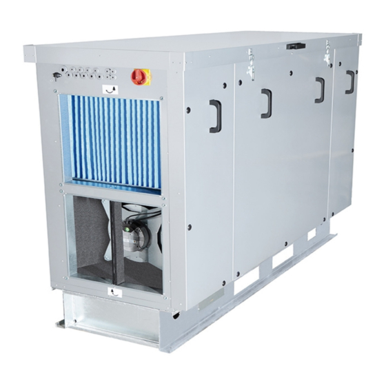
Page 5: Main Components
Shielded cable max. 50 m with a cross. 0.5 mm CABLE NOT INCLUDED Water overflow sensor. Contact On/OFF. Cable length 3 m Main Controls Switch Filter Filter Access for filter maintenance Condensate outlet 2VV. Creating innovative solutions for you and your business since 1995. ver.5 5-05-20... -
Page 6: Dimensions
1128 1095 1894 1128 1095 1500 1894 1128 1095 B-38 B-38 B-38 A-30 A-30 A-30 Type HR95-080 1594 HR95-150 1894 1128 1095 All dimensions are in mm 2VV. Creating innovative solutions for you and your business since 1995. ver.5 5-05-20... - Page 7 B-38 B-38 A-30 A-30 A-30 Type HR95-250 2164 1427 HR95-350 2622 1058 1402 HR95-450 2622 1178 1402 HR95-550 2622 1542 1402 1024 All dimensions are in mm 2VV. Creating innovative solutions for you and your business since 1995. ver.5 5-05-20...
-
Page 8: Technical Parameters
27,9 1/2“ HR95-350..-..-...W 3500 14,1 27,9 1/2“ HR95-450..-..-...W 4500 26,1 1/2“ HR95-550..-..-...W 5500 22,7 27,3 3/4“ * for water 60/40 and the inlet temperature = +15 °C 2VV. Creating innovative solutions for you and your business since 1995. ver.5 5-05-20... - Page 9 HR95-550EC-..-...D 5500 39,41 14,6 90,2 24,2 1 5/8 (1 1/8) Data applies for the inlet temperature = +25°C, 70% RH and the evaporation temperature +5°C, coolant R410A 2VV. Creating innovative solutions for you and your business since 1995. ver.5 5-05-20...
-
Page 10: Installation
Type 1000 HR95-080..-..-..HR95-150..-..-..1000 HR95-250..-..-..1000 HR95-350..-..-..1100 1000 HR95-450..-..-..1300 1200 HR95-550..-..-..1600 1500 All dimensions in the table are in mm 2VV. Creating innovative solutions for you and your business since 1995. ver.5 5-05-20... - Page 11 2VV. Creating innovative solutions for you and your business since 1995. ver.5 5-05-20...
- Page 12 2200 HR95-450..-..-..2200 1005 2565 HR95-550..-..-..1368 2565 1276 2200 all dimensions are in mm * - the total weight of the heaviest unit in the category 2VV. Creating innovative solutions for you and your business since 1995. ver.5 5-05-20...
-
Page 13: Connecting Air Inlets
All connections of the distribution ducts to the ventilation unit must be sealed with a sealant or sealing tape. The minimum distance between ducts or adapters and the unit´s neck is 500 mm. 2VV. Creating innovative solutions for you and your business since 1995. ver.5 5-05-20... -
Page 14: Connecting Mechanical Accessories
Hese accessories must be ordered seperately • 2 actuators (with one or two wires, voltage 230 V) • 8 M8 bolts and nuts • 16 washers • corresponding spanner • flat tip screwdriver, Phillips screwdriver, sea- ling tape, and sealant 2VV. Creating innovative solutions for you and your business since 1995. ver.5 5-05-20... -
Page 15: Connecting Electrical Accessories
Setting the damper to a dif- ferent position may damage the unit. 2VV. Creating innovative solutions for you and your business since 1995. ver.5 5-05-20... - Page 16 = airflow ver = version serial number - The unit must be connected to TN-S network, this means that the neutral conductor must always be connected. 2VV. Creating innovative solutions for you and your business since 1995. ver.5 5-05-20...
- Page 17 * - Recommended values. Values must be specified by the person responsible for the wiring in the building (e.g. designer) with regard to parameters of the power line wiring and other parameters of the building 2VV. Creating innovative solutions for you and your business since 1995. ver.5 5-05-20...
- Page 18 ВОДЯНОЙ НАСОС (1 - Lint, 2 - Lout) B (1-2) WATER PUMP (1 - Lint, 2 - Lout) ВОДЯНОЙ НАСОС (1 - Lint, 2 - Lout) 2VV. Creating innovative solutions for you and your business since 1995. ver.5 5-05-20 A (17-18) EXTERNAL CONTROL ON/OFF (input NC) ВНЕШНЕЕ...
- Page 19 FIRE (vstup NC) VODNÍ ČERPADLO (1 - Lint, 2 - Lout) VODNÍ ČERPADLO (1 - Lint, 2 - Lout) 2VV. Creating innovative solutions for you and your business since 1995. ver.5 5-05-20 F (вход NC) EXTERNÍ OVLÁDÁNÍ ON/OFF (vstup NC) ый...
- Page 20 ROTARY WHEEL ERROR RELAY RELAY RELAY RELAY RELAY RELAY RELAY RELAY RELAY RELAY FUSE FUSE 57 58 59 57 58 59 60 61 62 60 61 62 2VV. Creating innovative solutions for you and your business since 1995. ver.5 5-05-20...
- Page 21 34,7 6.4-2.2 External control TECHNICAL DATA ● Low voltage switching contact - maximum possi- ble contact load 12 V, 0.4 A. ● CABLE: cable with two conductors with a min. cross-section of 0.5 mm2 Maximum length of 50 ● The contact is normally closed. When opening the contact, the unit turns off. This accessory is sold seperately This accessory is sold seperately 2VV. Creating innovative solutions for you and your business since 1995. ver.5 5-05-20...
- Page 22 The required output can be set in the service menu - Chapter 7.6-2 6.4-3 Control unit To activate the unit, it is necessary to connect the control display panel and the unit using a control cable (data cable) - slacken the bolt on the bottom of the display panel - open the case of the display panel. - cut a hole for the cable - insert the control cable to the connector of the display panel - fix the display panel to the wall - close and tighten the display panel case 2VV. Creating innovative solutions for you and your business since 1995. ver.5 5-05-20...
-
Page 23: Connecting Condensate Outlet
OR CONTACT (output NO) ОШИБКА КОНТАКТА (выход NO) ERROR KONTACT (výstup NO) 2VV. Creating innovative solutions for you and your business since 1995. ver.5 5-05-20 HEATER WATER PUMP (11 - Lint, 12 - Lout) ВОДЯНОЙ НАСОС ПРЕДВАРИТЕЛЬНОГО НАГРЕВА (11 - Lint,12 - Lout) VODNÍ... - Page 24 HR95-250..-..-..5-550EC-V HR95-350..-..-..Direct eva- HR95-450..-..-..porator HR95-550..-..-..Integrated drain trap - Before putting the unit into operation, fill in the trap with water!!! Otherwise there is a risk of flooding and damage to the unit. DN 40 DN 22 DX / CO 2VV. Creating innovative solutions for you and your business since 1995. ver.5 5-05-20...
- Page 25 Cable Cable Sensor Sensor Water overflow sensor conect to terminals 17,18 on control board B Water overflow sensor connect to terminals 17,18 on control board B 2VV. Creating innovative solutions for you and your business since 1995. ver.5 5-05-20...
-
Page 26: Commissioning
● That all accessories are connected correctly. ● That the condensate drain is connected correctly to the discharge piping (for units with cooling). ● That the connection is in compliance with in- structions in this manual. ● That no tool or other subject has been left inside the unit – this could lead to damage to the unit ATTENTION! ● Any interventions or modifications to unit wiring are prohibited and may lead to loss of warranty! ● We recommend to use accessories supplied by our company. If in doubt whether to use unori- ginal accessories, please contact 2VV. 2VV. Creating innovative solutions for you and your business since 1995. ver.5 5-05-20... -
Page 27: Maintenance
Do not use sharp objects, aggressive chemi- cals, solvents, abrasive cleaners, high pressure ATTENTION! washers, compressed air, steam. Unit´s performance may be reduced and the fan can be damaged if the filter is not properly cleaned or replaced. 2VV. Creating innovative solutions for you and your business since 1995. ver.5 5-05-20... -
Page 28: Removing Faults
Open the exchanger ther- ly. Check the safety thermostat on the electric mostat. preheating for damages. 2VV. Creating innovative solutions for you and your business since 1995. ver.5 5-05-20... - Page 29 (the resistance value at +20°C is around ger's anti-freeze pro- 10kW) tection (T-INT2) 2VV. Creating innovative solutions for you and your business since 1995. ver.5 5-05-20...
- Page 30 VAV C4 exhaust correctly ther the supply hoses are free. The pressure channel sensor will likely need to be replaced 2VV. Creating innovative solutions for you and your business since 1995. ver.5 5-05-20...
- Page 31 2VV. Creating innovative solutions for you and your business since 1995. ver.5 5-05-20...
- Page 32 T2A 5x20 mm 250 V Motor fuses: erational status and settings. The information can be found on the If you aren’t able to find or remove the cause of label next to the the malfunction, or if the repairs require an in- fuse or directly on the fuse. tervention on the device, contact an authorised service. 2VV. Creating innovative solutions for you and your business since 1995. ver.5 5-05-20...
-
Page 33: Service
HR95-250..-..-..EOKO-400-7,5-3D PR-O-0500X500-D400-L400 HR95-350..-..-..EOKO-560-12,0-3D PR-O-0700X500-D560-L250 HR95-450..-..-..EOKO-560-12,0-3D PR-O-0700X500-D560-L250 HR95-550..-..-..EOKO-630-24,0-3D PR-O-1000X500-D630-L600 Flap Unit type HR95-080..-..-..MLKR/S-400250-04N1-0 HR95-150..-..-..MLKR/S-450400-04N1-0 HR95-250..-..-..MLKR/S-500500-04N1-0 HR95-350..-..-..MLKR/S-700500-04N1-0 HR95-450..-..-..MLKR/S-700500-04N1-0 HR95-550..-..-..MLKR/S-1000500-04N1-0 2VV. Creating innovative solutions for you and your business since 1995. ver.5 5-05-20... -
Page 34: Wiring Diagram
13 14 15 16 17 18 19 20 21 22 23 24 12 13 14 15 16 17 18 12 13 14 15 16 17 18 I-BUS I-BUS OUTPUT OUTPUT 2VV. Creating innovative solutions for you and your business since 1995. ver.5 5-05-20... - Page 35 13 14 15 16 17 18 19 20 21 22 23 24 12 13 14 15 16 17 18 12 13 14 15 16 17 18 I-BUS I-BUS OUTPUT OUTPUT 2VV. Creating innovative solutions for you and your business since 1995. ver.5 5-05-20...
- Page 36 12 13 14 15 16 17 18 12 13 14 15 16 17 18 I-BUS I-BUS OUTPUT OUTPUT Water pump for coil #1 24V GND GND W.PUMP 230V Postheater 2VV. Creating innovative solutions for you and your business since 1995. ver.5 5-05-20...
- Page 37 12 13 14 15 16 17 18 12 13 14 15 16 17 18 I-BUS I-BUS OUTPUT OUTPUT Water pump for coil #1 24V GND GND W.PUMP 230V Postheater 2VV. Creating innovative solutions for you and your business since 1995. ver.5 5-05-20...
- Page 38 12 13 14 15 16 17 18 12 13 14 15 16 17 18 I-BUS I-BUS OUTPUT OUTPUT Water pump for coil #1 24V GND GND W.PUMP 230V Postheater 2VV. Creating innovative solutions for you and your business since 1995. ver.5 5-05-20...
- Page 39 13 14 15 16 17 18 19 20 21 22 23 24 12 13 14 15 16 17 18 12 13 14 15 16 17 18 I-BUS I-BUS OUTPUT OUTPUT 2VV. Creating innovative solutions for you and your business since 1995. ver.5 5-05-20...
- Page 40 13 14 15 16 17 18 19 20 21 22 23 24 12 13 14 15 16 17 18 12 13 14 15 16 17 18 I-BUS I-BUS OUTPUT OUTPUT 2VV. Creating innovative solutions for you and your business since 1995. ver.5 5-05-20...
- Page 41 13 14 15 16 17 18 19 20 21 22 23 24 12 13 14 15 16 17 18 12 13 14 15 16 17 18 I-BUS I-BUS OUTPUT OUTPUT Water pump for coil #2 W.PUMP 230V Postheater 2VV. Creating innovative solutions for you and your business since 1995. ver.5 5-05-20...
- Page 42 12 13 14 15 16 17 18 12 13 14 15 16 17 18 I-BUS I-BUS OUTPUT OUTPUT Water pump for coil #1 24V GND GND W.PUMP 230V Postheater 2VV. Creating innovative solutions for you and your business since 1995. ver.5 5-05-20...
-
Page 43: Conclusion
Contact information: 2VV, s.r.o. Fáblovka 568 533 59 Pardubice Czech Republic Internet: http://www.2vv.cz 2VV. Creating innovative solutions for you and your business since 1995. ver.5 5-05-20... - Page 44 Attach the label which you can find in accessories for future troubleshooting The manufacturer is not liable for any damage to the product arising from unauthorised installation and operation inconsistent with regular conventions for installation and operation of air-conditioning units and regulation systems. Copyright © 2VV All rights reserved.
Need help?
Do you have a question about the ALFA 95 II vertical and is the answer not in the manual?
Questions and answers