Table of Contents
Advertisement
Quick Links
Advertisement
Table of Contents

Subscribe to Our Youtube Channel
Related Manuals for 2VV ALFA 85


Summary of Contents for 2VV ALFA 85
- Page 1 ALFA 85 Complete Instructions INSTALLATION AND OPERATION...
-
Page 2: Table Of Contents
1. BEFORE YOU START 2. UNPACKING 3. MAIN COMPONENTS 4. DIMENSIONS 5. TECHNICAL PARAMETERS 6. INSTALLATION 7. FIRST OPERATION 8. MAINTENANCE 9. SERVICE 10. FAULTS REMOVAL 11. WIRING DIAGRAM 12. CONCLUSION 2VV. Creating innovative solutions for you and your business since 1995. -
Page 3: Before You Start
It was assessed according to harmonized European standards listed in the relevant EC declaration of conformity were applied. For the current and full version of the EC declaration of conformity visit www.2vv.cz 2VV. Creating innovative solutions for you and your business since 1995. -
Page 4: Unpacking
2VV. Creating innovative solutions for you and your business since 1995. -
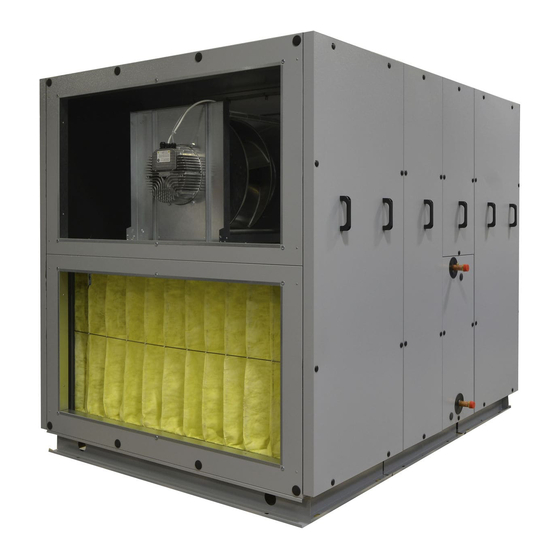
Page 5: Main Components
(except for 700 series that has a supply cable of CEE 7/16 “Europlug“ type) External temperature sensor (CT-ROM) (shielded twin cable max. 50 m) Unit controls box Filters Removable panels access to the unit Condensate drain Fans 2VV. Creating innovative solutions for you and your business since 1995. -
Page 6: Dimensions
4. DIMENSIONS ALFA 85 700 V - right version with duct system connection from the side 1 66 ALFA 85 700 V - left version with duct system connection from the top Water heater /C-O (change over) external module for units ALFA 85 700... - Page 7 1075 4. DIMENSIONS ALFA 85 700 U - right version with duct system connection from the top 1076 POWER PLAY 700V Operational diagram 1075 Funktionsschema Fan / Ventilator Heat exchanger / Wärmetauscher Filter / Filter Regulation / die Regulation Condesate exhaust /...
- Page 8 4. DIMENSIONS ALFA 85 1000 U - right version with duct system connection from the top 1416 ALFA 85 1000 Ø A Ø C heater/cooler G 3/4" G 3/4" water heater G 1/2" G 1/2" direct evaporator 5/8" 5/8" ALFA 85 1000 U – left version with duct system connection from the top...
- Page 9 4. DIMENSIONS ALFA 85 1500/2000 U/V - right version with duct system connection from the top 1518 1518 ALFA 85 1500/2000 Ø A Ø C heater/cooler G 1" G 1" water heater G 3/4" G 3/4" direct evaporator 1 1/8"...
- Page 10 4. DIMENSIONS ALFA 85 3000/4500 V - right version with duct system connection from the side ALFA 85 3000/4500 Ø A Ø C heater/cooler G 1" G 1" 1060 water heater G 3/4" G 3/4" 1060 direct evaporator 1 3/8"...
- Page 11 4. DIMENSIONS ALFA 85 3000/4500 U - right version with duct system connection from the top 1241 1212 1822 1241 1172 1212 1822 1172 ALFA 85 3000/4500 Ø A Ø C heater/cooler G 1" G 1" 1060 water heater G 3/4"...
- Page 12 4. DIMENSIONS ALFA 85 3000/4500 U - left version with duct system connection from the top 1241 1822 1212 1172 1153 ALFA 85 3000/4500 Ø A Ø C heater/cooler G 1" G 1" 1060 water heater G 3/4" G 3/4"...
- Page 13 4. DIMENSIONS ALFA 85 5500/7500 V - right version with duct system connection from the side 1520 1930 1224 1200 ALFA 85 5500/7500 Ø A Ø C PP55,70HRSECW G 1 1/2" G 1 1/2" heater/cooler 1 1/2" 1 1/2" PP55,70HRSECV G 3/4"...
- Page 14 4. DIMENSIONS ALFA 85 5500/7500 V - left version with duct system connection from the side 1558 1558 1518 1518 1292 1292 ALFA 85 5500/7500 Ø A Ø C heater/cooler 1 1/2" 1 1/2" water heater 3/4" 3/4" direct evaporator 1 5/8"...
- Page 15 4. DIMENSIONS ALFA 85 9000/12000 V - right version with duct system connection from the side 2250 1800 1760 1720 1398 1424 1020 PP085, PP100 T PP085, PP100 CO G 2" G 2" PP085, PP100 DX 1 1/8" 2 1/8"...
- Page 16 4. DIMENSIONS ALFA 85 9000/12000 V - left version with duct system connection from the side 1800 2250 1760 1720 1398 1260 1460 1424 PP085, PP100 T PP085, PP100 CO G 2" G 2" PP085, PP100 DX 1 1/8" 2 1/8"...
-
Page 17: Technical Parameters
(m3/h) 1000 1600 1500 2500 2000 3000 1000 1,63 3000 4500 1700 4500 5500 V 1850 5500 7500 V 2730 7000 9000 V 3450 8500 12000 V 5700 10000 2VV. Creating innovative solutions for you and your business since 1995. - Page 18 13,05 2,13 22,66 9000 V 9000 63,19 31,4 9,03 3,22 28,65 1“ 12000 V 12000 69,28 10,69 3,53 38,36 1“ *Data for the fall of water 90/70Tinlet = 10°C 2VV. Creating innovative solutions for you and your business since 1995.
- Page 19 81,7 28,1 2 1/8 1 1/8 12000 V 12000 54,65 15,1 80,5 33,4 2 1/8 1 1/8 Data: Tinlet = 25°C, 70% RH, evap. temperature 5°C , coolant R410A 2VV. Creating innovative solutions for you and your business since 1995.
-
Page 20: Installation
1200 5500 1500 7500 1500 9000 1500 12000 1500 The unit should use air flow with temperatures between • -20°C to +60°C and relative humidity up to 90 %. 2VV. Creating innovative solutions for you and your business since 1995. - Page 21 (do not burn, but decompose – e.g. drywall). These materials must not cover unit inlets and outlets. Safe distance of less flammable materials from unit exhalations is 500 mm. • Safe distance of flammable materials in all directions from the unit is 100mm • 2VV. Creating innovative solutions for you and your business since 1995.
- Page 22 The unit must be mounted to the frame so it cannot move accidentally. Please note when attempting to move the unit it is necessary to use a proper lifting device (e.g. forklift) 2VV. Creating innovative solutions for you and your business since 1995.
- Page 23 The unit must be mounted to the frame so it cannot move accidentally. Please note when attempting to move the unit it is nece- ssary to use a proper lifting device (e.g. forklift) 2VV. Creating innovative solutions for you and your business since 1995.
- Page 24 ALFA 85 1500-2000 V, ROOF-HR85-150-200 600-2500 de housse de pluie, PP2 1600 - 2500 m3/h, vertical 1730 30,8 ie, PP2 3000 - 4500 m3/h, vertical ALFA 85 3000-4500 V, ROOF-HR85-300-450 2020 2VV. Creating innovative solutions for you and your business since 1995.
- Page 25 9000 12000 ALFA 85 U w/o heating / w. water ALFA 85 w. el. heating /DX /C-O heating ( kg ) ( kg ) 1000 1500 2000 3000 4500 2VV. Creating innovative solutions for you and your business since 1995.
- Page 26 Connection of pressure sensors is made in the module no.2 (fig..2. -2b) using tube connectors. Individual hoses must run from modules no.1 and 3 to the module no.2, which they co- nnect in according to the numerical indication. 2VV. Creating innovative solutions for you and your business since 1995.
- Page 27 To connect all conductors and tubing it is necessary to leave the limits of each module a gap of about 20cm between the modules. Installing the unit modules 20cm 2VV. Creating innovative solutions for you and your business since 1995.
- Page 28 6. INSTALLATION Water exchanger sensor connection Air temperature sensor connection 2VV. Creating innovative solutions for you and your business since 1995.
- Page 29 6. INSTALLATION Motor connections and temperature sensors 2VV. Creating innovative solutions for you and your business since 1995.
- Page 30 The pressure measurement tubing is connected by threading the tubes through the bu- shings in the middle module. Connect the tubing in the outer module according to the numbers affixed to the tubing. ModuL 3 2VV. Creating innovative solutions for you and your business since 1995.
- Page 31 6. INSTALLATION ModuL 2 Thread the tubing according to the figure below Connect tubing to numbers. 2VV. Creating innovative solutions for you and your business since 1995.
- Page 32 6. INSTALLATION Motor and temperature sensor connection 2VV. Creating innovative solutions for you and your business since 1995.
- Page 33 6. INSTALLATION Motor and temperature sensor connection 2VV. Creating innovative solutions for you and your business since 1995.
- Page 34 Push the power cable with bushing into the middle mo- Wires are marked with wiring number dule where controls are located The wiring diagram is on the controls cover. 2VV. Creating innovative solutions for you and your business since 1995.
- Page 35 6. INSTALLATION Module Connections M8...12 fIxIng wIres 2VV. Creating innovative solutions for you and your business since 1995.
- Page 36 6. INSTALLATION 6.2 connectIng AIr InLets ALFA 85 700 U ALFA 85 1000 V ALFA 85 700 V ALFA 85 1500/2000 U ALFA 85 1000 U ALFA 85 1500/2000V 2VV. Creating innovative solutions for you and your business since 1995.
- Page 37 6. INSTALLATION 6.2 connectIng AIr InLets LFA 85 3000/4500 U ALFA 85 3000/4500 V ALFA 85 5500/7500 V, 9000/12000 V 2VV. Creating innovative solutions for you and your business since 1995.
- Page 38 Accessories must be order seperately. Rectangle/circle adapter Type Code 3000, 4500 U PR-VO-0400X400-D500-L300 Rectangle/circle adapter Type Code 3000, 4500 V PR-VO-0600X500-D560-L300 Rectangle/circle adapter Type Code 5500, 7500 V PR-O-1200X600-D630-L600 2VV. Creating innovative solutions for you and your business since 1995.
- Page 39 6. INSTALLATION Rectangle/circle adapter Type Code 9000, 12000 PR-O-1400X700-D710-L600 2VV. Creating innovative solutions for you and your business since 1995.
- Page 40 Set the dampers to be closed when the unit is off and open when the is in operation. Wrong damper postions could da- mage the unit. 2VV. Creating innovative solutions for you and your business since 1995.
- Page 41 6.3-1 Connecting supply cable Connection of the power supply cable is located in the main power switch area . Units ALFA 85 of 700 series have no main power switch but a euro terminal to connect to the mains of CEE 7/16 type.
- Page 42 B (3-4) HEAT PUMP CONTROL settable (output - ON/OFF) УПРАВЛЕНИЕ ТЕПЛОВОГО НАСОСА устанавливаемый (выход - ON/OFF) 2VV. Creating innovative solutions for you and your business since 1995. (3-4) HEAT PUMP CONTROL settable (output - ON/OFF) УПРАВЛЕНИЕ ТЕПЛОВОГО НАСОСА устанавливаемый (выход - ON/OFF)
- Page 43 ŘÍZENÍ TEPELNÉHO ČERPADLA nastavitelné (výstup - ON/OFF) й (выход - ON/OFF) ŘÍZENÍ TEPELNÉHO ČERPADLA nastavitelné (výstup - ON/OFF) 2VV. Creating innovative solutions for you and your business since 1995. ЕВАТЕЛЯ (0-10В или PWM) VÝSTUP REGULACI VÝKONU DOHŘEVU (0-10V nebo PWM) ADIABATICKÝ...
- Page 44 19 20 21 22 23 24 21 22 23 24 25 26 25 26 27 28 29 30 27 28 29 30 31 32 33 31 32 33 B-v1 B-v1 2VV. Creating innovative solutions for you and your business since 1995.
- Page 45 Fix the control panel to the wall • tilation capacity. Close and screw up the control panel case • 2VV. Creating innovative solutions for you and your business since 1995.
- Page 46 • PVC discharge pipe • discharge pipe sealing ATTENTION! For units with change-over / direct evaporator DX, bal air trap BOOST must be used. Regular air trap Air trap with a ball 2VV. Creating innovative solutions for you and your business since 1995.
- Page 47 Make sure that the unit level is 3° to provide free flow of condensate discharge. • Before putting the unit into operation, fill in the trap with water!!! Otherwise there is a risk of flooding and damage to the unit. • 2VV. Creating innovative solutions for you and your business since 1995.
-
Page 48: First Operation
(ON= red OFF= green). After activation, the display on the control panel lights up and data download will start. After complete download of these data, the unit is ready for operation. 2VV. Creating innovative solutions for you and your business since 1995. -
Page 49: Maintenance
700 U FILTR-HR85-U070 F7 1000 V FILTR-HR85-V100 F7 1000 U FILTR-HR85-U100 F7 1500,2000 V/U FILTR-HR85-VU150-VU200 F7 3000, 4500 V/U FILTR-HR85-VU300-VU450 F7 5500,7500 V FILTR-HR85-V550-V750 F7 9000, 12000 V FILTR-HR85-V900-V12K F7 2VV. Creating innovative solutions for you and your business since 1995. -
Page 50: Service
Failure of rotary heat ex- Check that the input error is correctly exchanger changer connected to the electronics or check what type of error the heat exchanger is indicating. 2VV. Creating innovative solutions for you and your business since 1995. - Page 51 Check that the sensor is correctly co- water sensor of failure nnected to the electronics or test it exchanger measuring its resistance (the resistance (T_WATER_OUT) value at +20°C is around 10kW) 2VV. Creating innovative solutions for you and your business since 1995.
- Page 52 Check the connection of the sensor. Set its address Check that it is not flooded. Replace if necessary. 2VV. Creating innovative solutions for you and your business since 1995.
- Page 53 2VV. Creating innovative solutions for you and your business since 1995.
- Page 54 5. The belt end is then detached from the wheel shell and both ends are connected using the clamp (already inserted in one end) 6. Tighten the belt using a driving pulley 2VV. Creating innovative solutions for you and your business since 1995.
-
Page 55: Faults Removal
• Serial number, service period • Accessories used, unit location • Connection conditions (also electrical connection) • Detail fault description and steps take for its removal • 2VV. Creating innovative solutions for you and your business since 1995. -
Page 56: Wiring Diagram
13 14 15 16 17 18 19 20 21 22 23 24 12 13 14 15 16 17 18 12 13 14 15 16 17 18 I-BUS I-BUS OUTPUT OUTPUT 2VV. Creating innovative solutions for you and your business since 1995. - Page 57 13 14 15 16 17 18 19 20 21 22 23 24 12 13 14 15 16 17 18 12 13 14 15 16 17 18 I-BUS I-BUS OUTPUT OUTPUT 2VV. Creating innovative solutions for you and your business since 1995.
- Page 58 12 13 14 15 16 17 18 12 13 14 15 16 17 18 I-BUS I-BUS OUTPUT OUTPUT Water pump for coil #1 24V GND GND W.PUMP 230V Postheater 2VV. Creating innovative solutions for you and your business since 1995.
- Page 59 12 13 14 15 16 17 18 12 13 14 15 16 17 18 I-BUS I-BUS OUTPUT OUTPUT Water pump for coil #1 24V GND GND W.PUMP 230V Postheater 2VV. Creating innovative solutions for you and your business since 1995.
- Page 60 12 13 14 15 16 17 18 12 13 14 15 16 17 18 I-BUS I-BUS OUTPUT OUTPUT Water pump for coil #1 24V GND GND W.PUMP 230V Postheater 2VV. Creating innovative solutions for you and your business since 1995.
- Page 61 13 14 15 16 17 18 19 20 21 22 23 24 12 13 14 15 16 17 18 12 13 14 15 16 17 18 I-BUS I-BUS OUTPUT OUTPUT 2VV. Creating innovative solutions for you and your business since 1995.
- Page 62 13 14 15 16 17 18 19 20 21 22 23 24 12 13 14 15 16 17 18 12 13 14 15 16 17 18 I-BUS I-BUS OUTPUT OUTPUT 2VV. Creating innovative solutions for you and your business since 1995.
- Page 63 13 14 15 16 17 18 19 20 21 22 23 24 12 13 14 15 16 17 18 12 13 14 15 16 17 18 I-BUS I-BUS OUTPUT OUTPUT Water pump for coil #2 W.PUMP 230V Postheater 2VV. Creating innovative solutions for you and your business since 1995.
- Page 64 12 13 14 15 16 17 18 12 13 14 15 16 17 18 I-BUS I-BUS OUTPUT OUTPUT Water pump for coil #1 24V GND GND W.PUMP 230V Postheater 2VV. Creating innovative solutions for you and your business since 1995.
-
Page 65: Conclusion
KONTAKT Adresa 2VV, s.r.o., Fáblovka 568, 533 52 Pardubice, Česká republika Internet : http://www.2vv.cz/ 2VV. Creating innovative solutions for you and your business since 1995.
Need help?
Do you have a question about the ALFA 85 and is the answer not in the manual?
Questions and answers