2VV ALFA 85 Installation Manual
Hide thumbs
Also See for ALFA 85:
- Installation and operation manual (65 pages) ,
- Quick start manual (28 pages)
Table of Contents
Advertisement
Quick Links
Advertisement
Table of Contents

Related Manuals for 2VV ALFA 85


Summary of Contents for 2VV ALFA 85
- Page 1 ALFA 85 INSTALLATION...
- Page 2 2VV. Creating innovative solutions for you and your business since 1995.
-
Page 3: Before You Start
It was assessed according to harmonized European standards listed in the relevant EC declaration of conformity were applied. For the current and full version of the EC declaration of conformity visit www.2vv.cz 2VV. Creating innovative solutions for you and your business since 1995. -
Page 4: Product Inspection
0 ° C during transport, please unpack unit and let it sit at room temperature for at least 2 hours before connecting the unit in order to balance temperature in- side unit. 2VV. Creating innovative solutions for you and your business since 1995. -
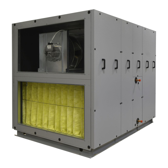
Page 5: Main Components
3. MAIN COMPONENTS Touchscreen controller UTP cable 10m Controls Filter Filter 2VV. Creating innovative solutions for you and your business since 1995. - Page 6 4. DIMENSIONS ALFA 85 700 V - right version with duct system connection from the side 27,5 27,5 27,5 27,5 Dimensions [mm] Model ALFA 85 700-V 2VV. Creating innovative solutions for you and your business since 1995.
- Page 7 4. DIMENSIONS 27,5 27,5 27,5 27,5 27,5 ALFA 85 700 U - right version with duct system connection from the top 27,5 27,5 27,5 27,5 27,5 27,5 27,5 27,5 27,5 Dimensions [mm] Model ALFA 85 700-M 2VV. Creating innovative solutions for you and your business since 1995.
- Page 8 4. DIMENSIONS ALFA 85 900 M - 2500 M - right version with duct system connection from the top 27,5 27,5 27,5 27,5 K + L D + J Dimensions [mm] Model ALFA 85 900-M 1490 867 283 1284 315...
- Page 9 4. DIMENSIONS ALFA 85 1000 V - 2500 V - right version with duct system connection from the side 27,5 27,5 27,5 27,5 Dimensions [mm] Model ALFA 85 1000-V 1470 813 294 1264 315 ALFA 85 1500-V 1500 958 1085 298...
-
Page 10: Dimensions (Mm)
4. DIMENSIONS ALFA 85 3200 V - 7000 V - right version with duct system connection from the side 27,5 24,5 24,5 27,5 24,5 24,5 27,5 27,5 Dimensions [mm] Model ALFA 85 3200-V 1625 1170 1330 370 ALFA 85 4000-V... - Page 11 4. DIMENSIONS ALFA 85 3200 U - 5000 U - right version with duct system connection from the top 27,5 24,5 24,5 27,5 27,5 24,5 24,5 27,5 27,5 24,5 24,5 27,5 27,5 24,5 24,5 27,5 Dimensions [mm] Model ALFA 85 3200-U...
- Page 12 4. DIMENSIONS ALFA 85 10K V - 14K V - right version with duct system connection from the side Rozměry [mm] PP 14000 V Model ALFA 85 10K 2000 1810 1880 500 905 1400 700 1837 1651 ALFA 85 14K...
- Page 13 4. DIMENSIONS ALFA 85 - water external modules Module DX dimensions with circular connection dimensions [mm] ALFA 85 753,5 236,5 G 1/2" 700M/V G 1/2" 32,5 255,5 2VV. Creating innovative solutions for you and your business since 1995.
- Page 14 1031,5 1062,5 333,25 434,85 107,5 5/8“ 700M/V 1/2“ 32,5 255,5 1000V 5/8“ 32,5 255,5 900M/1200M 5/8“ 32,5 255,5 1500/1600M/2000V/M 3/4“ 400,5 32,5 89,5 255,5 2500M/V 7/8“ 32,5 89,5 255,5 2VV. Creating innovative solutions for you and your business since 1995.
- Page 15 G 1" 700M/V G 3/4" 32,5 255,5 1000V G 3/4" 32,5 255,5 900M/1200M G 3/4“ 32,5 255,5 1500/1600M/2000V/M G 1" 400,5 32,5 89,5 255,5 2500M/V G 1" 32,5 89,5 255,5 2VV. Creating innovative solutions for you and your business since 1995.
- Page 16 1302,5 1345 5000M/V 1358 875,5 Ø8 1402,5 1445 3200M/V 5/8“ 1 1/8“ 1092 110,5 255,5 4000M/V 5/8“ 1 1/8“ 1184 255,5 1063 5000M/V 5/8“ 1 3/8“ 1284 246,5 1163 2VV. Creating innovative solutions for you and your business since 1995.
- Page 17 Ø8 1402,5 1445 3200M/V G 1" G 1" 1092 110,5 255,5 4000M/V G 1" G 1" 1184 255,5 1063 5000M/V G 1 1/2" G 1 1/2" 1284 246,5 1163 2VV. Creating innovative solutions for you and your business since 1995.
- Page 18 4. DIMENSIONS ALFA 85 T7000 - DX external module with rectangular connection Module DX dimensions with rectangular connection dimensions [mm] ALFA 85 7000V 1610 975,5 1653,5 1700 1200 1224 7000V 1534 2 x 5/8“ 2 x 1 1/8“ 2VV. Creating innovative solutions for you and your business since 1995.
- Page 19 4. DIMENSIONS ALFA 85 T7000 - CO external module with rectangular connection Module CO dimensions with rectangular connection dimensions [mm] ALFA 85 7000V 1610 975,5 1653,5 1700 1200 1224 7000V 1534 G 1 1/2" G 1 1/2" 2VV. Creating innovative solutions for you and your business since 1995.
- Page 20 ALFA 85 10K - external modules with rectangular connection dimensions (mm) ALFA 85 1810 1114 1853,5 1896 1400 1424 1734 ALFA 85 10K heater/cooler (C/O) G 1 1/2" G 1 1/2" direct evaporator (DX) 2VV. Creating innovative solutions for you and your business since 1995.
- Page 21 ALFA 85 14K - external modules with rectangular connection dimensions (mm) ALFA 85 2160 1168 1289 2203 2245 1400 1424 2084 ALFA 85 14K heater/cooler (C/O) G 2" G 2" direct evaporator (DX) 2VV. Creating innovative solutions for you and your business since 1995.
-
Page 22: Technical Parameters
ALFA 85 4000 50/60 17,0 25,2 ALFA 85 5000 50/60 20,3 29,9 ALFA 85 7000 50/60 32,7 48,2 ALFA 85 10000 50/60 42,7 62,6 ALFA 85 14000 50/60 58,9 87,0 2VV. Creating innovative solutions for you and your business since 1995. - Page 23 4500 2480 IP 55 ALFA 85 10000 50/60 4500 2480 IP 55 ALFA 85 14000 50/60 5700 2250 IP 55 We reserve the right to change specifications without notice. 2VV. Creating innovative solutions for you and your business since 1995.
-
Page 24: Installation
1000 ALFA 85 2500V/U 1000 ALFA 85 3200V/U 1200 ALFA 85 4000V/U 1300 ALFA 85 5000V/U 1400 ALFA 85 7000V 1600 ALFA 85 10000 2200 ALFA 85 14000 2500 2VV. Creating innovative solutions for you and your business since 1995. - Page 25 The safe distance of flammable materials from the entry neck of the unit is 500 mm. • The safe distance of flammable materials in the remaining directions is 100 mm. • 2VV. Creating innovative solutions for you and your business since 1995.
- Page 26 1795 1265,5 46,5 T5000V 1905 1365,5 114,5 46,5 T7000V 2005 1615,5 127,5 46,5 T10000 2068 1804 136,2 46,5 T14000 2218 2154 154,6 46,5 ALFA 85 1000 V - 7000V 2VV. Creating innovative solutions for you and your business since 1995.
- Page 27 T10000V T14000V 1150 1175 1210 ALFA 85 upper connection units weights Heating type Standard Model Electric [kg] Water [kg] [kg] T700M T900M T1200M T1600M T2000M T2500M T3200M T4000M T5000M 2VV. Creating innovative solutions for you and your business since 1995.
- Page 28 Pass the four bled together. hoses from the module no.1 through the grommet in the module no.2 fig. 1 2VV. Creating innovative solutions for you and your business since 1995.
- Page 29 Take extra care to avoid damaging cables and hoses! After re-checking the wiring, the panels can be put back. 2VV. Creating innovative solutions for you and your business since 1995.
- Page 30 Accessories must be order seperately. Rectangle/circle adapter ALFA 85 Code PR-VO-0400X400-D500- 3200, 4000 U L300 Rectangle/circle adapter ALFA 85 Code PR-VO-0600X500-D560- 3200 V L300 Rectangle/circle adapter ALFA 85 Code PR-O-1200X600-D630- 7000 V L600 2VV. Creating innovative solutions for you and your business since 1995.
- Page 31 CZ-53 1) ZAJISTIT TĚSNOST V ROZÍCH - TMELIT DŮVOD ZMĚNY: HMOTNOST ČISTÁ: 17999.0 g PŘESNOST: ISO2768-mK NÁZEV MATERIÁLU: 2VV. Creating innovative solutions for you and your business since 1995. TOLEROVÁNÍ: POZ.PL.0,80Sx1250x2500FS DRSNOST: ČÍSLO MATERIÁLU: KRESLIL: Martin Poslušný V PL-ZN-0,8-2,50x1,25 DATUM: 14.03.2017...
- Page 32 Set the dampers to be closed when the unit is off and open when the is in operation. Wrong damper postions could damage the unit. 2VV. Creating innovative solutions for you and your business since 1995.
- Page 33 3 mm. The unit must be connected in the manner to be able to disconnect it from the electric power supply using a single power switch. 2VV. Creating innovative solutions for you and your business since 1995.
-
Page 34: Electrical Accessories
ВНЕШНЕЕ УПРАВЛЕНИЕ ON/OFF (вход NC) (5-6) ADIABATIC MODULE (output - ON/OFF) АДИАБАТИЧЕСКИЙ МОДУЛЬ (выход - ON/OFF) 2VV. Creating innovative solutions for you and your business since 1995. B (3-4) HEAT PUMP CONTROL settable (output - ON/OFF) УПРАВЛЕНИЕ ТЕПЛОВОГО НАСОСА устанавливаемый (выход - ON/OFF) - Page 35 EXTERNÍ OVLÁDÁNÍ ON/OFF (vstup NC) й (выход - ON/OFF) ŘÍZENÍ TEPELNÉHO ČERPADLA nastavitelné (výstup - ON/OFF) 2VV. Creating innovative solutions for you and your business since 1995. й (выход - ON/OFF) ŘÍZENÍ TEPELNÉHO ČERPADLA nastavitelné (výstup - ON/OFF) ЕВАТЕЛЯ (0-10В или PWM) VÝSTUP REGULACI VÝKONU DOHŘEVU (0-10V nebo PWM)
- Page 36 21 22 23 24 21 22 23 24 25 26 25 26 27 28 29 30 27 28 29 30 31 32 33 31 32 33 B-v1 B-v1 B-v1 B-v1 2VV. Creating innovative solutions for you and your business since 1995.
-
Page 37: Control Unit
Cut a hole for the cable • Insert the control cable to the connector of the remote • control Fix the control panel to the wall • Close the control panel case • 2VV. Creating innovative solutions for you and your business since 1995. -
Page 38: Connecting Condensate Drain
• PVC discharge pipe • discharge pipe sealing ATTENTION! For units with change-over / direct evaporator DX, bal air trap must be used. Regular air trap Air trap with a ball 2VV. Creating innovative solutions for you and your business since 1995. -
Page 39: First Operation
(ON= red OFF= green). After acti- vation, the display on the control panel lights up and data download will start. After complete download of these data, the unit is ready for operation. 2VV. Creating innovative solutions for you and your business since 1995. -
Page 40: Maintenance
YOU WILL NEED 1) Open the cover 2) Remove the air filter 3) Replace the air filter according to the unit type 2VV. Creating innovative solutions for you and your business since 1995. -
Page 41: Replacement Procedure
Location of the safety thermostat is indicated with RESET mark in each unit 2VV. Creating innovative solutions for you and your business since 1995. -
Page 42: Replacing The Fans
5. Push the both ends at least 30 seconds against each other. 6. Remove the protruding ring with knife. 7. Tighten the belt using a driving pulley. 2VV. Creating innovative solutions for you and your business since 1995. -
Page 43: Replacing The Main Control Board
4. Then pull the whole coil out of the unit. 5. Place the new coil to the unit. Connect the connector of the temperature sensor(s)! 6. Screw on the bolts fixing the panel. 2VV. Creating innovative solutions for you and your business since 1995. - Page 44 13 - Failure of rotary heat Failure of rotary heat ex- connected to the electronics or check Unit is not working exchanger changer what type of error the heat exchanger is indicating. 2VV. Creating innovative solutions for you and your business since 1995.
- Page 45 Room temperature sensor cted to the electronics or test it measuring water sensor of exchanger Unit is not working failure its resistance (the resistance value at (T_WATER_OUT) +20°C is around 10kW) 2VV. Creating innovative solutions for you and your business since 1995.
- Page 46 Check the connection of the sensor. Set its address Check that it is not flooded. Replace if necessary. 2VV. Creating innovative solutions for you and your business since 1995.
- Page 47 Unit is not working rrectly, or whether the condensate drain flow of water in the condenser's is not clogged, preventing the condensate from draining correctly. 2VV. Creating innovative solutions for you and your business since 1995.
- Page 48 • Serial number, service period rectives. • Accessories used, unit location • Connection conditions (also electrical connection) • Detail fault description and steps take for its removal • 2VV. Creating innovative solutions for you and your business since 1995.
-
Page 49: Wiring Diagram
13 14 15 16 17 18 19 20 21 22 23 24 12 13 14 15 16 17 18 12 13 14 15 16 17 18 I-BUS I-BUS OUTPUT OUTPUT 2VV. Creating innovative solutions for you and your business since 1995. - Page 50 13 14 15 16 17 18 19 20 21 22 23 24 12 13 14 15 16 17 18 12 13 14 15 16 17 18 I-BUS I-BUS OUTPUT OUTPUT 2VV. Creating innovative solutions for you and your business since 1995.
- Page 51 12 13 14 15 16 17 18 12 13 14 15 16 17 18 I-BUS I-BUS OUTPUT OUTPUT Water pump for coil #1 24V GND GND W.PUMP 230V Postheater 2VV. Creating innovative solutions for you and your business since 1995.
- Page 52 12 13 14 15 16 17 18 12 13 14 15 16 17 18 I-BUS I-BUS OUTPUT OUTPUT Water pump for coil #1 24V GND GND W.PUMP 230V Postheater 2VV. Creating innovative solutions for you and your business since 1995.
- Page 53 12 13 14 15 16 17 18 12 13 14 15 16 17 18 I-BUS I-BUS OUTPUT OUTPUT Water pump for coil #1 24V GND GND W.PUMP 230V Postheater 2VV. Creating innovative solutions for you and your business since 1995.
- Page 54 CONTACT Address 2VV, s.r.o., Fáblovka 568, 533 52 Pardubice, Czech Republic Internet : http://www.2vv.cz/ 2VV. Creating innovative solutions for you and your business since 1995.
Need help?
Do you have a question about the ALFA 85 and is the answer not in the manual?
Questions and answers