Truma CP plus Manual
- Operating instructions manual (96 pages) ,
- Installation instructions manual (32 pages) ,
- Operating and installation instructions (14 pages)
Advertisement
- 1 About these instructions
- 2 Intended use
- 3 Method of operation
- 4 Menu control
-
5
Operation
- 5.1 Initial start-up
- 5.2 Start-up
- 5.3 Switching on/off
- 5.4 App mode with iNet Box
- 5.5 Setting the room temperature
- 5.6 Selecting the water temperature
- 5.7 Selecting the energy type
- 5.8 Fan / circulated air mode
- 5.9 Switching lighting on / off
- 5.10 Setting the time
- 5.11 Time control
- 5.12 Service menu
- 6 Special displays
- 7 Warning
- 8 Malfunction
- 9 Maintenance
- 10 Technical data
- 11 Troubleshooting guide
- 12 Safety instructions
- 13 Documents / Resources
About these instructions
- These instructions are part of the product
- Always carry the operating instructions in the vehicle
- Also make the safety instructions available to other users
Document number
The document number of these instructions can be found in the footer of every inside page and on the back page
The document number consists of
- Part number (10 digits)
- Revision status (2 digits)
- Publication date (month/year)
Validity
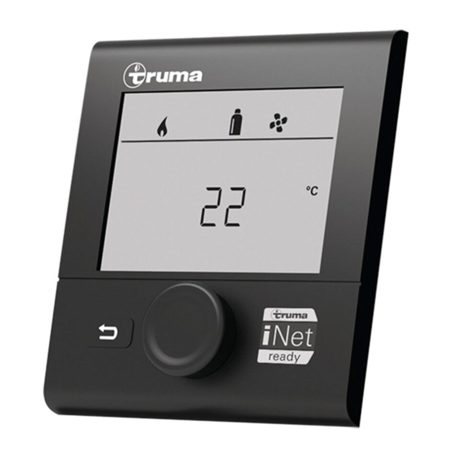
These instructions apply to the Truma CP plus control panel, referred to a CP plus below
Product names
Aventa eco and Aventa comfort are referred to as Aventa below
Truma iNet Box is referred to as iNet Box below About these instructions
Target group
These instructions are intended for users
 To make the text easier to read, no gender-specific distinction is made
Symbols and means of representation
| Symbol | Meaning |
 |  about dangers to persons |
 | Expert |
| | Additional information to provide a better understanding or to optimise work processes |
| | Symbol for an action. Something must be done here |
| * | Optional parts |
| (Fig. 3-1) | Reference to a picture e.g. Figure 3 - number 1 |
Intended use
Proper use
The CP plus[1] is used to control and monitor a Combi heater and/or a Truma air conditioning system The CP plus 1 acts as an interface to operate connected appliances via the Truma App and iNet Box
The CP plus1 is intended for installation in caravans and motor homes
Inappropriate use
Installation in boats is not permitted
Method of operation

- CP plus
- Combi (D)
- Air conditioning system
- Heater mode (HEATER)
- Air conditioner mode (AC)
- Automatic climate control mode (AUTO)
Controlling connected appliances / operating mode
To control the room temperature, the CP plus controls either the connected heater or air conditioning system When a new or replacement appliance (Combi (D), air conditioning system or Truma iNet Box) is connected to the bus system, repeat the procedure described in "Initial start-up"
If a heater and air conditioning system are connected at the same time, select the required mode, heater (HEATER) or air conditioning system (AC) before setting the room temperature Alternatively, you can activate the automatic climate control mode (AUTO), see "Service menu". The CP plus then switches automatically between heater and air conditioning system This ensures an almost even indoor temperature By default, automatic climate control is switched off
If the 230 V power supply (mains electricity) is interrupted, all functions associated with the air conditioning system or automatic climate control modes are deactivated and blanked out on the CP plus
The function of the Truma automatic climate control depends on correct installation Your Truma Partner will be pleased to advise you whether your vehicle is suitable
Requirements for the automatic climate control functioning as expected:
- The air conditioning system and heater cover the entire area of the vehicle that is intended to be automatically air conditioned
- The room temperature sensor of the heater is the lead sensor of the automatic climate control and must therefore be in a suitable location, ie
- in the area in which the required room temperature should be reached
- if possible, not influenced by outside temperature or sunlight
- not close to warm air ducts, cold air ducts or other sources of heat or cold
- warm or cold air from the air outlets must not flow against the room temperature sensor Particular attention must be paid to this when adjusting the air throttles on Aventa air conditioning systems
- with good circulation and not on the vehicle ceiling
Truma Partners are trained in the correct installation of automatic climate control
You will find our authorised dealers / Truma Partners at www.truma.com
Time control
In addition to normal operation, a time switch can also be used A time switch can be set for all operating parameters To do this, set a start time (1) and an end time (2) In normal operation, outside the time control (B), the operating parameters that were set previously remain valid (A)

If you change a parameter during the timer interval, it will remain changed until the end time After this, the parameters are reset for normal operation
The timer repeats every 24 hours
Using CP plus and IR remote control for the air conditioning system together

- CP plus
- Combi (D)
- Air conditioning system
- IR receiver
- Air distributor
- IR remote control
Even when the CP plus is connected, the IR remote control can still be used to control the air conditioning system The CP plus detects all settings on the air conditioning system that were set via the IR remote control The IR remote control sends only the settings shown on your screen (no bidirectional communication)
Use only the CP plus time switch to define the start and end time of a required period
Using CP plus and iNet Box together

- iNet Box
- Mobile device with Truma App
- CP plus
- Heater
- Air conditioning system
In app mode, the connected appliances and the Truma CP plus go to stand-by mode and wait for new commands from the connected iNet Box
When a new command is entered via the Truma App, the connected appliances and the Truma CP plus are activated with the specified values
When a new or replacement Truma iNet Box is connected to the bus system, repeat the procedure described in "Initial start-up".Then activate the app mode, see "App mode with iNet Box"
The time switch is disabled in app mode
Menu control

- Display
- Status bar
- Menu bar (top)
- Menu bar (bottom)
- 230 V power supply indicator (mains electricity)
- Time switch indicator
- Settings / values ("displayed text")
- Rotary push button
- Back button
Selecting a menu item
The backlit screen shows the menu level The first icon flashes

Use the rotary push button to select menus in the menu bar and make settings
| Symbol | Menu item |
 | Setting the room temperature |
 | Selecting the hot water level |
 | Selecting the energy type |
 | Selecting the fan level |
 | Setting the time switch |
 | Switching lighting on / off |
 | Error message |
 | Setting the time |
 | Service menu |

Turn the rotary push button clockwise
- Menu is run through from left to right

Turn the rotary push button anti-clockwise
- Menu is run through from right to left

Press the rotary push button
- Select a menu item, switch to setting level
Setting a parameter

The backlit screen shows the setting level. The operating parameters of the selected menu item are shown in "Settings / values". Use the rotary push button to select and change setpoint and parameters; press the button to save these. Selected menu items flash.

Turn the rotary push button clockwise
- Increase values (+)

Turn the rotary push button anti-clockwise
- Decrease values (-)

Press the rotary push button
- Apply (save) a selected value
Exiting the menu and/or settings level
![]()
Press the Back button
- Go back from a menu
- Go back from the setting levThe backlit screen shows the setting level The operat-el and reject settings; in other ing parameters of the selected menu item are shown in words, the previous values remain "Settings / values" Use the rotary push button to select unchanged
Displaying saved settings / activated functions

Saved settings and activated menu items are shown in the status line
If the power supply is interrupted, these settings are deleted (exception: stored appliances)
Operation
Initial start-up
In order to perform the initial start-up, the following steps are required:
- Switch on the power supply
- 12 V for CP plus and Combi and
- 230 V power supply for air conditioning system and Combi E
- Start searching for appliances under the menu item "Service menu" -> "RESET" -> "PR SET"
After confirmation, the Truma CP plus initialises itself "INIT " appears on the display while this is in progress The appliances that are found are stored in the Truma CP plus
Start-up
Once you have connected the Truma CP plus to the power supply, a start screen opens after a few seconds

The display changes between the time and the set room temperature
After a repair / retrofit, the procedure described under "Initial start-up" must be repeated
Special displays when commands are entered via the Truma App, IR remote control of the air conditioning system or CI bus (see "Special displays")
Switching on/off
Switching on
![]()
Press the rotary push button
- Previously set values / operating parameters are reactivated after switching on
Switching off
![]()
Press the rotary push button for more than 4 seconds.
- After 2 seconds, "APP" is displayed on the screen (if iNet Box is connected)
- "OFF" appears after another 2 seconds
- Due to internal time lags of the heater or air conditioning system, it may take a few minutes for the Truma CP plus to switch off
If you park your vehicle in an enclosed space or if you will not be using it for an extended period, during winter for example, you must switch off the CP plus
App mode with iNet Box
Switch on app mode
- Press the rotary push button for about 2 seconds until "APP" appears on the screen
- Release the rotary push button
Ending app mode
If no commands are entered via the Truma App, app mode can be closed on the Truma CP plus
- Briefly press the rotary push button
The saved values are then applied next time it is put into operation
Setting the room temperature
The room temperature setting depends on the operating mode (HEATER, AC, AUTO) You must select the mode before setting the room temperature (This is unnecessary if just one appliance is connected to the CP plus) Each operating mode has its own adjustable room temperature range In other words, different room temperature ranges can be selected in heating, cooling or automatic mode
| Mode | Adjustable temperature range |
| Heater (HEATER) | 5 – 30°C (1°C increments) |
| Air conditioning (AC) | 16 – 31°C (1°C increments) |
| Automatic climate control (AUTO) | 18 – 25°C (1°C increments) |
- Use the rotary push button to select
![]() in the menu line
in the menu line - Press the rotary push button to go to the setting level
- Depending on the appliance that is connected, choose between heater (HEATER), air conditioning system (AC) or automatic climate control (AUTO), using the rotary push button (Not necessary if just one appliance is connected)
- Press the rotary push button to confirm your selection
- Select the desired temperature with the rotary push button
- Press the rotary push button to confirm the value
During heating / cooling, you can change the temperature quickly on the stand-by screen, using the rotary push button without opening the menu
Special features in air conditioning (AC) and automatic climate control (AUTO) modes
If the 230 V power supply (mains electricity) is interrupted, all functions associated with the air conditioning system or automatic climate control modes are deactivated and blanked out on the CP plus With automatic climate control, the Combi / Combi D is deactivated, even in heating mode When the 230 V power supply is restored, the Combi does not start automatically
Room temperature in heater mode (HEATER)
| Symbol | Displayed text | Description |
 | Heater is switched on |
To switch the heater off, select the temperature range below 5°C (OFF)
Room temperature in air conditioning mode (AC)
| Symbol | Displayed text | Description |
 | COOL | Air conditioning system is switched on |
 | AUTO (Circulated air) | Air conditioning system is set to automatic: circulated air level is selected automatically according to the cooling capacity Symbol flashes until the desired room temperature is reached |
 | HOT* | Air conditioning system is in heating mode |
 | VENT | Air conditioning system is in circulating air mode |
* Available only with some air conditioning systems
Room temperature in automatic climate control mode (AUTO)
| Symbol | Displayed text | Description |
 | AUTO (ACC) | Automatic climate control is switched on |
Selecting the water temperature
Use the rotary push button to select ![]() in the menu line
in the menu line
- Press the rotary push button to go to the setting level
- Select desired level with rotary push button
- Press the rotary push button to confirm the value
| Symbol | Displayed text | Description |
 | OFF | Water heating is switched off |
 | ECO* | Hot water temperature 40°C |
 | HOT | Hot water temperature 60°C |
 | BOOST | If room heating and water heating are switched on together, the heater is deactivated for 40 minutes. This ensures that the water is heated quickly (water has precedence). When the water temperature is reached, room heating begins again. |
* Hot water temperature may exceed 40°C with combined room and water heating Not available for the Australian variants
![]() flashes until the required water temperature is reached
flashes until the required water temperature is reached
Selecting the energy type
The energy supply for the heater can be adjusted to suit the available energy types (parking area, camp site, while driving)
The "Select energy type" menu is displayed only if a heater with electric heating elements is connected, for example Combi E CP plus ready
Depending on the ambient temperature, electrical heating power alone might not be sufficient to reach the specified room temperature Switch to mixed or gas mode to increase the heating power
The specified room temperature is reached quickest in mixed mode
- Use the rotary push button to select
![]() in the menu line
in the menu line - Press the rotary push button to go to the setting level
- Select desired energy type with rotary push button
- Press the rotary push button to confirm the value
| Symbol | Operating mode | Energy type |
 | GAS / DIESEL | Gas / Diesel |
 | MIX 1 | Mixed mode Electric (900 W) + Gas / Diesel |
 | MIX 2 | Mixed mode Electric (1800 W) + Gas / Diesel |
 | EL 1 | Electric (900 W) |
 | EL 2 | Electric (1800 W) |
When the heater is switched on (room temperature, hot water level active), the status line shows the energy type selected in the previous heating procedure The factory setting is gas / diesel
Special features in mixed mode
- Interruption of the power supply 230 V: The heating system switches automatically to gas and diesel mode When the 230 V power supply is restored, the heating automatically switches back to mixed mode
- Malfunction in combustion procedure (eg lack of fuel)
Combi Gas
The heater switches automatically to electric mode For the heater to operate in mixed mode again, rectify the cause of the malfunction and acknowledge it on the Truma CP plus See "Troubleshooting guide".
Combi Diesel
The heater shows a malfunction For the heater to operate in mixed mode again, rectify the cause of the malfunction and acknowledge it on the Truma CP plus Switch to "Electric" energy mode if the malfunction persists
Special features in electric mode
- If the 230 V power supply is interrupted and the 12 V supply is switched on, a fault code is shown on the screen
- When the 230 V power supply is restored, the heater starts automatically with the previous settings The fault code is no longer displayed
- Observe the special features in automatic climate control mode
Fan / circulated air mode
The fan is an additional function to the selected mode, heater (HEATER), air conditioning (AC) or automatic climate control (AUTO) The CP plus activates the fan of the appliance that is operating at the time (heater or air conditioning) Each connected appliance has its own fan modes
The fan can also be operated without heating or cooling (VENT)
- Use the rotary push button to select
![]() in the menu line
in the menu line - Press the rotary push button to go to the setting level
- Select the desired fan mode with the rotary push button
- Press the rotary push button to confirm the value
Fan modes with heater / water heating / air conditioning switched off
| Symbol | Displayed text | Description |
 | OFF | Fan is switched off |
Fan modes in heater mode (HEATER)
| Symbol | Displayed text | Description |
 | ECO | Low fan level |
 | HIGH | High fan level |
 | BOOST | Rapid room heating is available if the difference between the selected and current room temperatures is more than 10°C |
When the heater is switched on (room temperature, hot water level set), the status line (2) shows the fan mode that was selected the last time the heater was running The factory setting is "ECO"
Fan modes in air conditioning mode (AC)
| Symbol | Displayed text | Description |
| OFF | Fan is switched off. (can be selected only if no appliance is in operation). | |
 | LOW | Low fan level |
 | MID | Medium fan level |
 | HIGH | Highest fan level |
 | NIGHT | Ultra-quiet fan operation |
Fan modes in automatic climate control mode (AUTO)
| Symbol | Displayed text | Description |
 | AUTO | Automatic fan level selection. Cannot be changed in AUTO mode. |
Only "ECO" is available for heaters
If the 230 V power supply (mains electricity) is interrupted, all functions associated with air conditioning system or automatic climate control modes are deactivated and blanked out on the CP plus
Switching lighting on / off
Available only if an air conditioning system is connected together with a room air distributor and dimmable LED ambient lighting
- Use the rotary push button to select
![]() in the menu bar (4)
in the menu bar (4) - Tap the rotary push button to go to the setting level
- Select the required function with the rotary push button
1 – 5 – Switch lighting on Brightness selectable in 5 levels
OFF – Switch lighting off - Tap the rotary push button to confirm the value
Setting the time
- With the rotary push button (8), select the "Set time" icon in the menu bar (4) The hour display flashes
- Set the hours with the rotary push button
- Tap the rotary push button again and the minutes display flashes
- Set the minutes with the rotary push button
- Tap the rotary push button to confirm the value
In 12h mode: A: am, P: pm
Time control

Risk of poisoning from exhaust gases The activated time switch switches the heater on even when the vehicle is parked without supervision The heater's exhaust can be toxic in enclosed spaces (eg garages, workshops)
If the vehicle is parked in closed rooms:
- Shut off the fuel supply (gas or diesel) to the heater
- Switch off the CP plus to prevent the heater being switched back on by the Truma App or the time switch (see "Switching on/off")
When the air conditioning system is operating, the CP plus time switch must be used only to define the start and end times for a required period
If the time switch is activated (ON), the "Deactivate time switch" menu (OFF) is displayed first
- Use the rotary push button to select
![]() in the menu bar (4)
in the menu bar (4) - Press the rotary push button to go to the setting level
Enter the start time
- Set the hours then the minutes with the rotary push button
In 12h mode: A: am, P: pm
Enter the end time
- Set the hours then the minutes with the rotary push button
If the start/end point was exceeded during entry, the operating parameters will not apply until the next start/end point is reached Until then, the operating parameters that have been set outside the time switch remain valid
After this, you can set the following menu items that are within the switching interval:
- Setting the room temperature
- Setting the hot water level
- Selecting the energy type
- Selecting the fan level
- Activating the time switch (ON)
- Deactivating the time switch (OFF)
- Switching lighting on / off
- Setting the time
Service menu
- Use the rotary push button to select
![]() in the menu line
in the menu line - Press the rotary push button to go to the setting level
- Choose the desired setting with the rotary push button
- Press the rotary push button to confirm the value
Calibrating the room temperature sensor of the heater (OFFSET)
The room temperature sensor of the heater can be individually adjusted to the sensor's installation situation
The setting can be made in increments of 05°C from 0°C to -5°C
Example:
Set room temperature 23°C;
OFFSET = -1°C;
- Setpoint for heater = 22°C
Default setting: 0°C (Celsius)
AC SET1,2
The sensed room temperature can – during operation of the automatic climate control – be perceived differently during cooling than during heating "AC SET" is used to set an offset between cooling and heating The setting can be made in increments of 05°C from 0°C to +5°C
Example:
Set room temperature 23°C;
AC SET = 2°C
- Setpoint for air conditioning = 25°C
Default setting: +1°C (Celsius)
1 Available only if an air conditioning system and heater are connected
2 Available only if ACC is set to "ON"
ACC1
The automatic climate control function AUTO is activated or blocked with "ACC"
ON
- The automatic climate control function AUTO is activated Automatic climate control function AUTO can be selected in the room temperature menu
- "AC SET" is displayed in the Service menu
OFF
- The automatic climate control function AUTO is blocked
Default setting: OFF
°C / °F temperature display
Select the temperature display °C (Celsius) or °F (Fahrenheit)
Default setting: °C (Celsius)
Changing the background lighting
Change the background lighting of the Truma CP plus in 10 levels
12 h / 24 h mode
Display time in 12 h (a m, p m) / 24 h mode
Default setting: 24 h mode
Changing the language
Select the desired language (German, English, French, Italian)
Default setting: English
Displaying the version number
Display the version number of the heater, air conditioning system, Truma CP plus or iNetBox
Example: H 12001 -> H = Appliance; 12001 = Version number
Appliance
C = Truma CP plus
F = CP plus CI-BUS
A = Air conditioning system
H = Heater
T = Truma iNet Box
Default setting (RESET)
The reset function resets the CP plus to the default setting This deletes all settings Newly connected appliances are detected and stored in the Truma CP plus
- Switch on the power supply, 12 V for Truma CP plus and Combi and 230 V for an air conditioning system and Combi E
Reset
- Select "RESET" with the rotary push button
- Press the rotary push button
- "PR SET" is displayed
- Press the rotary push button to confirm
After confirmation, the CP plus initialises itself "INIT " appears on the display while this is in progress
Special displays
230 V power supply available
The symbol indicates that a 230 V power supply (mains electricity) is available on the connected heater and/or air conditioning system

Truma App with iNet Box
When a command is sent via the Truma App from a mobile device, "APP" is displayed
Infrared (IR) remote control (air conditioning system)
When a command is sent via the infrared remote control of the air conditioning system, "IR" is displayed
External control panel (CI-BUS)
When a command is sent via an external control panel with CI-BUS, "CI" is displayed
The CP plus CI BUS is a separate variant that is equipped only in the factory
Warning
indicates that an operating parameter has reached an undefined state In this case the appliance concerned continues to operate When the operating parameter is within the target range again, this symbol goes off again automatically
Reading out the warning code
- Select the icon with the rotary push button
- Press the rotary push button
The current warning code will be displayed Use the troubleshooting guide to determine and rectify the cause of the warning
![]()
W = Warning
42 = Fault code
H = Appliance
H = Heater
A = Air conditioning system

Cause eliminated / return to the setting level
- Press the rotary push button
Cause not eliminated / return to the setting level
- Press the Back button
In this case, the warning is not acknowledged in the CP plus and the warning symbol remains The affected appliance remains in warning status Other connected appliances can be operated
Malfunction
In the event of a malfunction, the CP plus immediately goes to the "Malfunction" menu level and displays the relevant fault code Use the troubleshooting guide to determine and rectify the cause of the malfunction

E = Malfunction
112 = Fault code
H = Appliance
H = Heater
A = Air conditioning system
Cause eliminated / return to the setting level
- Press the rotary push button If the display is in stand-by mode, press to activate the background lighting and press again to acknowledge the malfunction
- The respective appliance is restarted
This can take several minutes due to the internal after-runs of connected devices
If the cause has not been remedied, the malfunction will occur again and the CP plus will go to the "Malfunction" menu level again
If the fault code flashes in the control panel display, this cannot be reset until up to 15 minutes have elapsed
Cause not eliminated / return to the setting level
- Press the Back button
In this case, the malfunction is not acknowledged in the CP plus and the warning symbol remains The appliance remains in malfunction state Other connected appliances can be operated
Maintenance
The CP plus requires no maintenance Use a damp, non-scouring cloth to clean the front panel If this is not sufficient, use a neutral soap solution
Technical data
| Screen | LCD, monochrome, with background lighting |
| Dimensions (L x W x H) | 92 x 103 x 40 mm |
| Operating temperature range | -25°C to +60°C |
| Storage temperature range | -25°C to +70°C |
| Interfaces CP plus | TIN bus |
| CP plus CI BUS Power supply | TIN bus, CI bus 8 V – 16.5 V DC |
| Power consumption | max. 65 mA (100% background lighting) 6.5 mA – 10 mA (stand-by) |
| Quiescent current consumption | 3 mA (Off) |
| Weight Protection class | approx. 100 g Class III |
| Protection type | IP00 |
Subject to technical changes
Troubleshooting guide
If these measures do not remedy the malfunction or if fault codes are displayed that you cannot find in the troubleshooting guide, contact Truma Service.
Heater Combi / Combi E (H)
| Fault code | Cause | Remedy |
| W 17 H | Water overheat condition (woc) | Switch heater off and allow it to cool. Fill the water container with water |
| W 18 H | Air overheat condition | |
| Not all warm air ducts are connected | Make sure that all warm air ducts are connected to the heater | |
| Warm air outlets blocked | Check whether the warm air ducts are damaged or kinked | |
| Circulated air intake blocked | Remove the blockage in the circulated air intake and ensure that the installation space is sufficiently ventilated | |
| W 24 H | Imminent low voltage / battery voltage too low < 10.4 V | Check the function with the motor running, check the power supply unit or other batteries. Charge battery and check contacts, replace old battery |
| E 29 H | Power consumption of the FrostControl heating element too high | Replace FrostControl heating element |
| W 42 H | Window switch detects open window | Close window above cowl |
| E 43 H | 12 V power supply faulty (overvoltage) | Check the 12 V power supply at the appliance input under load; to test, disconnect the power supply unit and the solar system from the on-board power supply |
| W 45 H | 230 V power supply faulty | Check the 230 V power supply at the appliance input |
| Have an expert check the 230 V fuse and replace it if necessary | ||
| Reset the 230 V overheating protection (see Combi operating instructions) | ||
| E 111 H | Fault in the electronics | Check the 12 V power supply at the appliance input under load; to test, disconnect the power supply unit and the solar system from the on-board power supply |
| E 112 H, E 121 H, E 122 H, E 202 H, E 211 H, E 212 H | Flame out or not detected, Flame unstable during operation, Gas supply interrupted | Check that the gas supply has the correct operating pressure (see Fault catalogue, gas supply) |
| E122H | Lack of fuel due to low tank level, tank is empty and / or vehicle is on a slope | Fill tank with fuel and then fill the fuel line (see operating instructions / initial start-up) |
| W 255 H | Heater has no 12 V power supply | Check the 12 V power supply at the appliance input; to test, disconnect the power supply unit and the solar system from the on-board power supply |
| No connection between heater and control panel | Check the control panel cable and make sure there is connection between the heater and the control panel | |
| W 301 H, W 417 H | 12 V power supply faulty (overvoltage) | Check the 12 V power supply at the appliance input; to test, disconnect the power supply unit and the solar system from the on-board power supply |
| W 302 H, W 418 H | 12 V power supply faulty (low voltage) | Charge battery and check contacts, replace old battery |
| W 303 H, W 411 H | Risk of low voltage. Battery voltage too low < 10.4 V | Check the function with the motor running, check the power supply unit or other batteries. Charge battery and check contacts, replace old battery |
| W 401 H | Hot water mode with empty water container | Switch heater off and allow it to cool. Fill the water container with water |
| W 402 H | Air overheat condition | |
| Not all warm air ducts are connected | Make sure that all warm air ducts are connected to the heater | |
| Warm air outlets blocked | Check whether the warm air ducts are damaged or kinked | |
| Circulated air intake blocked | Remove the blockage in the circulated air intake and ensure that the installation space is sufficiently ventilated | |
| W 407 H | 230 V power supply faulty | Check the 230 V power supply at the appliance input |
| Have an expert check the 230 V 10 AF, H fuse and replace it if necessary | ||
| W 408 H | Gas supply interrupted in mixed mode | Check that the gas supply has the correct operating pressure. Start the heater in gas mode, acknowledge the fault and switch to mixed mode |
| W 412 H | Window switch detects open window | Close window above cowl |
| E 507 H, E 516 H, E 517 H | Gas supply interrupted | Check that the gas supply has the correct operating pressure (see Fault catalogue, gas supply) |
| E 607 H | Maximum number of fault resets reached / after more | Wait 15 minutes and reset fault |
| E 621 H | than 4 resets within 15 minutes, the heater is blocked Room temperature sensor or cable faulty | Check the cable for the room temperature sensor and plug connections Replace the room temperature sensor |
| E 624 H | FrostControl heating element has a short circuit | Replace FrostControl heating element |
| E 632 H | 230 V overheating protection has triggered | Reset the 230 V overheating protection (see Combi operating instructions) |
Heater Combi D / Combi D E (H)
| Fault code | Cause | Remedy |
| E 111 H | Room temperature sensor or cable faulty | Check the cable for the room temperature sensor and plug connections |
| E 121 H | Interruption in the metering pump – temperature switch has triggered |
|
| E 122 H | Lack of fuel due to low tank level, tank is empty and / or vehicle is on a slope |
|
| E 131 H | No connection between heater and control panel | Connect the heater and the control panel |
| E 132 H | FrostControl heating element has a short circuit | Ensure 12 V power supply under load at appliance input / check for AC voltage components (disconnect power supply unit and solar system from on-board power supply) |
| W 150 H | Warm air temperature exceeded |
|
| W 151 H | Water temperature exceeded in heater mode |
|
| E 152 H | Water temperature exceeded in hot water mode | Switch heater off and allow to cool, fill water container with water |
| W 160 H W 161 H | 12 V power supply faulty (low voltage) |
|
| E 162 H | Window above cowl open (window switch) | Close window above cowl |
| W 163 H | One of the temperature switches has opened | Allow the heater to cool. If this occurs frequently, contact Truma Service |
| W 164 H | 230 V power supply faulty |
|
| W 170 H | Imminent low voltage < 11.5 V |
|
| W 255 H |
|
|
|
| |
| W 301 H, W 417 H, E 540 H | 12 V power supply faulty (overvoltage) | Ensure 12 V power supply under load at appliance input / check for AC voltage components (disconnect power supply unit and solar system from on-board power supply) |
| W 302 H, W 418 H, E 541 H | 12 V power supply faulty (low voltage) |
|
| W 303 H, W 411 H | Risk of low voltage. Battery voltage too low < 10.8 V |
|
| W 423 H | Initial filling required (filling function at initial start-up) | Activate initial filling by setting a heating request with temperature settings 30°C |
| W 424 H | Initial filling active – after initial filling, the heater automatically switches to normal operation with a temperature setting of 30°C | Do not switch the heater off or interrupt the power supply during initial filling |
| E 560 H | Heater will not start. Note: The device is locked after the fifth acknowledgement of the error message. | Check the fuel supply at the appliance input |
| E 561 H | Cannot restart heater. Maximum number of start attempts reached – operating lock is activated. | Contact Truma Service |
| E 565 H | Heater will not start, flame repeatedly not detected. One more repeat start for initial filling possible | Check the fuel supply at the appliance input |
Air conditioning system (A)
| Fault code | Cause | Remedy |
| E 8 A, W 8 A | IR receiver unplugged or cable broken | Check the connection of the IR receiver |
| E 17 A, W 17 A | Voltage dip at 230 V power supply | Check 230 V power supply |
Safety instructions
General safety
- Read and closely follow safety instructions to prevent risks and damage for people and property
- Read and observe the operating instructions and supporting documents for the appliances, such as gas supply, heater, air conditioning system and the vehicle carefully and keep them in a safe place for subsequent use
- Observe local laws, guidelines and standards associated with the use and operation of the device
Safety instructions for the control panel
- The CP plus must not be operated unless it is in technically perfect condition
- Repairs must be carried out immediately Do not attempt to rectify malfunctions yourself unless this is described in the troubleshooting guide of these instructions
- Do not repair or modify the CP plus
- A faulty CP plus may be repaired only by the manufacturer or the manufacturer's service department
- Never use LP gas appliances when refuelling, in multi-storey car parks, in garages or on ferries Switch off the CP plus to prevent the heater being switched back on by the Truma App or the time switch (see "Switching on/off")
Obligations of the operator/ / vehicle owner
- Make sure that the appliance can be operated properly in all operating phases
Installation, dismantling, repositioning
Only competent, trained personnel (experts) may install and repair the Truma product and carry out the function check with consideration of the installation and operating instructions and the current recognised rules of engineering Skilled personnel refers to persons who are capable of properly carrying out the necessary work and recognising possible hazards based on their specialist training and education, their knowledge and experience with Truma products and the relevant standards
![]() For experts only
For experts only
Do not install, dismantle or reposition the device on your own.
- Have the device installed, dismantled or repositioned only by an expert
Important notes
- If the power supply to the system has been interrupted, the time / time switch must be reset
- When a new or replacement appliance (heater, air conditioning system or Truma iNet Box) is connected to the bus system, repeat the procedure described in
- "Initial start-up"
- If a Combi heater is connected to the CP plus, you can no longer use the time switch ZUCB
Documents / Resources
References
Download manual
Here you can download full pdf version of manual, it may contain additional safety instructions, warranty information, FCC rules, etc.
Advertisement


Need help?
Do you have a question about the CP plus and is the answer not in the manual?
Questions and answers