Truma CP plus VarioHeat Operating Instructions Manual
Digital control panel
Hide thumbs
Also See for CP plus VarioHeat:
- User manual ,
- Operating instructions manual (88 pages) ,
- Quick reference (2 pages)
Table of Contents
Advertisement
Truma CP plus VarioHeat
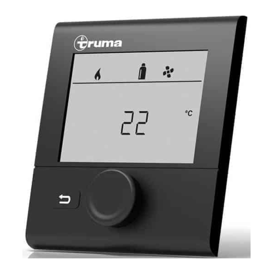
Digital control panel
Operating instructions
Installation instructions
To be kept in the vehicle.
This document is part of the product.
4010007
FIRE OR EXPLOSION HAZARD
Failure to follow safety warnings exactly
Page
2
could result in serious injury, death or prop-
Page
16
erty damage.
Do not store or use gasoline or other flam-
mable vapors and liquids in the vicinity of
this or any other appliance.
WHAT TO DO IF YOU SMELL GAS
• Evacuate all persons from the vehicle.
• Shut off the gas supply at the gas contain-
er or source.
• Do not touch any electrical switch or use
any phone or radio in the vehicle.
• Do not start the vehicle's engine or electric
generator.
• Contact the nearest gas supplier or certi-
fied service technician for repairs.
• If you cannot reach a gas supplier or certi-
fied service technician, contact the nearest
fire department.
• Do not turn on the gas supply until gas
leaks have been repaired.
Installation and service must be performed
by a certified service technician, service
agency, or the gas supplier.
Advertisement
Table of Contents
Troubleshooting

Related Manuals for Truma CP plus VarioHeat


Summary of Contents for Truma CP plus VarioHeat
- Page 1 Truma CP plus VarioHeat Digital control panel FIRE OR EXPLOSION HAZARD Operating instructions Failure to follow safety warnings exactly Page Installation instructions could result in serious injury, death or prop- Page erty damage. To be kept in the vehicle. This document is part of the product.
-
Page 2: Table Of Contents
Safety Definitions ..............3 Trademark information Safety Behavior and Practices ..........3 Operating Instructions Truma CP plus VarioHeat reffered to as CP plus VarioHeat below. Display and Operating Elements ........4 Truma AquaGo reffered to as AquaGo below. Description ................4 Rotary push button .............. -
Page 3: Consumer Safety Information
Consumer Safety Information Safety Definitions This is the safety alert symbol. This symbol alerts you to potential hazards that can kill or hurt you and others. indicates a hazardous situation which, if not avoided, could result in death or serious injury. is used to address practices not re- lated to physical injury. -
Page 4: Operating Instructions
Operating Instructions Display and Operating Elements Rotary push button The rotary push button (8) is used to select and change setpoints and parameters; it is then tapped to save the values. Selected menu items flash. Turn clockwise • The menu is scrolled through from left to right •... -
Page 5: Initial Start-Up
• The display alternates between the cur- take a few minutes due to internal time rent time and the room temperature lags of the VarioHeat or the Truma AquaGo that you set. (“OFF” is displayed during this time). • Special displays on command via CI-BUS (refer to “Special displays”... -
Page 6: Selecting The Fan Speed
Heater (HEATER) Icon Operating Description mode – Fan is switched off. (Can be selected Fig. 4 only if no appliance is running.) Heater (HEATER) Adjustable temperature range 40 – 86 °F VENT Circulating air, if no (1 °F increments) or 5 – 30 °C (1 °C increments) appliance is running. -
Page 7: Change Hot Water Mode
ANTIFR Prevention of freezing us- Change hot water mode ing 12 VDC electricity: 1. Use the rotary push button to select the icon Operating mode with in the menu line (Fig. 6 – 3). installed electric anti- 2. Tap the rotary push button to go to the set- freeze kit (available as an ting level. - Page 8 Set the room temperature 1. Depending on the connected appliance, use Fig. 13 the rotary push button to choose between heater or Truma AquaGo. 2. Tap the rotary push button to confirm the The time switch remains enabled, even for selection.
-
Page 9: Set Clock
With 100% calcification, the warning Set clock “CLEAN” is displayed in the Hot wa- ter mode menu (see “Change hot water Display 24 h mode Display 12 h mode mode” page 7) and the AquaGo must be decalcified. 2.2 CLEAN (Only AquaGo comfort / AquaGo comfort plus.) Irritation of skin and eyes in = a. -
Page 10: Special Displays
3. °C / °F temperature display Example: Select temperature display °C (Celsius) or H 1.20.01 –> H = appliance; °F (Fahrenheit). 1.20.01 = Version number Appliance P = CP plus VarioHeat control panel H = VarioHeat W = AquaGo Fig. 18 Fig. 22 8. -
Page 11: Warning / Error
= VarioHeat = AquaGo Fig. 26 Malfunction In the event of an error, the Truma CP plus Var- ioHeat control panel immediately jumps to the Fig. 24 “Warning / Error” menu level and displays the respective fault code. The cause of the error can be determined and remedied with the aid of the troubleshooting guide (from page 37 and ff). -
Page 12: Maintenance
Maintenance Technical data This control panel is maintenance-free. Display To clean the front, you can use a non-abrasive LCD, monochrome, with backlighting cloth moistened with water (and a neutral soap Diagonal 3.3 in. (84 mm) solution). Dimensions (L x W x H) 3.62 x 4.06 x 1.58 in. -
Page 13: Troubleshooting Chart Varioheat (H)
If these measures do not remedy the malfunction or if error codes are displayed that you cannot find in the troubleshooting chart, contact your dealership, Truma Service 1-855- 558-7862 or one of our authorized Service Partners. -
Page 14: Troubleshooting Chart Aquago (W)
Troubleshooting chart AquaGo (W) Error code Potential cause Solution E 1 W Flame not detected There is a flame-detection error at the burner be- cause the flame was not detected after release of gas and ignition. Important: The system indicates this error only after three attempts at intervals of approximately 30 seconds. - Page 15 Current in the antifreeze kit too high (e.g. short circuit). If these measures do not remedy the malfunction or if error codes are displayed that you cannot find in the troubleshooting chart, contact your dealership, Truma Service 1-855- 558-7862 or one of our authorized Service Partners.
-
Page 16: Installation Instructions
VarioHeat and/or AquaGo with a connector cable (TIN bus). Safety Information Dimensions • Installation and Service must be performed by an authorized Truma recommended 0.35 in. 3.62 in. (92 mm) installer, service agency or OEM. Improper (9 mm) -
Page 17: Wiring Diagram
Wiring diagram In installation situations where the back of the CP plus VarioHeat is freely accessible, the CP plus cover (contact safety device), which is available as an accessory, may be used. TIN-Bus RJ-12 female VarioHeat AquaGo 12 VDC Fig. 30 – Rear view If any of the original wire as supplied with the appliance must be replaced, it must be replaced with wire AWG# 18 - 105 °C - UL1015... -
Page 18: Installation
Installation • Mount the control panel frame on to the wall with 4 screws. Ø Maximum 0.134 in. (3.5 mm) Fig. 32 – Front view • Hook the top of the control panel into the frame via 2 latches. • Fix the top of the control panel in place with a screw (supplied). - Page 20 In case you encounter any problems, please contact the Truma Service Center at 855-558-7862 or one of our authorized service partners. For details see www.truma.net. Please have the model number and serial number (on furnace’s type plate) handy when you call.
Need help?
Do you have a question about the CP plus VarioHeat and is the answer not in the manual?
Questions and answers
We are getting error code E. 3 H. Can’t find it in the manual.