Truma CP plus Operating Instructions Manual
Hide thumbs
Also See for CP plus:
- User manual ,
- Operating instructions manual (96 pages) ,
- Installation instructions manual (32 pages)
Table of Contents
Advertisement
Available languages
Available languages
Truma CP plus
Gebrauchsanweisung
Einbauanweisung
Im Fahrzeug mitzuführen!
Operating instructions
Installation instructions
To be kept in the vehicle!
Mode d'emploi
Instructions de montage
À garder dans le véhicule !
Istruzioni per l'uso
Istruzioni di montaggio
Da tenere nel veicolo!
Seite
2
Seite 16
Page 19
Page 33
Page 36
Page 50
Pagina 53
Pagina 67
Page 71
TR
Advertisement
Chapters
Table of Contents
Troubleshooting

Related Manuals for Truma CP plus


Summary of Contents for Truma CP plus
- Page 1 Truma CP plus Gebrauchsanweisung Seite Einbauanweisung Seite 16 Im Fahrzeug mitzuführen! Operating instructions Page 19 Installation instructions Page 33 To be kept in the vehicle! Mode d‘emploi Page 36 Instructions de montage Page 50 À garder dans le véhicule ! Istruzioni per l‘uso...
-
Page 2: Table Of Contents
Bedienteil Truma CP plus Inhaltsverzeichnis Gebrauchsanweisung Einbauanweisung Sicherheitshinweise ............16 Verwendete Symbole ............3 Verwendungszweck ............3 Lieferumfang ............... 16 Sicherheitshinweise ............3 Beschreibung ..............16 Wichtige Hinweise ............3 Abmessungen ..............17 Anzeige- / und Bedienelemente ........4 Platzwahl ................17 Dreh- / Drückknopf ............... -
Page 3: Gebrauchsanweisung
Verwendungszweck – Bei Anschluss der Heizung Combi CP plus ready an das Das Bedienteil Truma CP plus dient zum Steuern und Bedienteil Truma CP plus kann die Heizung nicht mehr über Überwachen einer Heizung Combi CP plus ready und / oder eine Zeitschaltuhr ZUCB geschaltet werden. einem Truma Klimasystem. Folgende Klimasysteme können –... -
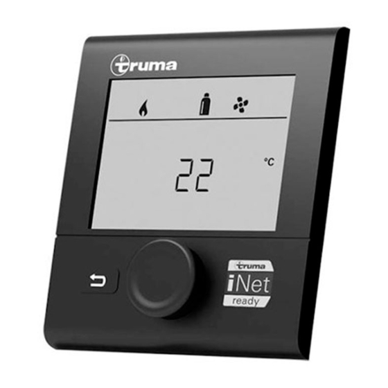
Page 4: Anzeige- / Und Bedienelemente
Anzeige- / und Bedienelemente Dreh- / Drückknopf Mit dem Dreh-/Drückknopf (8) können Sollwerte und Parame- ter angewählt, geändert und durch Antippen gespeichert wer- den. Angewählte Menüpunkte blinken. Drehen nach rechts (+) – Menü wird von links nach rechts durchlaufen. – Erhöhen von Werten. Drehen nach links (-) –... -
Page 5: Erstinbetriebnahme
Erstinbetriebnahme Funktionen Führen Sie zur Erstinbetriebnahme des Systems folgende Die Funktionen in den Menüzeilen (3, 4) des Bedienteils sind Schritte durch: in beliebiger Reihenfolge anwählbar. Die Betriebsparameter – Stellen Sie die Spannungsversorgung aller Geräte sicher werden in der Statuszeile (2) bzw. in den Anzeigen (5, 6) 12 V Gleichspannung bzw. -
Page 6: Raumtemperatur Ändern
Raumtemperatur ändern Warmwasserstufe ändern – Mit Dreh- / Drückknopf das Symbol in Menüzeile (3) anwählen. – Mit Dreh- / Drückknopf das Symbol in Menüzeile (3) anwählen. – Durch Antippen in die Einstellebene wechseln. – Durch Antippen in die Einstellebene wechseln. –... -
Page 7: Energieart Wählen
Besonderheiten im Mischbetrieb Energieart wählen Unterbrechung der Spannungsversorgung 230 V: Die Heizung schaltet automatisch in den Gas- bzw. Dieselbe- – Mit Dreh- / Drückknopf das Symbol in Menüzeile (3) anwählen. trieb. Sobald die Spannungsversorgung 230 V wieder herge- – Durch Antippen in die Einstellebene wechseln. stellt ist, schaltet die Heizung automatisch in den Mischbe- –... -
Page 8: Gebläsestufe Wählen
* Kann zu höherem Motorverschleiß führen, je nach Häufig- Gebläsestufe wählen keit der Benutzung. ** Gebläsestufe „HIGH“ ist mit höherer Stromaufnahme, höherem Geräuschpegel und erhöhtem Motorverschleiß Bei angeschlossener Heizung / Klimasystem verbunden. – Mit Dreh- / Drückknopf das Symbol in Menüzeile (3) anwählen. Sobald die Heizung eingeschaltet wird (Raumtempera- –... - Page 9 Startzeitpunkt eingeben Raumtemperatur einstellen – Mit Dreh- / Drückknopf die Stunden, anschließend die – Je nach angeschlossenem Gerät mit Dreh- / Drückknopf Minuten einstellen. zwischen Heizung oder Klimasystem wählen. – Dreh- / Drückknopf zum Bestätigen der Auwahl antippen. – Mit Dreh- / Drückknopf gewünschte Raumtemperatur wählen. –...
-
Page 10: Beleuchtung Ein-/Ausschalten
Gebläsestufe wählen Zeitschaltuhr deaktivieren (OFF) – Mit Dreh- / Drückknopf gewünschte Gebläsestufe wählen. – Durch Antippen in die Einstellebene wechseln. – Dreh- / Drückknopf zum Bestätigen des Wertes antippen. – Mit Dreh- / Drückknopf Zeitschaltuhr deaktivieren (OFF) – Dreh- / Drückknopf zum Bestätigen des Wertes antippen. Das Menü... -
Page 11: Uhrzeit Einstellen
Hintergrundbeleuchtung des Bedienteils ändern Uhrzeit einstellen Die Hintergrundbeleuchtung ist in 10 Stufen änderbar. Sprache ändern – Die Stundenanzeige blinkt. – Mit Dreh- / Drückknopf die Stunden (24 h - Modus) einstellen. Die gewünschte Sprache aus den verfügbaren Sprachen aus- – Nach erneutem Antippen des Dreh- / Drückknopf blinkt die wählen (z. -
Page 12: Anzeige Netzspannung 230 V
Auf Werkseinstellung rücksetzen (RESET) Warnung Die Reset-Funktion setzt das Bedienteil auf die Werkseinstel- lung zurück. Alle Einstellungen werden damit gelöscht. Neu angeschlossene Geräte werden im Bedienteil hinterlegt. Bei einer Warnung erscheint ein Warnsymbol, um zu sig- nalisieren, dass ein Betriebsparameter einen undefinier- Reset durchführen ten Zustand erreicht hat. -
Page 13: Störung
Technische Daten In diesem Fall ist die Warnung im Bedienteil nicht quittiert und das Warnsymbol bleibt bestehen. Das Display Bedienteil bleibt im Zustand Warnung. Weitere angeschlosse- LCD, monochrom, mit ne Geräte können bedient werden. Hintergrundbeleuchtung Abmessungen (L x B x H) 92 x 103 x 40 mm Betriebstemperaturbereich -25 °C bis +60 °C Störung... -
Page 14: Fehlersuchanleitung (Heizung Combi Gas)
– Keine Verbindung zwischen Heizung und Bedienteil – Wenden Sie sich bitte an den Truma Service. – Bedienteilkabel defekt Sollten diese Maßnahmen nicht zur Störungsbehebung führen, oder Fehlercodes angezeigt werden, die Sie nicht in der Fehlersuchanleitung finden, wenden Sie sich bitte an den Truma Service. -
Page 15: Fehlersuchanleitung (Heizung Combi Diesel)
– Sparsam mit der elektrischen Energie aus der Batterie umgehen, z. B. Beleuchtung einschränken. – Batterie laden. Sollten diese Maßnahmen nicht zur Störungsbehebung führen, oder Fehlercodes angezeigt werden, die Sie nicht in der Fehlersuchanleitung finden, wenden Sie sich bitte an den Truma Service. -
Page 16: Konformitätserklärung
Konformitätserklärung Einbauanweisung 1. Stammdaten des Herstellers Sicherheitshinweise Name: Truma Gerätetechnik GmbH & Co. KG Anschrift: Wernher-von-Braun-Str. 12, D-85640 Putzbrunn Der Einbau in Fahrzeuge muss den techni- schen und administrativen Bestimmungen 2. Identifikation des Gerätes des jeweiligen Verwendungslandes ent- sprechen (z. B. EN 1648, VDE 0100-721). -
Page 17: Platzwahl
Abmessungen Platzwahl Das Bedienteil an einer vor Feuchtigkeit und Nässe geschütz- ten Stelle einbauen. Für eine optimale Lesbarkeit der Zeichen, das Display auf Augenhöhe montieren. – Einbauöffnung für das Display herstellen. 3±1 11,5 11,5 Maße in mm Maße in mm... -
Page 18: Anschluss
Anschluss – Bedienteiloberteil über 2 Rastnasen in den Rahmen einhaken. – Bedienteiloberteil mit einer Schraube fixieren. – Dreh- / Drückknopf auf die Achse aufschieben. ESD-Vorschriften beachten! – Das Kabel (TIN-Bus) am Display anstecken und zur Heizung (zum Klimasystem) verlegen. – Das 12 V-Anschlusskabel anstecken und mit ungeschalteter 12 V Betriebsspannung verbinden (Dauerplus). - Page 19 Control panel Truma CP plus Table of Contents Operating instructions Installation instructions Safety instructions ............50 Symbols used ..............37 Intended use ..............37 Scope of delivery ..............50 Safety instructions ............37 Description ................50 Important notes ..............37 Dimensions ................51 Display and controls ............
-
Page 20: Operating Instructions
Important notes Intended use If the power supply to the system has been interrupted, the The Truma CP plus control panel is used to control and time must be re-entered. monitor a Combi CP plus ready heating system and/or a Truma air conditioning system. The following air conditioning –... -
Page 21: Display And Controls
Display and controls Rotary push button Setpoints and parameters can be selected, modified and saved by tapping on them using the rotary push button (8). Selected menu items flash. Rotate right (+) – Menu is run through from left to right. –... -
Page 22: Initial Start-Up
Initial start-up Functions In order to perform the initial start-up, the following steps are The functions in the menu bars (3, 4) of the control panel are required: selectable in any order. The operating parameters are shown – Make sure that all equipment is connected to the power supply on the status bar (2) and on the displays (5, 6). -
Page 23: Change Room Temperature
Change room temperature Change hot water level – Select icon in menu bar (3) with rotary push button. – Select icon in menu bar (3) with rotary push button. – Change by tapping in the setting level. – Change by tapping in the setting level. –... -
Page 24: Select Energy Source
Special features in mixed mode Select energy source Interruption of the mains voltage 230 V: The heating system switches automatically into gas and diesel – Select icon in menu bar (3) with rotary push button. mode. As soon as the 230 V power supply has been restored, –... -
Page 25: Select Fan Level
* Can lead to additional motor wear depending on frequency Select fan level of use. ** Fan level “HIGH” results in higher power consumption, higher noise level and increased motor wear. With connected heating / air conditioning system As soon as the heating system is switched on (room –... - Page 26 Enter start time Set room temperature – Set the hours then the minutes with the rotary push button. – Select heating or air conditioning system using the rotary push button, depending on the unit that is connected. – Tap rotary push button to confirm selection. –...
-
Page 27: Switch Lighting On/Off
Select fan level Deactivate time switch (OFF) – Select desired fan level with rotary push button. – Change by tapping in the setting level. – Tap rotary push button to confirm value. – Deactivate time switch with rotary push button (OFF) –... -
Page 28: Set Time
Change control panel background lighting Set time The background lighting has 10 different levels. Change language – The hour display flashes. – Set the hours (24h mode) with rotary push button. Select the required language from the languages available – The minutes display flashes when the rotary push button is (e.g. -
Page 29: 230 V Mains Power Supply Indicator
Reset to factory settings (RESET) Warning The reset function resets the control panel back to the factory settings. All settings will be deleted. New units that have been connected are stored in the control panel. In the event of a warning a warning symbol appears in order to signal that an operating parameter has reached an unde- Perform Reset fined condition. -
Page 30: Fault
Technical data In this case the warning is not acknowledged in the con- trol panel, and the warning symbol remains. The control Display panel remains in warning status. Other connected devices can LCD, monochrome, with be operated. background lighting Dimensions (L x W x H) 92 x 103 x 40 mm Operating temperature range -25 °C to +60 °C Fault... -
Page 31: Troubleshooting Guide (Combi Gas Heating System)
– Circulated air intake blocked – Remove blockage from circulated air intake # 21 – Room temperature sensor or cable defective – Please contact Truma Service. # 24 – Risk of low voltage – Charge battery Battery voltage too low <... -
Page 32: Troubleshooting Guide (Combi Diesel Heating System)
Rectification # 111 – Room temperature sensor or cable defective – Please contact Truma Service. # 122 – Lack of fuel due to insufficient fuel tank filling, – Fill tank with fuel. Then fill fuel line as described in “Initial startup”... -
Page 33: Declaration Of Conformity
Declaration of conformity Installation instructions 1. Information about the manufacturer Safety instructions Name: Truma Gerätetechnik GmbH & Co. KG Address: Wernher-von-Braun-Str. 12, D-85640 Putzbrunn In-vehicle installations must comply with the technical and administrative regula- 2. Device identification tions of the respective country of use (e.g. -
Page 34: Selecting A Location
Dimensions Selecting a location Install control panel in a location that is protected from mois- ture and humidity. Mount display at eye level for optimum character legibility. – Make an installation opening for the display. 3±1 11,5 11,5 The dimensions are in mm The dimensions are in mm... -
Page 35: Connection
Connection – Hook control panel upper section into frame using 2 latch- ing lugs. – Fix control panel upper section in position with a screw. Please pay attention to the ESD regulations! – Slide rotary push button onto axis. – Attach cable (TIN bus) to display and route to heating sys- tem (to air conditioning system). - Page 36 Pièce de commande Truma CP plus Table des matières Mode d’emploi Instructions de recherche de pannes (chauffage Combi Diesel) ..........32 Déclaration de conformité ..........33 Symboles utilisés ..............20 Utilisation ................20 Informations concernant la sécurité ......20 Remarques importantes ..........20 Instructions de montage Éléments d’affichage et de commande ......
-
Page 37: Mode D'emploi
– Aventa eco – En cas de raccordement du chauffage Combi CP plus ready – Aventa comfort à la pièce de commande Truma CP plus, le chauffage ne peut plus être commuté via une minuterie ZUCB. * pas en combinaison avec le convertisseur TG 1000_sinus –... -
Page 38: Éléments D'affichage Et De Commande
– Utiliser seulement la minuterie de la pièce de commande L’affichage se fait via un afficheur (1) rétro-éclairé. La touche pour déterminer de manière univoque l’heure de début et de retour (9) permet de retourner d’un menu. de fin d’une période souhaitée. Bouton rotatif/poussoir Éléments d’affichage et de commande Le bouton rotatif/poussoir (8) permet de sélectionner des... -
Page 39: Première Mise En Service
Première mise en service Fonctions Effectuez les étapes suivantes pour la première mise en Les fonctions dans les lignes de menu (3, 4) de la pièce de service du système : commande sont sélectionnables dans n’importe quel ordre. – Assurez l’alimentation en tension de tous les appareils. Les paramètres de fonctionnement sont représentés dans la Tension continue 12 V ou 230 V de tension secteur en cas ligne d’état (2) et dans les affichages (5, 6). -
Page 40: Modifier La Température Ambiante
c = AUTO – Le système de climatisation est en mode Modifier la température ambiante automatique d = HOT – Le système de climatisation est en mode de chauffage – Avec le bouton rotatif/poussoir, sélectionner le symbole e = VENT –... -
Page 41: Sélectionner Type D'énergie
* Ce symbole clignote tant que la température de l’eau sou- Symbole Mode de fonc- Type d’énergie tionnement haitée n’est pas atteinte. Gaz / diesel Gaz / diesel ** La température d’eau chaude de 40 °C peut être maintenue à 40 °C en cas de réchauffement combiné de la pièce et de EL 1 Électricité... -
Page 42: Sélectionner Palier De Ventilateur
BOOST Chauffage de pièce rapide Sélectionner palier de ventilateur Disponible si la différence entre la température ambiante choi- sie et la température ambiante En cas de chauffage/système de climatisation raccordé actuelle est >10 °C. – Avec le bouton rotatif/poussoir, sélectionner le symbole dans * Peut provoquer une usure accrue du moteur selon la la ligne de menu (3). - Page 43 – En cas de fonctionnement de systèmes de climati- Régler la température ambiante sation, utiliser seulement la minuterie de la pièce de – Selon l’appareil raccordé, choisir entre le chauffage ou le commande afin de fixer de manière univoque l’heure système de climatisation à...
-
Page 44: Allumer/Éteindre L'éclairage
Le menu de choix de type d’énergie s’affiche si un Désactiver la minuterie (OFF) chauffage équipé de thermoplongeurs électriques est – Passer au niveau de réglage en appuyant. raccordé. – Désactiver la minuterie avec le bouton rotatif/poussoir (OFF) – Appuyer sur le bouton rotatif/poussoir pour confirmer la valeur. Sélectionner palier de ventilateur –... -
Page 45: Régler L'heure
Modifier le rétro-éclairage de la pièce de commande Régler l’heure Le rétro-éclairage est modifiable en 10 paliers. Modifier la langue – L’affichage des heures clignote. – Régler les heures (mode 24 h) avec le bouton rotatif/ Sélectionner la langue souhaitée à partir des langues poussoir. -
Page 46: Affichage Tension Secteur 230 V
Réinitialiser sur le réglage d’usine (RESET) Avertissement La fonction de reset réinitialise la pièce de commande sur le réglage d’usine. Tous les réglages seront ainsi supprimés. Les appareils nouvellement raccordés sont enregistrés dans la En cas d’avertissement, un symbole d’avertissement apparaît pièce de commande. -
Page 47: Panne
Caractéristiques techniques Dans ce cas, l’avertissement dans la pièce de com- mande n’est pas acquitté et le symbole d’avertissement Afficheur reste. La pièce de commande reste dans l’état d’avertisse- LCD, monochrome, ment. D’autres appareils raccordés peuvent être utilisés. avec rétro-éclairage Dimensions (L x l x H) 92 x 103 x 40 mm Plage de températures Panne... -
Page 48: Instructions De Recherche De Pannes (Chauffage Combi Gas)
– Câble pièce de commande défectueux Si ces démarches ne permettent pas d’éliminer la défaillance, ou si des codes d’erreur que vous ne trouvez pas dans les instructions de recherche de pannes s’affichent, veuillez vous adresser au centre de SAV Truma. -
Page 49: Instructions De Recherche De Pannes (Chauffage Combi Diesel)
– Charger la batterie. Si ces démarches ne permettent pas d’éliminer la défaillance, ou si des codes d’erreur que vous ne trouvez pas dans les instructions de recherche de pannes s’affichent, veuillez vous adresser au centre de SAV Truma. -
Page 50: Déclaration De Conformité
Instructions de montage 1. Principales données relatives au fabricant Informations concernant la sécurité Nom : Truma Gerätetechnik GmbH & Co. KG Adresse : Wernher-von-Braun-Str.12, D-85640 Putzbrunn Le montage dans des véhicules doit répondre aux dispositions techniques et 2. Identification de l’appareil administratives du pays d’utilisation respec-... -
Page 51: Choix De L'emplacement
Dimensions Choix de l’emplacement Monter la pièce de commande sur un endroit sec et protégé contre l’humidité. Pour une lisibilité optimale des caractères, monter l’affi- cheur à hauteur des yeux. – Créer ouverture de montage pour l’afficheur. 3±1 11,5 11,5 Dimensions en mm Dimensions en mm... -
Page 52: Raccordement
Raccordement – Accrocher la partie supérieure de pièce de commande au cadre avec 2 becs de retenue. – Fixer la partie supérieure de pièce de commande avec une vis. Respecter les prescriptions ESD. – Pousser le bouton rotatif/poussoir sur l’axe. –... - Page 53 Unità di comando Truma CP plus Indice Istruzioni per l'uso Istruzioni per la ricerca degli errori (stufa Combi Diesel) ............66 Dichiarazione di conformità ..........67 Simboli utilizzati ..............54 Scopo d’impiego ............... 54 Avvertenze di sicurezza ........... 54 Avvertenze importanti ............. 54 Istruzioni di montaggio Elementi del display e di comando ........
-
Page 54: Istruzioni Per L'uso
Il – Anche dopo aver collegato l'unità di comando «giunto per cavo unità di comando» (n° art. 40090-69300) Truma CP plus è a disposizione il telecomando IR per il va ordinato separatamente. comando del sistema di condizionamento. L'unità di coman- do riconosce tutte le impostazioni che vengono effettuate L'apparecchio è... -
Page 55: Elementi Del Display E Di Comando
– Per stabilire chiaramente l'ora di inizio e fine di un periodo Con la manopola/il pulsante (8) è possibile selezionare i menu a scelta, è possibile utilizzare solo il temporizzatore dell'uni- nelle righe (3 + 4) ed effettuare le impostazioni. L'indicazio- tà... -
Page 56: Prima Messa In Funzione
Prima messa in funzione Funzioni Per la prima messa in funzione del sistema, eseguire le Le funzioni nelle righe del menu (3, 4) dell'unità di comando seguenti operazioni: possono essere selezionate nella sequenza desiderata. I para- – Assicurare l'alimentazione di tensione di tutti gli apparecchi metri di esercizio vengono visualizzati nella riga dello stato (2) tensione continua a 12 V o o nelle indicazioni (5, 6). -
Page 57: Modifica Della Temperatura Ambiente
d = HOT – il sistema di condizionamento è in esercizio di Modifica della temperatura ambiente riscaldamento e = VENT – il sistema di condizionamento è in esercizio di circolazione – Selezionare il simbolo nella riga del menu (3) con la mano- pola / il pulsante. -
Page 58: Selezione Del Tipo Di Energia
** La temperatura dell'acqua calda a 40 °C può essere mante- Appena viene accesa la stufa (temperatura ambiente, nuta a 40 °C solo per un tempo limitato quando il riscalda- livello acqua calda attivi), nella riga dello stato viene mento dell'acqua è combinato a quello dell'ambiente. visualizzato il tipo di energia selezionato nella procedura di Non disponibile nella variante per l'Australia. -
Page 59: Selezione Della Velocità Del Ventilatore
Selezione della velocità del BOOST Riscaldamento veloce dell'am- biente ventilatore Disponibile se la differenza tra la temperatura ambiente selezio- Con stufa / sistema di condizionamento collegata/o nata e attuale è >10 °C. – Selezionare il simbolo nella riga del menu (3) con la mano- * Può... - Page 60 – Quando sono in esercizio i sistemi di condizionamen- Impostazione della temperatura ambiente to, utilizzare solo il temporizzatore dell'unità di coman- – A seconda dell'apparecchio collegato, scegliere tra stufa o do per determinare chiaramente l'ora di avvio e fine di sistema di condizionamento con la manopola / il pulsante.
-
Page 61: Accensione/Spegnimento Dell'illuminazione
Selezione della velocità del ventilatore Disattivazione del temporizzatore (OFF) – Scegliere la velocità del ventilatore desiderata con la mano- – Passare al livello di impostazione toccando. pola / il pulsante. – Disattivare il temporizzatore (OFF) con la manopola / il –... -
Page 62: Impostazione Dell'ora
Modifica della retroilluminazione dell'unità di comando Impostazione dell'ora La retroilluminazione può essere modificata su 10 livelli. Modifica della lingua – L'indicazione dell'ora lampeggia. – Impostare le ore (modalità 24 h) con la manopola / il pulsante. Selezionare la lingua desiderata tra le lingue disponibili (ad es. –... -
Page 63: Indicazione Tensione Di Rete Di 230 V
Ripristino dell'impostazione di fabbrica (RESET) Avvertenza La funzione reset ripristina l'unità di comando all'impostazio- ne di fabbrica. In tal modo vengono eliminate tutte le imposta- zioni. Eventuali nuovi apparecchi vengono memorizzati nell'u- Con le avvertenze compare un simbolo di avvertenza che nità... -
Page 64: Guasto
Specifiche tecniche In tal caso l'avvertenza nell'unità di comando non è con- fermata e il simbolo di avvertenza rimane. L'unità di Display comando resta nello stato di avvertenza. È possibile coman- LCD, monocromo, dare gli altri apparecchi collegati. retroilluminato Dimensioni (L x P x H) 92 x 103 x 40 mm Range temperatura di Guasto... -
Page 65: Istruzioni Per La Ricerca Degli Errori (Stufa Combi Gas)
– Rivolgersi al servizio di assistenza Truma. – Cavo dell'unità di comando difettoso Qualora queste misure non consentano di eliminare l'anomalia o nel caso in cui vengano visualizzati codici di errore non descritti nelle istruzioni per la ricerca degli errori, rivolgersi al servizio di assistenza Truma. -
Page 66: Istruzioni Per La Ricerca Degli Errori (Stufa Combi Diesel)
– Caricare la batteria. Qualora queste misure non consentano di eliminare l'anomalia o nel caso in cui vengano visualizzati codici di errore non descritti nelle istruzioni per la ricerca degli errori, rivolgersi al servizio di assistenza Truma. -
Page 67: Dichiarazione Di Conformità
Dichiarazione di conformità Istruzioni di montaggio 1. Ragione sociale del costruttore Avvertenze di sicurezza Nome: Truma Gerätetechnik GmbH & Co. KG Indirizzo: Wernher-von-Braun-Str. 12, D-85640 Putzbrunn L'installazione in veicoli deve essere con- forme alle norme tecniche e amministrati- 2. Identificazione dell’apparecchio ve del rispettivo paese di utilizzo (ad es. -
Page 68: Dimensioni
Dimensioni Scelta della posizione Installare l'unità di comando in un punto protetto dall'umidità e dal bagnato. Per una leggibilità ottimale dei simboli, montare il display all’altezza degli occhi. – Creare l'apertura di montaggio per il display. 3±1 11,5 11,5 Dimensioni in mm Dimensioni in mm... -
Page 69: Collegamento
Collegamento – Agganciare la parte superiore dell'unità di comando al telaio per mezzo di 2 sporgenze ad incastro. – Fissare la parte superiore dell'unità di comando con una vite. Rispettare le norme ESD! – Spingere la manopola / il pulsante sull'asse. –... - Page 71 Truma eller Trumas serviceavdeling i landet ditt. Μπορείτε να ζητήσετε τις οδηγίες χρήσης και τοποθέτησης στη γλώσσα της χώρας σας από τον κατασκευαστή Truma ή από το σέρβις της Truma στη χώρα σας. Návod k použití a montážní návod si lze v řeči Vaší země...
- Page 72 In order to avoid delays, please have the unit model and factory number ready (see type plate). Veuillez vous adresser au centre de SAV Truma ou à un de nos partenaires de SAV agréés en cas de dysfonctionnements (consultez votre livret de service Truma ou www.truma.com).
Need help?
Do you have a question about the CP plus and is the answer not in the manual?
Questions and answers