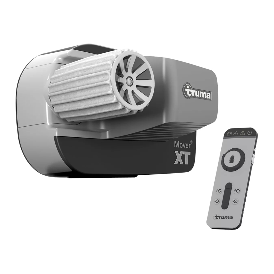
Truma Mover XT, Mover XT2 Manual
- Operating and installation instructions (100 pages) ,
- Operating instructions manual (48 pages) ,
- Information (4 pages)
Advertisement
- 1 Symbols and displays
- 2 Intended use
-
3
Product description
- 3.1 Scope of delivery
- 3.2 Accessories
- 3.3 Setup
- 3.4 Product label
- 3.5 Function
- 3.6 Power supply
-
3.7
Remote control
- 3.7.1 The remote control's functions
- 3.7.2 The remote control's symbols and acoustic signals
- 3.7.3 Switch on, normal operation
- 3.7.4 Switch on, special operation
- 3.7.5 Automatic switch off
- 3.7.6 Switch off, usual process
- 3.7.7 Switch off, special process
- 3.7.8 What to do if malfunctions occur
- 3.7.9 Replacing remote control batteries
- 3.7.10 Switching off the remote control (emergency stop)
- 4 Operation
- 5 Troubleshooting
- 6 Pairing the electronic control unit with the radio remote control
- 7 Care and maintenance
- 8 Repair
- 9 Technical data
- 10 Safety instructions
- 11 Documents / Resources
Symbols and displays
| Symbol | Meaning |
 | Warning of hazards for people |
 | Expert |
 | Additional information to help with understanding or optimising work processes. |
| • | Symbol for an action step. Something has to be done here. |
| (Fig. 3-1) | Reference to an image e.g. Figure 3 – number 1 |

Warnings are used in these operating instructions to warn against injury and property damage.
- Always read and observe warnings.
| Warning word | Meaning |
 | Hazards for people Disregard leads to death or serious injury |
| Hazards for people Disregard can lead to death or serious injury |
 | Hazards for people Disregard can lead to minor injuries |
| NOTICE | Information about preventing property damage |
The installer or vehicle owner must apply the yellow sticker with the warning information, which is enclosed with the appliance, in a location in the vehicle where it is clearly visible to all users (e.g. the wardrobe door). Missing stickers can be requested from Truma.
Abbreviations and glossary
| Word | Meaning |
| LED | Light-emitting diode |
| ABE | ABE |
Intended use
Intended use
The Mover XT is a manoeuvring system that can be used to move a caravan without the aid of the towing vehicle.
The Mover XT was designed for use on single-axle caravans with a gross weight of up to 2300 kg. The Mover XT2 is a manoeuvring system which allows a caravan to be manoeuvred without the aid of the towing vehicle.
The Mover XT2 was designed for use on dual-axle caravans with a gross weight of up to 2400 kg.
The caravan may only be manoeuvred with the manoeuvring system on campsites and private property.
Improper use
The caravan must not be manoeuvred with the manoeuvring system on public roads.
The manoeuvring system may only be used for caravans Manoeuvring of other trailers, such as boat trailers, horse box trailers, market trailers, construction trailers or similar items, is prohibited.
Installation, removal, conversion

Only competent and trained people (experts) are permitted to install and repair the Truma product and to carry out the function test, at the same time observing the installation and operating instructions and the currently recognised technical regulations. Experts are people who, based on their specialist instruction and training, their knowledge and experience with Truma products and the relevant standards, can carry out the necessary work properly and identify potential hazards.
People who are not experts should observe the following:
- Do not mount the appliance, do not install it in other locations and do not install it in other vehicles
- Do not dismantle, convert or repair the appliance yourself
- Installation, removal or conversion work may only be carried out by experts
Product description
Scope of delivery
- Manoeuvring system including radio remote control for controlling the manoeuvring system
- 20 mm spacer plate for regularly checking the gap between tyres and drive rollers
- Special spanner for manual emergency disengagement of the drive units
- If available: battery cut-off switch for establishing/disconnecting the power supply to the entire system
- Operating instructions on the functionality of the manoeuvring system with associated safety instructions
- ABE
Accessories
- PowerSet BC
Setup
Setup of the entire system
The manoeuvring system consists of two separate drive units, each with its own 12 V DC motor. These units are mounted on the frame of the vehicle in the immediate vicinity of the wheels, and are connected by a lateral bar.

- Drive unit A
- Drive unit B
- Control unit
- Battery cut-off switch
- Battery
- Charger
- Safety socket
- Remote control

- Drive unit A
- Drive unit B
- Control unit
- Battery cut-off switch
- Battery
- Charger
- Safety socket
- Remote control
Setup of the drive unit

- Drive roller
- Electric motor
- Status display engaging and disengaging
- Emergency disengaging mechanism
Setup of the power supply
Fire hazard due to the control unit being covered inside the caravan
If the control unit is inadequately ventilated, it may overheat during operation
- Adequately ventilate the control unit.
- Do not cover the control unit.
Illustration exemplary. If necessary, a second control unit, additional drive units, a safety socket or a battery cut-off switch can be provided.

- Control unit
- Manoeuvring system
- Safety socket
- Battery
- Battery cut-off switch
- Fuse
Product label
The device type and serial number are printed on the type plates.
Type plate
The type plates of the drive units are located on the left and right of the mounting tubes.
To ensure the validity of the general operating permit (ABE), the type plates must be present on the mounting tubes.

- Type plate
The type plate of the control unit is located on the underside of the control unit. The type plate of the remote control can be found in the remote control's battery compartment.
Function
Coping with inclines (max. climbing ability)
The Mover XT has been designed to cope with inclines of up to 25% bearing a gross weight of 1200 kg or 13% bearing a gross weight of 2300 kg on a suitable surface.
The Mover XT2 has been designed to cope with inclines of up to 25% bearing a gross weight of 1200 kg or 10% bearing a gross weight of 2400 kg on a suitable surface.
13% incline = 13 metre difference in altitude over a distance of 100 metres
10% slope = 10 meters difference in altitude over 100 meters distance
Once the drive rollers have been fully engaged with the tyres using remote control, the manoeuvring system is ready for operation.
Manoeuvring is carried out exclusively via the remote control, which transmits radio signals to the control unit. A separately installed 12 V lead-acid battery or suitable lead-gel battery (not supplied) provides the control unit with electrical power.
Power supply
- Always observe the operating instructions and the safety instructions prior to starting The vehicle user is responsible for correct operation of the device
Energy supply
For optimum operation, we recommend the Truma PowerSet BC and high-performance Optima® batteries. Surface-mounted batteries with a correspondingly large capacity are also suitable (see table below). Body batteries are installed in caravans with a self-sufficient power supply, for example.
Batteries
To guarantee proper operation of the manoeuvring system, it may only be operated with a charged battery (≥ 12 V).
Operation of the manoeuvring system with a charger as power source is not possible and prohibited.
Recommended battery capacities
The 12 V battery used must be certified in accordance with the national standards and regulations of the country of use and in accordance with the manufacturer's installation instructions. The battery must be dimensioned in accordance with the technical requirements of the manoeuvring system.
Starter batteries are not suitable.
Batteries with greater capacity allow the manoeuvring system to be used for longer.
| Battery type | Capacity in Ah |
| Round cell technology (Optima®) | 38 |
| Gel/AGM | 48 |
| Lead-acid battery (Liquid electrolyte) | 75 |
Fuses
The fuses used must be certified in accordance with the national standards and regulations of the country of use and in accordance with the manufacturer's installation regulations.
| Size | Value |
| Rated current | 150 A (AC/DC) |
| Voltage | 32 V |
| Colour | Pink |
| Compliant with | ISO 8820-5 (type SF 30) DIN 72581 (tripping characteristic) |
Charger
For optimum battery charging, we recommend the Truma BC 10 charger (a component of the PowerSet BC). It is suitable for all battery types and battery capacities up to 200 Ah.

Remote control
The remote control's functions
NOTICE
Damage to the remote control due to moisture or heat
- Protect the remote control from moisture
- Protect the remote control from strong sunlight
If there are other devices that transmit on the same frequency (e.g. wireless garage doors, video surveillance cameras, baby monitors, weather station, etc.) nearby, the manoeuvring system comes to an immediate standstill for safety reasons if radio frequency interference occurs. It is impossible for other radio signals to set the manoeuvring system in motion.

| Symbol | Meaning/function |
 | ON/OFF Switch on/switch off (slide switch on the side) |
 | Slide control Drive forward and in reverse |
 | Control knob Drive to the right and left |
 | Engage Drive rollers engaged |
 | Disengage Drive rollers disengaged |
The remote control's symbols and acoustic signals
| Symbol | Colour | Meaning |
 | Red | Warning – power supply/Mover battery's charging status |
 | Yellow | Short-term malfunction or warning |
 | Red | Continuous fault |
 | Green | Radio connection status |
Switch on, normal operation
| Symbol | Display | Meaning |
| Flashes slowly | After switching on the remote control, the radio connection is established (up to approx. 5 seconds) |
| Lights up continuously | Remote control and control unit are ready for operation, radio connection stable | |
| Flashes rapidly with acoustic signals | If no radio connection has been established after 10 seconds, the remote control switches off. The control unit may not be switched on or the 13-pole plug may not be inserted in the safety socket. | |
| Flashes slowly | During engage/disengage, 1x acoustic signal at the start of the procedure, 2x acoustic signal at the end of the procedure |
 | Flashing with acoustic signals | Radio connection was interrupted. Reduce the distance between the remote control and caravan (or remedy the malfunction) and switch the remote control back on again. |
Switch on, special operation
| Symbol | Display | Meaning |
| Lights up | Last engage/disengage was not fully executed: Operation is only possible when engagement/disengagement is repeated. Engage/disengage and wait for completion. |
| Flashes with acoustic signal |
Automatic switch off
No button is pressed on the remote control for some time.
| Symbol | Display | Meaning |
| Flashes rapidly with acoustic signals | The remote control switches off. |
 | Rapid flashing with acoustic signals | The remote control is switched off after a while. The warning symbol means that the drive rollers are still engaged |
Switch off, usual process
| Symbol | Display | Meaning |
| Goes out | The remote control was switched off while the control unit was still in operation and the drive rollers were disengaged. Switch off the control unit and pull out the 13-pin plug. |
Switch off, special process
| Symbol | Display | Meaning |
| Flashes with acoustic signal | Warning that the drive rollers are still engaged while the remote control is switching off. The remote control switches off after a short time. Switch the remote control back on again, disengage the drive rollers and switch off the remote control again. |
| Lights up | The control unit was switched off while the remote control was switched on. The drive rollers were disengaged during this process. The remote control switches off after a short time. Move the remote control's slide switch into the Off position. |
| Flashes with acoustic signal | |
| Lights up | The control unit was switched off while the remote control was switched on. The drive rollers were engaged during this process. The remote control switches off after a while. Switch the control unit and the remote control back on again, disengage the drive rollers and switch off normally. |
 | Flashing with acoustic signal | |
 | Flashing with acoustic signal | The 13-pin plug was pulled out of the safety socket while the remote control was switched on. The drive rollers were engaged during this process. Switch the control unit back on again by plugging in the 13-pin plug, switch the remote control off and back on again, disengage the drive rollers and switch off normally. |
| Flashes with acoustic signals | The 13-pin plug was pulled out of the safety socket while the remote control was switched on. The drive rollers were disengaged during this process. The remote control switches off after a short time. Move the remote control's slide switch into the OFF position. |
What to do if malfunctions occur
Weak battery, overcurrent, overtemperature or other malfunctions
| Symbol | Display | Meaning |
| Lights up | Lights up in the event of a temporary malfunction, and an acoustic signal is also emitted in the event of overcurrent/overtemperature. The power is automatically reduced. Allow the system to cool down. |
 | Light up | The battery charge is low, the remote control switches off after one minute with acoustic signals. Charge the battery, replace it if necessary after checking it |
| Lights up continuously with acoustic signal | Lights up in the event of a persistent fault, and an acoustic signal is also emitted, e.g. in the event of a faulty drive motor, engage the parking brake. See "Troubleshooting". |
All symbols "off" and no acoustic signal
- Manoeuvring system off (check batteries in remote control if necessary)
Replacing remote control batteries
NOTICE
Damage to the remote control due to leaking batteries
Leaking batteries can damage the remote control. Then, the manoeuvring system can no longer be used.
- Use leak-proof batteries
- If the remote control is not being used for an extended period of time, remove the batteries from the remote control
No warranty is given for damage caused by leaking batteries
Only use leak-proof micro-batteries with a steel outer casing, type LR 03, AAA, AM 4, MN 2400 (15 V). Different types of batteries or new and used batteries must not be used together.

- Slide open the battery cover
- Remove flat batteries from the remote control and dispose of safely
- Insert new batteries Note the positive and negative poles
- Close the battery cover again
The remote control switches itself off automatically after approx 3 minutes if none of the buttons are pressed
- To reactivate the remote control, set the side slide switch to OFF and after approx 4 seconds adjust it back to ON
There is no "On/Off" switch on the caravan itself
Switching off the remote control (emergency stop)
The side slide switch on the remote control (ON/OFF) also acts as an "Emergency Stop switch"
- In the event of noticeable problems, e.g. uncontrolled behaviour of the shunting system, immediately set the side slide switch to OFF
The remote control can only be switched on again if it has been switched off for at least 4 seconds. If the remote control is switched off and on again quickly, it remains switched off.
Operation
- Read and observe the safety instructions before using the manoeuvring system See "Safety instructions".
Personal injury due to the caravan behaving in an uncontrolled manner.
If the drive rollers are not completely engaged, uncontrolled changes of direction or driving movements may occur during manoeuvring
- Check that the engagement is correct on both sides See "Engage the manoeuvring system".
Personal injury due to the caravan sliding in an uncontrolled manner.
The caravan's tyres may lose grip on slippery surfaces (snow, ice, slush, wet grass)
- Watch out for uncontrolled sliding movements
- Keep a safe distance from the caravan
NOTICE
Property damage due to a lack of care and maintenance performed on the manoeuvring system
If the manoeuvring system is not kept clean and regularly maintained, dirt and lack of control of the manoeuvring system and tyres can lead to damage
- Inspect the manoeuvring system for damage before use
- Check the tyre condition and pressure
- Check the gap between the tyres and drive rollers
- Remove any foreign bodies, dirt or similar items from between the drive rollers and tyres
Uncoupling the towing vehicle
- Secure the towing vehicle against rolling away See the vehicle's operating instructions
![]()
Personal injury due to the caravan rolling away
Uncoupling from the towing vehicle can cause the caravan to roll away uncontrollably.- Apply the parking brake (Fig. 9) and/or secure the tyres with wheel chocks.
![]()
- Apply the parking brake (Fig. 9) and/or secure the tyres with wheel chocks.
- Before uncoupling, make sure that the overrun brake is released.

- Remove the 13-pin plug or adapter from the towing vehicle
- Release the breakaway cable (Fig. 10-1)
- Crank the jockey wheel out until contact with the ground (Fig. 10-3)
- Open the ball coupling (Fig. 10-2) and lift the drawbar with the jockey wheel


Switch on the manoeuvring system
Battery cut-off switch
Personal injury due to activation of the battery cut-off switch when the drive rollers are engaged
The manoeuvring system can move off in an uncontrolled manner as soon as the power supply is established due to faulty wiring or a fault in the control unit
- Only switch on the battery cut-off switch when the drive rollers are disengaged.
Procedure if there is a battery cut-off switch present:
![]()
- Insert the key into the battery cut-off switch (Fig. 11-1) Insert the lug (Fig. 11-2) into the recess (Fig. 11-3) while doing so.

- Turn the key This establishes the power supply to the manoeuvring system


Safety socket
For safety reasons, the manoeuvring system can only be operated if the caravan's 13-pin plug or adapter is plugged into the safety socket.

- If necessary, remove the 13-pin plug or adapter from the towing vehicle
- Open the lid of the safety socket and hold it open (Fig. 13-1)
- Plug the 13-pin plug or adapter into the caravan's safety socket (Fig. 13-2) The lug on the adapter must slide into the safety socket groove
- Turn the 13-pole plug or adapter one quarter of a turn in an anti-clockwise direction (Fig. 13-3) and let the cover engage on the adapter
If the 13-pin plug or adapter is pulled out of the safety socket during operation, the manoeuvring system is switched off immediately.
Switch on the remote control
NOTICE
Property damage due to uncontrolled remote control button commands
If you put the switched-on remote control into your trouser pockets, or if it is used by children, the manoeuvring system can be set in motion unintentionally.
- Always switch off the remote control once manoeuvring is complete
- Do not keep the remote control into your trouser or similar pockets
- Keep the remote control out of the reach of children
No other remote control function must be active (slide control/control knob must be in the centre position) when the remote control is switched on.

- Slide the slide switch on the side forwards (Fig. 14) After switch-on, the
![]() symbol flashes in the toolbar for approx 5 seconds. Then the
symbol flashes in the toolbar for approx 5 seconds. Then the ![]() symbol lights up continuously and the manoeuvring system is ready for operation.
symbol lights up continuously and the manoeuvring system is ready for operation.
Engage the manoeuvring system
Personal injury due to the caravan rolling away
If the parking brake is released during the engagement, the caravan can roll away in an uncontrolled manner
- Only release the caravan's parking brake when the drive rollers on both sides are completely engaged.
The drive rollers are engaged on the caravan wheels by means of the remote control.

- To engage the drive units, press and hold both buttons ATTEND
![]() simultaneously (Fig. 15) After a safety delay of 3 seconds, an acoustic signal sounds and the engagement of the drive rollers begins.
simultaneously (Fig. 15) After a safety delay of 3 seconds, an acoustic signal sounds and the engagement of the drive rollers begins. - The ENGAGE buttons
![]() can be released The
can be released The ![]() symbol flashes in the toolbar during the engagement. If the engagement is complete, two acoustic signals sound and the
symbol flashes in the toolbar during the engagement. If the engagement is complete, two acoustic signals sound and the ![]() symbol disappears from the toolbar.
symbol disappears from the toolbar.
The drive commands with the control knob and/or slide control are only executed when the drive rollers are fully swiveled. If the engagement is interrupted, it must be restarted and performed in full. Drive commands can only be executed afterwards.
If the two DISENGAGE buttons ![]() are pressed during the engagement, the engagement is immediately interrupted and the disengagement is started.
are pressed during the engagement, the engagement is immediately interrupted and the disengagement is started.
Before engagement:

Engagement:

Successful engagement:

Control of correct engagement:
- The drive rollers are pressed approx 20 mm into the tyres on both sides
- The digit 3 must be visible on the status display on the manoeuvring system


| Display | Condition |
| 1-2 | Engagement incomplete |
| 3 | Drive rollers completely engaged |
| No digit visible | Drive rollers completely disengaged |
If the drive units do not engage properly, see "Troubleshooting".
Manoeuvring the caravan
Personal injury due to collision
If persons or objects are present in the manoeuvring range during the manoeuvring, collisions and injuries may occur.
- There must not be any people or objects in the manoeuvring range
- Nobody may remain in or on the caravan
Personal injury due to uncontrolled movements of the manoeuvring system
Malfunctions in the manoeuvring system, the control unit or the remote control can lead to the caravan moving unpredictably.
- The slide switch on the side for switching off the remote control can also be used as an emergency stop switch in dangerous situations If there are noticeable problems, immediately slide the slide switch on the side to the back See "Switching off the remote control".
- Apply the caravan's parking brake.
- Switch off the battery cut-off switch.
NOTICE
Damage to the tyres due to manoeuvring with the parking brake applied
If the caravan's parking brake is not released after the engagement, the tyres may be damaged when the caravan is manoeuvred.
- Before manoeuvring, release the parking brake or remove the chocks.
When the buttons are released, or if the radio signal is interrupted or becomes too weak, the caravan immediately stops moving.
Control knob and slide control
Precise movement in all directions is possible using the control knob and the slide control. The caravan starts to move without jolting when starting.
When the control knob or slide control are released, or if the radio signal is interrupted or becomes too weak, the caravan stops moving immediately.
Radio equipment or other remote controls will not activate your manoeuvring system.
After start-up, the manoeuvring system moves at a steady speed (depending on the position of the slide control). Speed increases slightly on downhill slopes and decreases on uphill slopes.
Slide control only
The slide control can be used to drive forwards or backwards without jolting, with infinitely variable speed control. The further the slide control is moved from the zero position, the faster the speed.
Drive forward

Drive in reverse

Control knob only
The caravan symbol on the control knob indicates the current direction of travel (of the caravan).
The further the control knob is moved, the faster the caravan turns on the spot.
Continuous turning on the spot is not possible with a dual-axle chassis (XT2) due to the design. To continue turning, the caravan must be moved forwards or backwards at the same time (using the slide control).
Turn left


Turn right

Control knob and slide control
The more the control knob is turned, the smaller the turning radius. Operating the control knob and the slide control causes the manoeuvring system to go round in a circle, whereby the wheels rotate continuously, but the inner wheels rotate more slowly than the outer wheels.
Very tight bends are not possible with a dual-axle chassis due to the design.
Drive forward to the left

Driving forward on the right

Driving backward to the left

Driving backward to the right

- After manoeuvring, apply the parking brake and/or secure the caravan with chocks to prevent it from rolling away first of all, then deactivate the manoeuvring system.
Coupling to the towing vehicle
The manoeuvring system allows a caravan to be coupled to a towing vehicle with millimetre accuracy. However, this requires care and a degree of practice.
- Move the towing vehicle close to the caravan.
- Secure the towing vehicle against rolling away according to the operating instructions.
- To position the caravan precisely, operate the control knob and/or slide control until the coupling of the caravan is exactly above the ball head of the trailer coupling of the towing vehicle.

- Attach the coupling of the caravan to the ball head of the trailer coupling and snap it in securely and lock it according to the instructions for the trailer coupling ((Fig. 30-2)
- Crank in the jockey wheel and secure in accordance with the operating instructions (Fig. 30-3)
- Attach the breakaway cable (Fig. 30-1)
- Then disengage the manoeuvring system See "Disengage the manoeuvring system".

Only insert the 13-pole plug or adapter into the supply socket of the towing vehicle after the drive rollers have been disengaged.
Disengage the manoeuvring system
NOTICE
Property damage due to towing the caravan with the drive rollers engaged
If the caravan is being towed by the towing vehicle with the drive rollers engaged, the manoeuvring system, the towing vehicle or even the caravan can be damaged.
- Ensure that the drive rollers are completely disengaged before the caravan is towed by the towing vehicle.
Personal injury due to the caravan rolling away
If the drive rollers are disengaged, the caravan cannot be controlled.
- Before disengaging, apply the parking brake of the caravan and/or secure it with wheel chocks.
Pour off:
The drive rollers are disengaged on the caravan wheels by means of the remote control.
- To disengage the drive rollers, press and hold both buttons DISENGAGE
![]() simultaneously for approx 3 seconds (safety delay) until an acoustic signal sounds and the drive rollers begin to disengage.
simultaneously for approx 3 seconds (safety delay) until an acoustic signal sounds and the drive rollers begin to disengage. - During the disengagement, the
![]() symbol flashes and the DISENGAGE buttons
symbol flashes and the DISENGAGE buttons ![]() can be released. When the drive rollers' end position is reached, two acoustic signals sound and the symbol
can be released. When the drive rollers' end position is reached, two acoustic signals sound and the symbol ![]() disappears from the toolbar.
disappears from the toolbar.

If the disengagement is interrupted, this process must be restarted and performed in full.
The status display shows how far the drive rollers are engaged or disengaged:

Display Condition 1-2 Engagement incomplete 3 Drive rollers completely engaged No digit visible Drive rollers completely disengaged
 symbol flashes and the DISENGAGE buttons
  can be released. When the drive rollers' end position is reached, two acoustic signals sound and the symbol

After disengaging:

Control of correct disengagement:
- In the disengaged position, the drive rollers are approx. 20 mm away from the tyres (Fig. 33) on both sides. See "Troubleshooting" to check the correct gap between the tyres and drive rollers
- The status display no longer shows a digit (Fig. 33).
The manoeuvring system can also be disengaged manually if the power supply to the manoeuvring system is interrupted or a malfunction prevents automatic disengagement. See "Emergency disengagement".
Disengage the manoeuvring system manually
(emergency disengagement)
Personal injury due to the caravan rolling away
If the drive rollers are disengaged, the caravan cannot be controlled.
- Before disengaging, apply the parking brake of the caravan and secure it using wheel chocks.
NOTICE
Damage due to incorrect tools
The manoeuvring system may only be disengaged manually. Other auxiliary equipment, eg cordless screwdrivers, can damage the manoeuvring system.
- Use the special spanner supplied.
If the body battery is discharged to such an extent that the electric disengaging function no longer works, or if there is a defective battery, it can also be disengaged manually.

- Before manual disengagement, apply the caravan's parking brake and secure the wheels against rolling away.
- Disconnect the power supply for the manoeuvring system using the battery cut-off switch.
- Prise out the plastic cap (Fig. 34-1) at the rear end of the cover using a screwdriver.
- Place the special spanner on the hex bolt (Fig. 34-2) and carefully disengage the drive unit by turning it clockwise (Fig. 34-3)
![information]() The special spanner is included in the scope of delivery.
The special spanner is included in the scope of delivery. - Repeat the procedure for all drive units.
![information]() Once the battery has been charged or the defect remedied, the drive rollers can be engaged electrically again.
Once the battery has been charged or the defect remedied, the drive rollers can be engaged electrically again.
Switch off the manoeuvring system
NOTICE
Damage to the tyres and drive unit due to continuously engaged drive rollers.
If the manoeuvring system's drive rollers remain engaged continuously, this can cause damage to tyres and drive units if the system is at a standstill for an extended period of time.
- The drive rollers must be fully disengaged if the system is at a standstill for an extended period of time.
Switch off the remote control
- Slide the slide switch on the side downwards to switch off the remote control (Fig. 35). The green LED goes out.


Safety socket

- Turn the 13-pole plug or adapter one quarter of a turn in an anti-clockwise direction (Fig. 36-1)
- Pull the 13-pole plug or adapter out of the safety socket (Fig. 36-2)
- Then insert the 13-pin plug or adapter into the towing vehicle's 13-pin supply socket.
If the 13-pin plug is pulled out of the caravan's safety socket, even though the manoeuvring system is still engaged, the system issues a warning while the remote control is still switched on.
Battery cut-off switch
- Depending on the installation in the caravan, also disconnect the power supply for the manoeuvring system using the battery cut-off switch.

- Turn the key in an anti-clockwise direction. This interrupts the power supply to the manoeuvring system.
- Remove the key of the battery cut-off switch and keep it in a safe place that is inaccessible to children.

Troubleshooting
Before contacting the customer service, the following points should be checked:
- Check whether the batteries in the remote control are working perfectly.
- Check whether the remote control is paired with the control unit. For pairing the electronic control unit with the radio remote control, see "Pairing the electronic control unit with the radio remote control".
- Check that the caravan's 13-pin plug or adapter is properly plugged into the safety socket.
- Check that the body battery is in perfect condition and fully charged.
![information]() Battery performance can deteriorate considerably at low ambient temperatures.
Battery performance can deteriorate considerably at low ambient temperatures. - Check that the fuse in the battery connector cable is in order. If the fuse is defective, check the system for possible short circuits.
![information]() If errors occur, the remote control always switches off once the symbols have been shown.
If errors occur, the remote control always switches off once the symbols have been shown. - If these actions do not remedy the problem, please contact Truma Service
| Error | Cause and remedy |
| Manoeuvring system not working | Check the power supply (the green LED of the control unit should light up). Replace a defective fuse in the battery connection cable of the manoeuvring system only with an original Truma spare part. Interrupt the power supply for at least 20 seconds. Restore the power supply. The green LED on the control unit should be lit. |
| Manoeuvring system not working and red LED on control unit flashing | Control unit is overheated. Interrupt the power supply with the battery cut-off switch and remove the key. Allow the control unit to cool down for at least 20 minutes. Then start the manoeuvring system. |
| Manoeuvring system not working, red and green LED flashing on the control unit | Overloading of the power electronics (e.g. overloaded caravan, excessive slope). Interrupt the power supply for at least 20 seconds Restore the power supply |
| Manoeuvring system not responding to commands from remote control or only with interruptions |  Symbols flash on the remote control. Remote control's battery charge is too low |
| Manoeuvring system's battery low – green LED on control unit flashes. Check the battery of the shunting system. Charge or replace battery if necessary. | |
| Drive roller sliding off tyre | Check the tire pressure and adapting if necessary. Check the tyre tread and change the tires if necessary. Disengage the manoeuvring system and measure the gap between the tyres and drive roller. The gap must be 20 mm. |
| Manoeuvring system not disengaging | Disengage the manoeuvring system manually (see "Disengage the manoeuvring system manually") |
Pairing the electronic control unit with the radio remote control
The remote control and the control unit are paired with each other at the factory. If the control unit or the remote control is replaced, they must be paired again.
- Check the proper connection and condition of the battery. Make sure that 12 V is applied to the control unit.
The drive rollers must not be engaged.
- If necessary, disengage the drive rollers.
- Make sure that the 13-pin plug or adapter is plugged into the safety socket.
- First read the following instructions in full, as there is only a limited time window available for pairing (approx 10 seconds).
A ballpoint pen or small screwdriver, for example, is required to press the reset knob (Fig. 38-1)

Procedure:
- Switch off the remote control with the slide switch on the side (see "The remote control's functions".)
- After switching on the control unit (e.g. with the battery cut-off switch), wait (approx 15 seconds) until the red LED (Fig. 38-2) starts flashing slowly.
- Press and hold the reset knob (Fig. 38-1) on the control unit Wait until the LED (Fig. 38-2) flashes very quickly.
- Press and hold the left ENGAGE button
![]() on the remote control.
on the remote control. - Switch on the remote control with the slide switch on the side while doing so.
- Release the left ENGAGE button
![]() .
.
Once the appliances are paired, the red LED (Fig. 38-2) on the control unit and the![]() symbol on the remote control light up continuously.
symbol on the remote control light up continuously. - If pairing was unsuccessful, the red LED (Fig. 38-2) flashes and you have to repeat the process.
Care and maintenance
Cleaning and user-performed maintenance must not be carried out by children when unsupervised.
Severe to lethal injury due to short circuiting
Parts of the appliance are supplied with power over an on-board power supply consisting of 12 V batteries. In the event of high electrical loads or a short circuit, very high currents can flow through the supply lines, causing the cables to heat up and a cable fire to break out.
- Fuse cables with appropriate safety fuses.
- Cover the battery poles.
- Cover open electrical contacts.
- Use isolated plug-in connectors.
NOTICE
Damage to the manoeuvring system due to incorrect cleaning
- Do not clean the manoeuvring system with a high-pressure cleaner.
- Only use gentle detergents.
12 V battery care
Notes for handling batteries
- When handling batteries, pay attention to the manufacturer's safety instructions and data sheets.
- Ensure that the terminal clamps are secure.
- When removing the battery, first disconnect the negative terminal, followed by the positive terminal.
- When installing the battery, first connect the positive terminal, followed by the negative terminal.
- When the batteries are removed, cover the terminals with protection caps to prevent a short circuit.
Battery care (including maintenance-free batteries)
In order to achieve a long battery service life, attention must be paid to the following points:
- Batteries should be fully charged before and after removing power.
- For stationary periods of longer than 24 hours, interrupt the power circuit (e.g. using the battery cut-off switch or by disconnecting the battery poles).
- For longer stationary periods, the battery must be disconnected and charged at least every 12 weeks.
In winter, store the fully charged battery in a cool, frost-free place and recharge it regularly (every 12 weeks).
Remote control care
- Keep the remote control in a dry place.
- During long periods of inactivity (e.g. in winter), the batteries must be removed from the remote control. This prevents damage to the remote control due to leaking batteries.
Tyre care
If the caravan is parked with the drive units engaged, the tyres can get pressure marks and damage.
- Disengage the drive units when the caravan is parked.
Drive unit care
The drive units must be able to move freely and be returned automatically to the safe idle position when they are disengaged.
- If this is not the case, check the drive units for dirt or corrosion on their guides and clean them if necessary to ensure they can move properly.
- When cleaning the caravan, spray the manoeuvring system with a water hose and clean with a soft brush. Make sure that no stones, branches etc. are trapped.
Maintaining the manoeuvring system
Personal injury due to a lack of system maintenance
If the gap between the drive rollers and tyres is too large or if the tyre pressure is too low, there is a risk that the drive rollers will no longer engage completely with the necessary pressure.
- Regularly check the gap between the drive rollers and tyres using the spacer plate.
- Regularly check the caravan's tyres and the tyre pressure.
- At least every 2 years, the manoeuvring system must be checked by an expert for rust, tight fit and the proper condition of all safety-relevant parts.
The manoeuvring system is extremely easy to check or maintain during the caravan's annual inspection.
If in doubt, please contact Truma Service (www.truma.com).
Maintaining the tyres
- Before use, check the tyre pressure and that the drive rollers have the correct gap to the tyres when disengaged.
- Every time tyres are replaced, check the gap between the drive rollers and the tyres and, if necessary, have it adjusted by a specialist shop.
Check the gap between the rollers and the tyres
The gap between the tyres and drive rollers can be checked using the spacer plate. The distance must be 20 +/- 1 mm.
- Disengage the manoeuvring system.
- Slide the spacer plate between the tyre and the drive roller.
The spacer plate may just fit between the tyre and the drive roller. If the spacer has too much play and falls through between the tyre and the drive roller, the gap must be readjusted.
- Consult a specialist workshop to set the correct gap.
Standstill for an extended period of time
- Clean the manoeuvring system as described above every year (or before preparing for winter).
- In case of a longer standstill period, the battery must be disconnected. This prevents a deep discharge of the battery.
- Charge the battery before starting up.
Maintenance of the control unit
The control unit does not require any maintenance
Repair
NOTICE
Damage due to repair work being carried out by incompetent individuals
If the manoeuvring system is damaged, further damage may result if untrained individuals perform the repair work or genuine Truma spare parts are not used.
- Only have experts perform repair work on the manoeuvring system.
- Use only original Truma spare parts.
Technical data
| Mover XT manoeuvring system | |
| Size | Value |
| Area of application | Single-axle caravans with a gross weight of up to 2300 kg |
| Max. climbing ability | 13 % |
| Operating voltage | 12 V DC |
| Maximum power consumption | 150 A |
| Positive line fuse | 150 A |
| Average power consumption | 28 A |
| Quiescent current Plugged in/unplugged 13-pin connector | < 80 mA/< 150 µA |
| Maximum speed | approx. 0.17 m/s |
| Weight (not including battery) | 28 kg |
| Remote control frequency | Class 2, 868 MHz |
| Remote control battery | Micro-batteries with a steel outer casing, LR 03, AAA, AM 4, MN 2400 (1.5 V) |
| Min./max. temperature | -30°C to +45°C |
| Moisture | 0-100 % |
| Mover XT2 manoeuvring system | |
| Size | Value |
| Area of application | Dual-axle caravans with a gross weight of up to 2400 kg |
| Max. climbing ability | 10 % |
| Operating voltage | 12 V DC |
| Maximum power consumption | 150 A |
| Positive line fuse | 150 A |
| Average power consumption | 28 A |
| Quiescent current Plugged in/unplugged 13-pin connector | < 80 mA/< 150 µA |
| Maximum speed | approx. 0.17 m/s |
| Weight (not including battery) | 28 kg |
| Remote control frequency | Klasse 2, 868 MHz |
| Remote control battery | Micro-batteries with a steel outer casing, LR 03, AAA, AM 4, MN 2400 (1.5 V) |
| Min./max. temperature | -30°C bis +45°C |
| Moisture | 0-100 % |
Safety instructions
General safety
Disregarding the safety instructions and regulations may seriously endanger the health or life of persons or cause serious property damage.
- Read the safety instructions and follow them exactly
- Observe locally applicable laws, directives and standards relating to using and operating the appliance
Obligations of the operator/vehicle owner
Prerequisite for operation
Who is allowed to operate the manoeuvring system? The manoeuvring system may be operated only by persons of legal age who have been made aware of the potential risks when using the product and who are able to safely operate the manoeuvring system together with the vehicle.
Cleaning and maintenance must not be carried out by children without supervision.
Children must be supervised so that they do not play with the appliance.
Children under 3 years of age must be kept away from the appliance or supervised at all times.
- Never allow children to play with the manoeuvring system
- Never use the manoeuvring system under the influence of drugs, alcohol or medication
Condition of the tyres
In order to ensure that the manoeuvring system operates correctly, the gap between the tyres and the disengaged drive rollers must be 20 mm. All tyres must be inflated to the same pressure in accordance with manufacturer's instructions. Tyre wear or the fitting of new tyres may make it necessary to readjust the gap between the drive rollers and the tyres.
- Regularly control the distance between the drive roller and the tyre
- Regularly control the tire pressure
All wheels and tyres on the caravan must be of the same size and type In the event of disregard, safety during operation cannot be secured.
Before using the manoeuvring system for the first time, practice with it to familiarise yourself with the functions of the remote control and of the manoeuvring system.
- Inspect the manoeuvring system for damage before use. The manoeuvring system must not be used if it is damaged.
- Before each use of the manoeuvring system, check the tyres and drive rollers; remove any sharp stones and similar objects between the drive rollers and tyres.
Safe operation
Drive rollers
If the drive rollers are not completely engaged, the caravan cannot be controlled.
- Always fully engage the drive rollers.
When engaging/disengaging and during operation of the shunting system, care must be taken to ensure that no hair, parts of the body, clothing or other parts of the body can be caught by moving parts of the shunting system (e.g. drive rollers).
Never tow the caravan with the drive rollers engaged, as this may cause damage to the tyres, the towing vehicle and the drive units, as well as to accessories.
Always apply the parking brake first after manoeuvring. Then block the wheels, especially on sloping surfaces (e.g. with wheel chocks) Then disengage the drive rollers from the tyres.
The manoeuvring system is not suitable for use as a parking brake for the parked caravan.
Sloping ground
The caravan can tilting around its axle if the rear is moved downhill on slopes.
- When manoeuvring on slopes the drawbar should be pointed downwards (downhill).
Distance to the manoeuvring system
When manoeuvring, the distance between the radio remote control and the middle of the caravan must not exceed 10 m!
Due to the characteristic properties of a radio signal, it may be interrupted by terrain/objects. This reduces reception quality in small areas around the caravan, as a result of which the operation of the manoeuvring system may be briefly interrupted.
- If necessary, reduce the gap between the control unit and the remote control
- Switch the remote control off and back on again
Persons inside the caravan
- Only move caravans with a manoeuvring system when there is nobody inside
Persons outside the caravan
- No persons, especially children, may be present in the turning and movement range (manoeuvring range) of the caravan
Keeping an overview of the situation
- Ensure that there is sufficient visibility and space when manoeuvring
Switch off the manoeuvring system
After switching off the shunting system with the remote control, the control unit remains in standby mode. To completely switch it off, the battery must be disconnected or isolated from the power supply via a previously installed battery cut-off switch.
Do not put the ready-to-operate remote control in your pocket or lay it down, otherwise functions could be triggered accidentally via buttons or the control knob or slide control.
Always secure the remote control against unauthorized access. Pay particular attention to children.
General instructions relating to the manoeuvring system
When jacking up the caravan, the manoeuvring system must not be used as a support point, as this could damage the drive unit and the vehicle. The empty weight of the vehicle increases by the weight of the manoeuvring system, which reduces the payload of the vehicle.
- Do not exceed the permissible gross weight when loading the caravan
Depending on the weight of the caravan, the manoeuvring system can only overcome obstacles (e.g. kerb) from a height of approx 3 cm with auxiliary equipment (e.g. levelling ramps).
Levelling ramps must not exceed an incline of 25% (14 °)! Otherwise, depending on the weight of the vehicle, it may not be possible to overcome the incline or the tyre tread may be damaged.
- Levelling ramps or so-called tire protection systems to prevent flat-spotting often have steeper slopes and are not suitable for use with a manoeuvring system.
Sensitive objects, such as cameras, DVD players, etc., must not be stored in the stowage box near the control unit or the motor connector cable. The strong electromagnetic fields around the power cables could damage the appliances.
What to do if malfunctions occur
Emergency stop
The side slide switch on the remote control (ON/OFF) also acts as an "Emergency Stop switch" Switch the side slide switch to "OFF" immediately in case of any noticeable problems, e.g. uncontrolled behaviour of the manoeuvring system.
Documents / Resources
References
Download manual
Here you can download full pdf version of manual, it may contain additional safety instructions, warranty information, FCC rules, etc.
Advertisement


Need help?
Do you have a question about the Mover XT and is the answer not in the manual?
Questions and answers