FLUKE 381 Manual
- User manual (44 pages) ,
- Calibration manual (28 pages) ,
- Specifications (2 pages)
Advertisement
Introduction

Read "Safety Information" before you use the Meter.
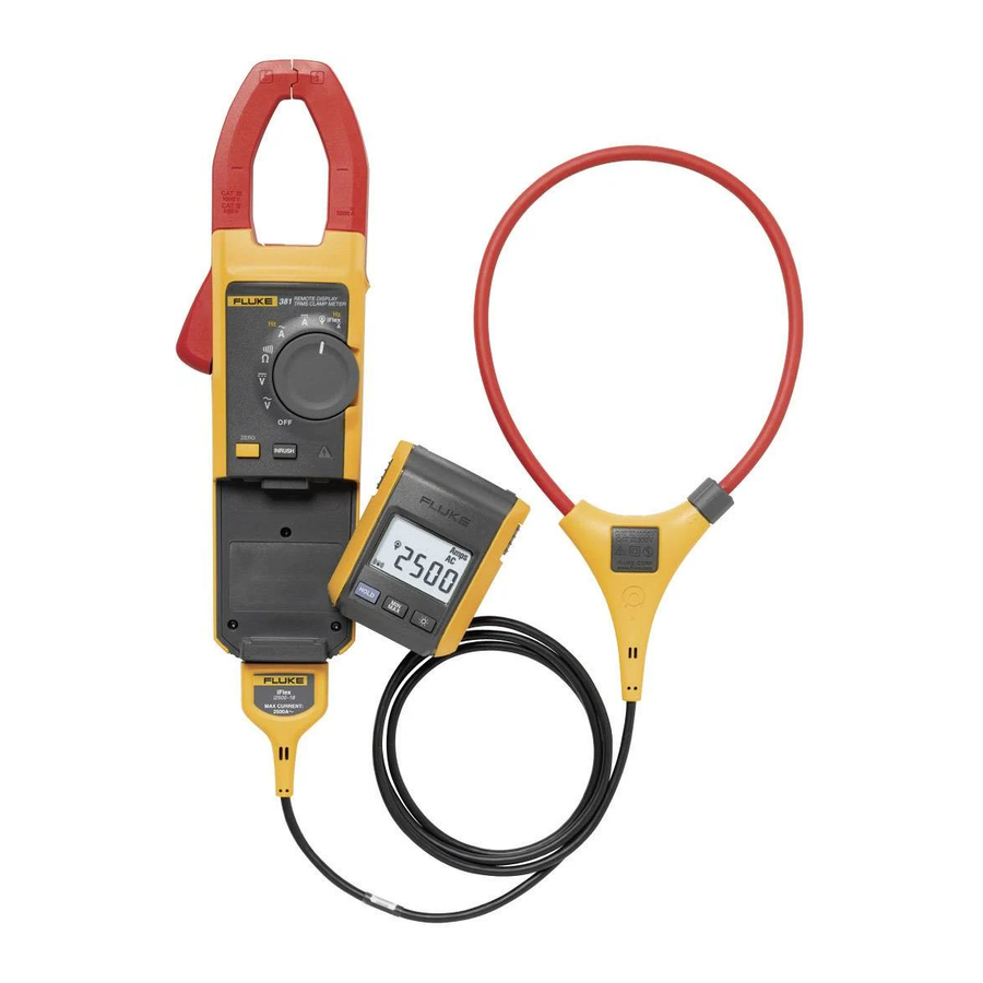
The Fluke 381 is a handheld, battery-operated Clamp Meter (the Meter) that has a remote-display module and detachable iFlex (Flexible Current Probe). The Remote Display can be removed from the Meter body and read away from the measurement source. This lets the display be easily read in difficult-measurement situations such as a hazardous environments, or very tight spaces. The Flexible Current Probe makes it possible to measure higher current (up to 2500 A ac) and larger cables that traditional jawed meters cannot measure.
How to Contact Fluke
To contact Fluke, call one of the following telephone numbers:
- Technical Support USA: 1-800-44-FLUKE (1-800-443-5853)
- Calibration/Repair USA: 1-888-99-FLUKE (1-888-993-5853)
- Canada: 1-800-36-FLUKE (1-800-363-5853)
- Europe: +31 402-675-200
- Japan: +81-3-3434-0181
Safety Information
- Examine the test leads for damaged insulation or exposed metal. Check test lead continuity. Replace damaged test leads before using the Meter.
- Do not use the Meter if it operates incorrectly. Protection can be compromised. When in doubt, have the Meter serviced.
- Do not use the Meter around explosive gas, vapor or in damp or wet environments.
- Use only type AAA batteries, properly installed in the Meter case, to power the Meter.
![shock hazard]() To avoid false readings that can lead to electrical shock and injury, replace the batteries as soon as the low battery indicator (meter
To avoid false readings that can lead to electrical shock and injury, replace the batteries as soon as the low battery indicator (meter ![]() or remote
or remote ![]() ) appears.
) appears.- When servicing the Meter, use only specified replacement parts. See Table 5.
- Have the Meter serviced only by qualified service personnel.
![]()
Be careful around voltages > 30 V ac rms, 42 V ac peak, or 60 V dc. Such voltages pose a shock hazard.- Do not apply more than the rated voltage, as marked on the Meter, between the terminals or between any terminal and earth ground.
- When using the probes, keep fingers behind the finger guards on the probes.
- Connect the common test lead before connecting the live test lead. When disconnecting test leads, disconnect the live test lead first.
- Do not work alone so assistance can be rendered in an emergency.
![shock hazard]() Use extreme caution when working around bare conductors or bus bars. Contact with the conductor could result in electric shock.
Use extreme caution when working around bare conductors or bus bars. Contact with the conductor could result in electric shock.![shock hazard]() Adhere to local and national safety codes. Individual protective equipment must be used to prevent shock and arc blast injury where hazardous live conductors are exposed.
Adhere to local and national safety codes. Individual protective equipment must be used to prevent shock and arc blast injury where hazardous live conductors are exposed.- When measuring, keep fingers behind the Tactile Barrier. See Figure 2.
- Disconnect circuit power and discharge all high-voltage capacitors before you do diode tests or measure resistance, continuity, or capacitance.
- Do not measure ac/dc current in circuits carrying more than 1000 V or 1000 A with the Meter Jaw.
- Never operate the Meter with the back cover removed or the case open.
- Do not measure ac current in circuits carrying more than 1000 V or 2500 A with the Flexible Current Probe.
- Do not apply the Flexible Current Probe around or remove from HAZARDOUS LIVE conductors.
- Take special care during fitting and removal of the Flexible Current Probe. Deenergize the installation under test or wear suitable protective clothing.
 or remote
  ) appears.

To avoid possible damage to the Meter or to equipment under test:
- Use the proper jacks, function, and range for the measurement application.
Table 1. Symbols
| Symbol | Meaning | Symbol | Meaning |
| ~ | AC (Alternating Current) |  | Earth ground |
 | DC (Direct Current) |  | AC and dc current. |
 | Hazardous voltage |  | Risk of Danger. Important information. See Manual. |
 | Battery. Low battery when shown. |  | Double insulated |
| CAT III | IEC Measurement Category III CAT III equipment has protection against transients in equipment in fixed-equipment installations, such as distribution panels, feeders and short branch circuits, and lighting systems in large buildings. | CAT IV | IEC Measurement Category IV CAT IV equipment has protection against transients from the primary supply level, such as an electricity Meter or an overhead or underground utility service. |
 | Do not apply to or remove from HAZARDOUS LIVE conductors. |  | Application around and removal from HAZARDOUS LIVE conductors is permitted. |
Note
The Measurement Category (CAT) and voltage rating of any combination of test probe, test probe accessory, current clamp accessory, and the Meter is the LOWEST rating of any individual component.
Features
The following sections explain the Meter features in detail. See Figure 2 and Table 2.

See Figure 2 and Table 2
Table 2. Meter Features
| Item | Description |
 | Current sensing Jaw |
 | Tactile Barrier |
 | Rotary Function Switch, see Table 3. |
 | Hazardous-voltage indicator |
 | Display release button |
 | Display |
 | Backlight button: turns the Backlight on and off. The Backlight stays on for 2 minutes when there is no button or switch interaction and then shuts off. |
 | Hold button: freezes the display reading and releases the reading when pushed a second time. |
 | Min Max button: when first pushed, the Meter shows maximum input. With subsequent pushes, the minimum and the average inputs are shown. Hold  for 2 seconds to exit min max mode. This function works in current, voltage, and frequency modes. for 2 seconds to exit min max mode. This function works in current, voltage, and frequency modes. |
 | Zero/Shift button: removes dc offset from dc current measurements. Also used to shift and corresponds to the yellow items on the Rotary Function Switch. |
 | Inrush button: push to enter inrush mode. Push a second time to exit inrush mode. Integration time is 100 ms. |
 | Jaw release |
 | Alignment marks: to meet accuracy specifications, the conductor must be aligned with these marks. |
 | Common terminal |
 | Volts/Ohm input terminal |
 | Flexible Current Probe input terminal |
Table 3. Rotary Function Switch
| Switch Position | Function |
| OFF | Meter is powered down |
 | AC voltage |
 | DC voltage |
 | Resistance and continuity |
 | AC current. Push  to shift to frequency. to shift to frequency. |
 | DC current |
 | AC current and frequency measurement using the Flexible Current Probe. Push to shift to frequency. |
Remote Display
The Meter uses low-power 802.15.4 wireless technology to let the display module operate in a different location than the Meter base. Although there is control of some Meter functions (Hold, MIN MAX AVG, and Backlight), complete remote control of the Meter is not available through the display module.
The wireless radio signal does not hinder Meter measurements. Usually, the radio signal is off when the display module is docked to the Meter base. It is possible for the radio signal to be on when the display module is docked and the Rotary Function Switch is set to OFF. To make sure that the radio signal is off, remove the batteries from the Meter base and display module.
The display module is synchronized with a Meter base when it is docked on the Meter base and turned on. Different display modules can be synchronized with a Meter base but, only one display module can be synchronized to a Meter base at the same time.
The Meter base and display can be a maximum of 10 meters from each other before the radio signal connection is broken. This distance can change with the obstacles between the Meter base and display. There is a radio connection when  shows in the display.
To detach the display from the Meter base, see Figure 1.

Hazardous Voltage Indicator
When the Meter senses a voltage ±30 V or a voltage overload (OL),  is shown on the display and the red high-voltage LED (
  ) on the Meter base illuminates to tell you a hazardous voltage is at the Meter input.
Flexible Current Probe

To avoid electrical shock, do not apply or remove from live hazardous conductors.
The high-performance AC Flexible Current Probe utilizes the Rogowski principle and is used for accurate, non-intrusive measurement of sinusoidal, pulsed, and other complex waveforms. The flexible and lightweight measuring head allows quick and easy installation in hard-to-reach areas and works well with large conductors.
For more information about the Flexible Current Probe, see "Current Measurement (Flexible Current Probe)".
Auto Power Off
The Meter powers off if there is no button push or Rotary Function Switch operation for 20 minutes. If the Meter powers off, turn the Rotary Function Switch OFF and then back on again. Auto Power Off is disabled during Min Max Avg function use. To disable the Auto Power Off, hold down ![]() while turning on the Meter.
while turning on the Meter.
Backlight
Push  to toggle the Backlight on and off. The Backlight automatically goes off after 2 minutes. To disable the Backlight Auto Off feature, hold down while turning on the Meter.
Display Hold
To capture and hold the present display reading, push  while taking a reading. Push again to return to the live reading.
MIN MAX AVG
Min Max Avg mode can capture the minimum, maximum, and average readings of a given output signal over an extended time.
Push  to enter Min Max Avg mode, push again to toggle between min and max readings. Push a third time to display the average reading. To exit Min Max Avg mode, push and hold for 2 seconds. When Min Max Avg mode is active, the Auto Power Off feature is disabled.
DC Current Zero
Push ![]() to remove any dc offset that could affect the accuracy of dc readings.
to remove any dc offset that could affect the accuracy of dc readings.
Inrush
Inrush Current is surge current that occurs when an electrical device is first powered on. The Meter can capture this surge current reading. Current spikes from motor drives are one example of such an event. The Inrush function takes approximately 400 samples over a 100 ms period and calculates the starting current envelope.
Low Battery Indicators
The Meter uses two low battery symbols: meter  and remote . When meter appears, the batteries in the Meter base should be changed. Low batteries on the Meter base will affect the readings. When remote is displayed, the batteries for the removable display should be changed. Measurements are not affected by low batteries in the display.
Display
To view all segments on the display at once, push  while turning the Meter on. See Figure 3 and Table 4.


Measurements
Note
Prior to first use, remove the battery isolator (small piece of plastic between the batteries and battery contacts).
AC and DC Current
To avoid electric shock or personal injury:
- When making current measurements, disconnect the test leads from the Meter.
- Keep fingers behind Tactile Barrier. See Figure 2 and Table 2.
Note
When measuring current, center the conductor in the Jaw using the alignment marks on the Jaw.
Before taking dc measurements, push ![]() to ensure correct readings. Zeroing the Meter removes dc offset from the reading. The Zero function works only in the dc current measurement Rotary Function Switch position.
to ensure correct readings. Zeroing the Meter removes dc offset from the reading. The Zero function works only in the dc current measurement Rotary Function Switch position.
Note
Before zeroing the Meter, make sure the Jaws are closed and there is no conductor inside the Jaw.
To measure ac or dc current:
- Turn the Rotary Function Switch to the proper function. You should see
![]() on the display, indicating that the measurement is coming from the Jaw.
on the display, indicating that the measurement is coming from the Jaw.
Note
When the measured current is < 0.5 A, the center dot in the display icon![]() will flash on and off. With current > 0.5 A, the center dot will be steady.
will flash on and off. With current > 0.5 A, the center dot will be steady. - If measuring dc, wait for the display to stabilize and then push
![]() to zero the Meter.
to zero the Meter. - Open the Jaw by pressing the Jaw Release and insert the conductor into the Jaw.
- Close the Jaw and center the conductor using the alignment marks.
- View the reading on the display. See Figure 4.

 on the display, indicating that the measurement is coming from the Jaw.
Note
Current flowing in opposite directions cancels each other. If current is moving in opposite directions, place one conductor into the clamp at a time. See Figure 4.
AC Current
To prevent possible electrical shock or personal injury:
Do not apply the Flexible Current Probe around or remove from HAZARDOUS LIVE conductors. Take special care during fitting and removal of the Flexible Current Probe. De-energize the installation under test or wear suitable protective clothing.
To use the Flexible Current Probe, follow these instructions:

- Connect the Flexible Current Probe to the Meter. See Figure 5.
- Connect the flexible part of the Flexible Current Probe around the conductor. If opening the end of the Flexible Current Probe to make the connection, make sure that you close and latch it. See the detail in Figure 5. You should be able to hear and feel the Flexible Current Probe lock snap into place.
Note
When measuring current, center the conductor in the Flexible Current Probe. If possible, avoid taking measurements close to other current-carrying conductors. - Keep the probe coupling more than 2.5 cm (1 inch) away from the conductor.
- Turn the Rotary Function Switch to
![]() . When the Rotary Function Switch is in the correct position,
. When the Rotary Function Switch is in the correct position, ![]() shows on the display, meaning that the readings are coming from the Flexible Current Probe.
shows on the display, meaning that the readings are coming from the Flexible Current Probe.
Note
When the measured current is < 0.5 A, the center dot in the display icon (![]() ) will flash on and off. With current > 0.5 A, the center dot will be steady.
) will flash on and off. With current > 0.5 A, the center dot will be steady. - Observe the current value on the Meter display.
 . When the Rotary Function Switch is in the correct position,
  shows on the display, meaning that the readings are coming from the Flexible Current Probe.
If the Flexible Current Probe does not perform as expected:
- Inspect the coupling system to make sure that it is connected and closed correctly or for any damage. If any foreign material is present, the coupling system will not close properly.
- Inspect the cable between the Flexible Current Probe and the Meter for any damage.
- Check that the Rotary Function Switch of the Meter is in the correct position (
![]() ).
).
AC and DC Voltage
To measure ac or dc voltage:
- Turn the Rotary Function Switch to the proper voltage function (
![]() or
or ![]() ).
). - Connect the black test lead to the COM terminal and the red test lead to the
![]() terminal. See Figure 6.
terminal. See Figure 6.

- Measure the voltage by touching the probes to the desired test points of the circuit. View the reading on the display.
 or
or  ).
). terminal. See Figure 6.
Resistance/Continuity
To measure resistance or continuity:
- Turn the Rotary Function Switch to
![]() .
. - Remove power from the circuit being tested.
- Connect the black test lead to the COM terminal and the red test lead to the
![]() terminal.
terminal. - Measure the resistance by touching the probes to the desired test points of the circuit.
- View the reading on the display.
 .
. terminal.
If the resistance is < 30 Ω, continuity is indicated by a beeper continuously sounding. If the display reads OL, the circuit is open.
Inrush Current Measurement
(Jaw and Flexible Current Probe)
The Meter can capture the initial inrush current when starting a device such as a motor or light ballast. To measure the inrush current:
- With the device under test off, turn the Meter Rotary Function Switch to
![]() , or
, or ![]() if the Flexible Current Probe is being used for the measurement.
if the Flexible Current Probe is being used for the measurement. - Center the Jaw or Flexible Current Probe around the device's live wire.
- Push
![]() on the Meter.
on the Meter. - Turn on the device under test. The inrush current (spike) is displayed on the Meter display. See Figure 7.

 , or
, or 
Frequency Measurement
(Jaw and Flexible Current Probe)
To measure frequency:
- Turn the Meter Rotary Function Switch to
![]() or
or ![]() if the Flexible Current Probe is being used for the measurement.
if the Flexible Current Probe is being used for the measurement. - Center the Jaw or Flexible Current Probe around the measurement source.
- Push
![]() on the Meter to shift to Hz. The frequency is displayed on the Meter display.
on the Meter to shift to Hz. The frequency is displayed on the Meter display.
Maintenance
To avoid possible electric shock or personal injury, repairs or servicing not covered in this manual should be performed only by qualified personnel.
Cleaning the Device and Flexible Current Probe
To avoid electrical shock, remove any input signals before cleaning.
To avoid damaging the Meter, do not use aromatic hydrocarbons or chlorinated solvents for cleaning. These solutions will react with the plastics used in the Meter. Do not immerse the Meter in water.
Clean the instrument case with a damp cloth and mild detergent.
Battery Replacement

To replace the batteries in the Meter body, see Figure 8:
- Turn the Meter OFF.
- Use a flat head screwdriver to loosen the battery compartment door screw on the Meter base, and remove the door from the case bottom.
- Remove the batteries.
- Replace the batteries with three new AAA batteries.
- Reattach the battery compartment door to the case bottom and tighten the screw.
To replace the batteries in the display module, see Figure 8:
- Turn the Meter off.
- Using the two latches on the side of the Meter, remove the display module.
- On the bottom of the display module, there is a flat section in the center of the module. With your thumb, push down and slide the door towards you to open the battery compartment,
- Remove the batteries.
- Replace the batteries with two new AAA batteries.
- Slide the battery door back into place.
- Dock the Display Module with the Meter base and turn the Meter on.
User-Replaceable Parts
Table 5. User-Replaceable Parts
| Description | Qty. | Fluke Part Number |
| Battery, AAA 1.5 V | 5 | 2838018 |
| Battery Door - Display Module | 1 | 3625529 |
| Battery Door - Meter Base | 1 | 3766406 |
| Fluke 381 Remote Display | 1 | 3766445 |
| Soft Case | 1 | 3752973 |
| User Manual | 1 | 3538357 |
Specifications
| Electrical Specifications | |
| AC Current Via Jaw | |
| Range | 999.9 A |
| Resolution | 0.1 A |
| Accuracy | 2% ± 5 digits (10-100 Hz) 5% ± 5 digits (100-500 Hz) |
| Crest Factor (50/60 Hz) | 3 @ 500 A 2.5 @ 600 A 1.42 @1000 A Add 2% for C.F. > 2 |
| AC Current via Flexible Current Probe | |
| Range | 999.9 A / 2500 A (45 Hz – 500 Hz) |
| Resolution | 0.1 A / 1 A |
| Accuracy | 3% ±5 digits |
| Crest Factor (50/60Hz) | 3.0 at 1100 A 2.5 at 1400 A 1.42 at 2500 A Add 2% for C.F. > 2 |

Position Sensitivity (See Figure 9)
| Distance from Optimum | i2500-10 Flex | i2500-18 Flex | Error |
| A | 0.5 in (12.7 mm) | 1.4 in (35.6 mm) | ± 0.5 % |
| B | 0.8 in (20.3 mm) | 2.0 in (50.8 mm) | ± 1.0 % |
| C | 1.4 in (35.6 mm) | 2.5 in (63.5 mm) | ± 2.0 % |
| Measurement uncertainty assumes centralized primary conductor at optimum position, no external electrical or magnetic field, and within operating temperature range. | |||
| DC Current | |||
| Range | 999.9 A | ||
| Resolution | 0.1 A | ||
| Accuracy | 2% ± 5 digits | ||
| AC Voltage | |||
| Range | 600 V /1000 V | ||
| Resolution | 0.1 V / 1 V | ||
| Accuracy | 1.5% ± 5 digits (20 – 500 Hz) | ||
| DC Voltage | |||
| Range | 600.0 V /1000 V | ||
| Resolution | 0.1 V / 1 V | ||
| Accuracy | 1% ± 5 digits | ||
| Frequency – Via Jaw | |||
| Range | 5.0 – 500.0 Hz | ||
| Resolution | 0.1 Hz | ||
| Accuracy | 0.5% ± 5 digits | ||
| Trigger Level | 5 – 10 Hz, ≥10 A 10 – 100 Hz, ≥5 A 100 – 500 Hz, ≥10 A | ||
| Frequency via Flexible Current Probe | |||
| Range | 5.0 to 500.0 Hz | ||
| Resolution | 0.1 Hz | ||
| Accuracy | 0.5% ± 5 digits | ||
| Trigger Level | 5 to 20 Hz, ≥ 25 A 20 to 100 Hz, ≥ 20 A 100 to 500 Hz, ≥ 25 A | ||
| Resistance | |||
| Range | 600 Ω/6 kΩ/60 kΩ | ||
| Resolution | 0.1 Ω/1 Ω/10 Ω | ||
| Accuracy | 1% ± 5 digits | ||
| Mechanical Specifications | |||
| Size (L x W x H) | 277 mm *88 mm * 43 mm (55 mm for remote unit) | ||
| Weight | 350 g | ||
| Jaw Opening | 34 mm | ||
| Flexible Current Probe Diameter | 7.5 mm | ||
| Flexible Current Probe Cable Length (head to electronics connector) | 1.8 m | ||
| Environmental Specifications | |||
| Operating Temperature | -10°C to +50°C | ||
| Storage Temperature | -40°C to +60°C | ||
| Operating Humidity | Non condensing (< 10°C) ≤ 90% RH (at 10°C to 30°C) ≤ 75% RH (at 30°C to 40°C) ≤ 45% RH (at 40°C to 50°C) (Without Condensation) | ||
| Operating Altitude | 2000 meters | ||
| Storage Altitude | 12,000 meters | ||
| Temperature Coefficients | Add 0.1 x specified accuracy for each degree C above 28°C or below 18°C | ||
| Wireless Frequency | 2.4 GHz ISM Band 10 meter range | ||
| Safety Compliance | ANSI/ISA S82.02.01:2004 CAN/CSA-C22.2 No. 61010-1-04 IEC/EN 61010-1:2001 to 1000V CAT III, 600V CAT IV. | ||
| Double Insulation Clearance | Per IEC 61010-2-032 | ||
| Double Insulation Creepage | Per IEC 61010-1 | ||
Shop for Fluke products online at: www.MyFlukeStore.com 1.888.610.7664
Documents / Resources
References
Download manual
Here you can download full pdf version of manual, it may contain additional safety instructions, warranty information, FCC rules, etc.
Advertisement


Need help?
Do you have a question about the 381 and is the answer not in the manual?
Questions and answers